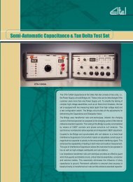
WAVEGUIDE DEHYDRATOR TYPE 12447
to download PDF
to download PDF
- No tags were found...

Create successful ePaper yourself
Turn your PDF publications into a flip-book with our unique Google optimized e-Paper software.
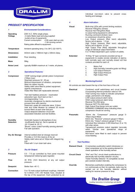
individual non-return valve to prevent crossfeedingand leakage.PRODUCT SPECIFICATION1 Environmental Considerations:OperatingVoltageTemperatureDimensionsInstallationMassNoise Level230V A.C. 50Hz single phase.2 metre Mains lead and plug supplied(outlet at top of equipment).Current consumption: -2.9A upon start-up only-1.0A running current.Rating plate affixed to equipment.Ambient operating temp. 0 to 38°C (32-100°F).443mm wide x 1060mm high x 330mm deep.Floor standing.56kg.typically 60dBA maximum at 1 metre, all planes.2 Operational Features:CompressorAir DrierHumidityDetectionDry Air Storage3 Dry Air Output:PressureFlowDewpointConnection1/3HP rocking single cylinder piston Compressor(100psi max).Stop/start pressure 32 - 65 psi.Minimal transmission of vibration, compressorfitted via rubber mounts.Safety relief valve fitted to protect equipmentagainst overpressure.Intake filter fitted with replaceable element.Twin bed heatless pressure – reactivatedadsorption type. Each bed on line 1min/regenerating 1 min.Automatic changeover by electro-mechanicalprocess timer with memory.Desiccant, grade 4A molecular sieve, 3-5mm.Inlet and outlet filtration by sintered 35 micronbronze filters at each drier bed port.Output dewpoint detection circuit withassociated indication and test facilities.Automatic bypass to atmosphere of anyinsufficiently dried air. Set to operate at-20ºC/reset at -25ºC.“Brown” colour coded humidity sensing element.Fail safe operation.Internal welded steel air storage reservoirProvides a 12.5 litre reserve of dry air.Safety relief valve set at 102psi with integral ringpull.Fitted with ¼ turn drain ball valve.0.5 - 7.0 psi controlled by front panel mountedtamperproof (relieving type) regulator.35 ft³/hr (16.5 litres/min) at any set outputpressure.Better than -40ºC.5 or 10 male output bulkhead couplings, intendedfor 6.35mm (1/4”) OD flexible hose, situated atthe top of the equipment. Each protected by an4 Alarm Indication:VisualExtendedMulti-chip LEDs with current limiting resistors.Receiver Filling/Dry (Green)Receiver Not Filling/Wet (Red)ie output being bypassed to atmosphere.Running command (Amber) neonie compressor should be active.Low Output pressure (Red neon) adjustable,factory set at approx. 1.0 psi.High Output pressure (Red neon) adjustable,factory set at approx. 4.5 psi.High Output Flow (Red) adjustable throughoutrange of individual output flowmeters5 or 10 fitted dependant upon number of outlets.15 Way “D” type connector provided (at top ofequipment) to enable remote indication of alarms;both normally open and normally closed volt freecontacts provided for each of:a. Mains Failb. High Humidity (vessel/w.guide not filling)c. Low Output Pressured. High Output Pressuree. High Output Flow5 Monitoring/Control:All controls are sited toward the top of the front face of the unitElectricalCombined on/off switch/lamp and circuit breakerincorporating thermal protection rated at 10A.Total running hour meter to indicate compressorusage, permanent LCD display.LOW output pressure alarm lamp.HIGH output pressure alarm lamp.Receiver FILLING lamp.Receiver NOT FILLING lamp.High Output Flow lamps (one per outlet).RUNNING COMMAND lamp indicating whencompressor should be running.Pneumatic 63mm dia. “Compressor” pressure gauge 0-150psi (liquid filled).63mm dia. “Receiver” pressure gauge 0-160psi.63mm dia. “Output” pressure gauge 0-15 psi.Individual flow indicators 0-350 litres/hour (5 or 10)with stop valves.Tamperproof precision output regulator (accuratewithin 10mbar over operational range ofequipment).Non-return valve fitted to each output to preventcross-feeding.6 Test Facilities:Element CheckCircuit CheckOverrideA momentary pushbutton switch introduces undriedcompressor air to the sensing element tocheck operation of the humidity sensor.“Wet” and “Dry” circuit check pushbuttons toelectrically test humidity detector circuitry.Tester Humidity Detector 1A compatible via testjack sockets located internally.Momentary pushbutton enabling the compressor torun continuously so that, for example, tests may becarried out on the humidity detector withoutwaiting for receiver pressure to drop.