Industrial
Service and Design Brochure Cover - Drallim Industries
Service and Design Brochure Cover - Drallim Industries

You also want an ePaper? Increase the reach of your titles
YUMPU automatically turns print PDFs into web optimized ePapers that Google loves.
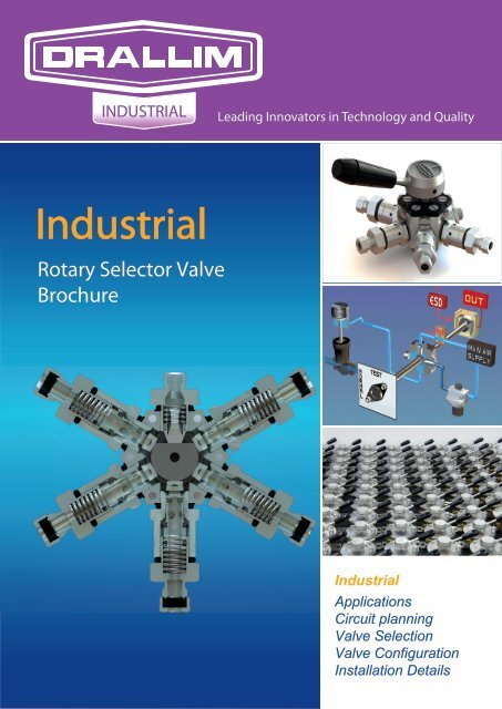
INDUSTRIALLeading Innovators in Technology and Quality<strong>Industrial</strong>Rotary Selector ValveBrochure<strong>Industrial</strong>ApplicationsCircuit planningValve SelectionValve ConfigurationInstallation Details
IntroductionThe late Angus Millard formed Drallim Industries Ltd in 1958: the company name derived byreversing MILLARD to DRALLIM.Angus Millard, a brilliant conceptual engineer designed the Rotary Selector Valve to fulfil the needsof complex switching sequences used in aircraft instrument testing in the process, previously knownas the PIV (Pneumatic Interlok Valve) it is now been re-established as the RSV.RSVs were first made in our factory at Whyteleafe just south of London, then, to allow forexpansion, the company moved to its Bexhill site in 1968. Once again outgrowing its premisesDrallim moved to its current purpose built headquarters in December 2003.Ideally located in the south of England, close to London and its international airports, Heathrow andGatwick, the company now has the added advantage of being just 35 miles from the ChannelTunnel linking the U.K. with mainland Europe.Today Drallim Industries disciplines cover telecommunications, military, electronics and software.The Drallim Controls Division has well established itself as an international supplier of pneumaticbased products, amongst which we are proud to include companies such as Shell and BP to nameonly two of the international giants using our products.Now better known for critical duty products in emergency shutdown valve testing, wellhead control,fire damping, deluge systems, pump control etc, the name Drallim is synonymous with qualityproducts that will enhance the safety of the chemical/petrochemical industries worldwide.- 1 -
The Rotary Selector Valve(Formally called the Pneumatic Interlok Valve)Series 60 RSVA Fluid Control Valve Suitable For Air/Gases/Vapours and other Liquids, Pressure range –1 +10 Bar,Fluid Temperature 85°C (185°F) Available in Brass and St/Stl, with Fluoro-Elastomer Seals and PTFEor ACETAL Resin Stems, depending on the nature of the fluid or gas being used.Some Typical Applications of the RSV: Propeller pitch controls Fuel changeover systems Energy conservation control systems Tank gauging Water fountain display control Cylinder control and bypass and test circuits Emergency stop systems for trainsEmergency Stopsystem on trainsUse within the Process Industry Partial Stroke Testing (Drallim LMT or Limited Movement Testing) Water treatment/polishing plant for nuclear power generation Pneumatic actuator override panels Bypass systems for isolation & diversion of flows Used for flow diversion within pressurised cable systems
Fuel systems: Military Vehicles. Example: Tank Ventilation Systems Aerospace - Ground Test Equipment for Altimeters and Airspeed Indicators Hydraulic Isolation - Low Pressure, High Voltage Cables Gas Analysis Test Sets Purge & Leak Test Set Boats/Submarines NASA - White Sands Test facilityPurge & Leak Test SetBenefits of the RSV over the Multi-Port Ball Valve: Eliminates Cross Port Leakage Each Port Seals Individually Lower Cost Than Multi-Port Ball Valves Electrical Switching Options Caters for very complex configurationsThe Rotary Selector Valve RangeTypical Multi-Port Ball Valve Series 60 Series 40 Series 70 Series 95
Inside The RSVSeries 40 & 70 Valves (fig 1)Product DescriptionEach face of the body (1) is threaded to receive a removable port (2) incorporating also thetubing connector, available in various types and sizes. Valve action is obtained by movement of aspring-loaded stem (3) grooved near its outer end for an o-ring (4) which docks with a conicalseating in the connector body. Movement is caused by rotation of the operating spindle (5) which,being milled with one to three flats, acts as a cam on the stems, opening and closing ports as itturns.In this example, Port 1 (top), being required inoperative, is fitted with a blanking plug (6), whichnevertheless contains a truncated stem and spring to prevent an unbalanced lateral thrust on thespindle. Port 2 (right) has its stem on the full diameter of the spindle and is therefore closed untila flat arrives at that position. Port 3 is required to be permanently open (inlet or outlet) andtherefore has a truncated stem (7) similar to that in Port 1. Port 4 is fully open since its stem is onthe spindle flat, and will also be open in the next clockwise position owing to the adjacent flats.fig 1 fig 2Series 60 Valves (fig 2)Each face of the body (1) is threaded to receive a removable port (2) incorporating also thetubing connector, available in various types and sizes. Valve action is obtained by movement of aspring-loaded stem (3) grooved near its outer end for an o-ring (4) which docks with a conicalseating in the connector body. Movement is caused by rotation of the operating spindle (5) which,being milled with one to five flats, acts as a cam on the stems, opening and closing ports as itturns.IIIIIIIVVVIOperative (in closed position).Operative (in open position).Permanently closed.Operative (in closed position).Permanently open.Venting connector – allows trapped air in line or cylinder to escape to atmosphere throughdrillings (6) in the body as soon as the stem closes onto the supply.As shown, air would be entering Port V (permanently open) and leaving through Port II, the stemof which is on the only flat on this particular spindle. All other ports are closed, temporarily orpermanently(III). Note that when the spindle flat reaches Port V the valve is completely ‘off’. Foralthough this port is open, there is no exit.
Series 40Series 40Ordering ChartWeatherproof Enclosure(for electric switch only)YesWNo No code requiredElectric Switch CodeSee Electric Switch PageNo. of Positions2,3,4(No code required if unrestricted)MountingPanel (No code required)Base Mounting Plate 1Positive PositioningPositive Positioning comes froman indexing mechanism allowingthe operator to have genuine feelof the valves various positions,eliminating the possibility of thevalve being left in mid position.FlexibilityFlexibility comes from the factthat each valve can have its ownunique inner spindle, so withmultibank valves each bank canhave its own configuration.SecurityShould it be required, security isprovided by keylocking the valve.Heavy-duty stainless steelversions are available for harshenvironments.Electrical InterfaceElectrical Interface is providedfrom a rotary electrical switchdirectly coupled to the spindleand mounted on the base of thevalve.Connections1/4“ BSP Female F21/4“ NPT Female F6OperatorsKnobLeverKey Lock T TypePort CodeNo. of BanksClass (See Below)Class B:Brass BodyStainless Steel SpindleAcetal Resin StemsFluoro Elastomer SealsClass C:Brass BodyStainless Steel SpindlePTFE StemsFluoro Elastomer SealsClass D:Stainless Steel BodyStainless Steel SpindleAcetal Resin StemsFluoro Elastomer SealsClass E:Stainless Steel BodyStainless Steel SpindlePTFE StemsFluoro Elastomer SealsADF1 to 8EXAMPLE B 1 02 A F6 1Please note that venting connectors cannot be fitted to valves in class C and E
Series 40 Port CodingWith a choice of operative, permanently open and permanently closed ports in any of the fourpositions, plus a spindle with one flat, two adjacent, two opposite, or three flats, the number ofpermutations in just one bank is clearly enormous.In practice however the great majority of requirements are to be found from amongst the 32 bank configurationsshown and coded below.These show not only a cross-section through the banks in a highly simplified form but, alongside, a representationof how the flow paths change as the knob is turned.Permanently open and permanently closed ports are quite obvious, the way of showing the permanently-open baseconnection first appears in Code 04, and the venting connector in Code 20. Although the banks are sealedinternally from one another, there is nothing to prevent an external connection between any two banks by tubing.In ordering multibank valves the bank nearest the handle is coded first, and banks calling for a base connectioncan be used only in the last or lowermost position. A base-mounted electrical rotary switch precludes this option.Banks can be assembled together in any orientation required, but unless requested multibank RSVs will besupplied with all banks orientated as shown below.SERIES 40 PORT CODINGS1101 0210310422224444333310510610710822224444333310911011111222224444333311311411 5116222444433331171181191202222444433331211221231242222444433331251261271282222444433 33129130131132222244443333
Series 40 InstallationPanelMountingDetailHandle OptionsBody DimensionsNo Of BanksDimension X1 462 763 1064 1365 1666 196All Dimensions In mmBase Mounting DetailSmart ValveMonitoringIEC 61508
Notes
Series 60Series 60Ordering ChartWeatherproof Enclosure(for electric switch only)YesWNo No code requiredElectric Switch CodeSee Electric Switch PageNo. of Positions2,3,4,5,6(No code required if unrestricted)Proven DesignSeries 60 Valves encompass thesame proven design of the Series40 Valve but offer far greaterpermutations.VersatilityWith the choice of operative,permanently open andpermanently closed ports in anyof the six positions, plus a spindlewith 1 to 5 flats the number ofpermutations in just one bank isclearly enormous.ApplicationsSeries 60 Valves cover manyapplications including multi-tankgauging systems, compressorunloader systems and all wheeldrive selection on militaryvehicles.Environmental DetailsFluids Air and other gases,vapours and liquids compatiblewith the materials of construction.Pressure RangeFluid Temperature-1 to +10 bar85°C (185°F)MountingPanel mounting only(No code required)Connections1/4“ BSP Female F21/4“ NPT Female F6OperatorsKnobLeverPort CodeNo. of BanksClass (See Below)Class V:Brass BodyStainless Steel SpindleAcetal Resin StemsFluoro Elastomer SealsClass W:Brass BodyStainless Steel SpindlePTFE StemsFluoro Elastomer SealsClass X:Stainless Steel BodyStainless Steel SpindleAcetal Resin StemsFluoro Elastomer SealsClass Y:Stainless Steel BodyStainless Steel SpindlePTFE StemsFluoro Elastomer SealsEXAMPLEAD1 to 6Smart ValveMonitoringV 1 50 C F2IEC 61508Please note that venting connectors cannot be fitted to valves in class W and Y
Series 60 Port CodingWith a choice of operative, permanently open and permanently closed ports in any of the sixpositions, plus a spindle with from 1 to 5 flats the number of permutations in just one bank isclearly enormous.In practice however the great majority of requirements are to be found from amongst the 21 bankconfigurations shown and coded below.These show not only a cross-section through the banks in a highly simplified form but, alongside,a representation of how the flow paths change as the knob is turned.Permanently open and permanently closed ports are quite obvious, the way of showing thepermanently-open base connection first appears in Code 51, and the venting connector in Code63. Although the banks are sealed internally from one another, there is nothing to prevent anexternal connection between any two banks by tubing.In ordering multibank valves the bank nearest the handle is coded first, and banks calling for abase connection can be used only in the last or lowermost position. A base-mounted electricalrotary switch precludes this option. Banks can be assembled together in any orientation required,but unless requested multibank PIVs will be supplied with all banks orientated as shown below.SERIES 60 PORT CODINGS125015121252666333555444125312541552666333555444156212571258666333555444159 601221261666333555444126212631642666333545454165212661672666333545454168216921270666333545454121212121212666666333333555555444444
Series 60 InstallationPanelMountingDetailHandle OptionsBody DimensionsNo Of Banks Dim X Dim Y1 32 42.52 60 753 85.5 964 113.5 128.55 139 1506 167 182Connector TypeDim ZBlanking Plug 28Venting 60O/D Tube 39.5Female Threaded 41All Dimensions In mmBase Mounting Detail
Notes
Series 70Series 70Ordering ChartWeatherproof Enclosure(for electric switch only)YesWNo No code requiredElectric Switch CodeSee Electric Switch PageNo. of Positions2,3,4(No code required if unrestricted)MountingPanel (No code required)Base Mounting Plate 1High Flow CapacitySeries 70 Valves offer a higherflow capacity than their sisterproducts, 40 & 60 Series.FlexibilityFlexibility is once more a majorfeature of our product design.Many spindle combinations andvalve arrangements can beaccommodated including baseentry types.VersatilityUsed in a wide variety ofapplications this robust product isparticularly useful in emergencyshut down applications where thevalve is used as a kill switch onisolated offshore platforms.PermutationsWith the choice of operative,permanently open andpermanently closed ports in anyof the four positions, plus aspindle with one flat, twoadjacent, two opposite, or threeflats, the number of permutationsin just one bank is clearlyenormous.Connections3/8“ NPT Female F71/2“ NPT Female F8 SS onlyOperatorsLeverKey Lock T TypePort CodeDFNo. of Banks(2 Banks Maximum) 1 or 2Class (See Below)Class P:Brass BodyStainless Steel SpindleAcetal Resin StemsFluoro Elastomer SealsClass R:Brass BodyStainless Steel SpindlePTFE StemsFluoro Elastomer SealsClass S:Stainless Steel BodyStainless Steel SpindleAcetal Resin StemsFluoro Elastomer SealsClass T:Stainless Steel BodyStainless Steel SpindlePTFE StemsFluoro Elastomer SealsEXAMPLE T 1 02 D F8 1
Series 70 Port CodingWith a choice of operative, permanently open and permanently closed ports in any of the fourpositions, plus a spindle with one flat, two adjacent, two opposite, or three flats, the number ofpermutations in just one bank is clearly enormous.In practice however the great majority of requirements are to be found from amongst the 26 bankconfigurations shown and coded below.These show not only a cross-section through the banks in a highly simplified form but, alongside,a representation of how the flow paths change as the knob is turned.Permanently open and permanently closed ports are quite obvious, the way of showing thepermanently-open base connection first appears in Code 04. Although the banks are sealedinternally from one another, there is nothing to prevent an external connection between any twobanks by tubing.In ordering multibank valves the bank nearest the handle is coded first, and banks calling for abase connection can be used only in the last or lowermost position. A base-mounted electricalrotary switch precludes this option. Banks can be assembled together in any orientation required,but unless requested multibank RSVs will be supplied with all banks orientated as shown below.SERIES 70 PORT CODINGS10110210310422224444333310510610710822224444333310911011111222224444333311311411511622224444333311711811912322224444333312412512612722224444333128130224433
CSeries 70 InstallationPanelMountingDetailHandle OptionsBody DimensionsNo Of BanksDimension X1 39.52 79All Dimensions In mmBase Mounting DetailC50.066.6
Notes
Series 95Series 95Ordering ChartWeatherproof Enclosure(for electric switch only)YesWNo No code requiredElectric Switch CodeSee Electric Switch PageNo. of Positions2,3,4(No code required if unrestricted)MountingPanel (No code required)Base Mounting Plate 1Connections1/2“ NPT Female F81/2“ Spigot S83/8” Spigot S7OperatorsLeverKey Lever TypePort CodeHigh Flow CapacitySeries 95 Valves offer a higherflow capacity than their sisterproducts, 40 & 60 Series.VersatilityUsed in a wide variety ofapplications this robust product isparticularly useful in emergencyshut down applications.PermutationsWith the choice of operative,permanently open andpermanently closed ports in anyof the four positions, plus aspindle with one flat, twoadjacent, two opposite, or threeflats, the number of permutationsin just one bank is clearlyenormous.No. of BanksClass (See Below)Class P:Brass BodyStainless Steel SpindleAcetal Resin StemsFluoro Elastomer SealsClass R:Brass BodyStainless Steel SpindlePTFE StemsFluoro Elastomer SealsClass S:Stainless Steel BodyStainless Steel SpindleAcetal Resin StemsFluoro Elastomer SealsClass T:Stainless Steel BodyStainless Steel SpindlePTFE StemsFluoro Elastomer Seals1 to 4EXAMPLE 95 P 1 02 L F8 1
Electric SwitchesThe combination of a multipole electric switch with the Drallim valves heralds a new era inprocess safety systems.The introduction of an explosion category electric switch further enhances the applications towhich these devices are applied.Typical applications are feedback to DCS systems, remote and local actuation of fire preventionand damping systems, graduated loading and unloading of compressors, starting and stoppingpumping systems.The electric switches below can be fitted to the valves detailed within this catalogue withexception of those with a base entry connection.4 & 6 Way EEx d IIB T4-T6 IP67 Single PoleSPECIFICATIONSExplosion Protection Code EEx d IIB T4-T6Electrical Ratings15A/250 VAC10A/28 VDC0.2A/125 VDCSwitchV3 SPDTGland Entry (2 off) M20 X 1.5Ingress ProtectionIP67Enclosure MaterialAluminiumOrder CodeWL4 & 6 Way Non EEx d Multi PoleSPECIFICATIONSVoltage (nominal)Current (rated)Weatherproof Enclosure (optional)690v20AIP654 WayNo. of Poles 1 2 3 4 5 6No. of Stages 1 2 3 4 5 6Order Code 2843 2844 2845 2846 2847 28486 WayNo. of Poles 1 2 3 4No. of Stages 2 3 5 6Order Code 2853 2854 2855 2856