Gravity-loaded axes
Gravity-loaded axes
Gravity-loaded axes

You also want an ePaper? Increase the reach of your titles
YUMPU automatically turns print PDFs into web optimized ePapers that Google loves.
__<br />
__<br />
__<br />
No. 005<br />
Edition 09/2012 Division Information Sheet<br />
<strong>Gravity</strong>-<strong>loaded</strong> <strong>axes</strong><br />
Vertical <strong>axes</strong><br />
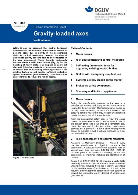
While it can be assumed that during horizontal<br />
movements in the automatic production no hazards to<br />
persons occur due to gravity in the de-energized<br />
state, for vertical movements, however, the risks of<br />
unintended gravity descent have to be considered in<br />
the risk assessment. These hazards particularly<br />
become obvious with linear robots (Fig. 1) for the<br />
handling of heavy parts, e. g. engines or gears but<br />
also with jointed-arm robots or inside machines, e.g.<br />
at vertical <strong>axes</strong> of machining or turning centers. If the<br />
existing brakes do not provide sufficient protection<br />
against unintended gravity descent, control measures<br />
can contribute to reduce the risk of hazard.<br />
Figure 1: Vertical <strong>axes</strong><br />
Table of Contents<br />
1 Motor brakes<br />
2 Risk assessment and control measures<br />
3 Self-acting (automatic) tests for<br />
upgrading existing (motor) brakes<br />
4 Brakes with emergency stop features<br />
5 Systems already placed on the market<br />
6 Brakes as safety component<br />
7 Summary and limits of application<br />
1 Motor brakes<br />
During the manufacturing process, vertical <strong>axes</strong> at a<br />
standstill are usually held solely by the brake which is<br />
installed in the drive motor. Mechanical wear or fouling by<br />
oil may cause the braking moment of the brakes to fall<br />
below its nominal value which may result in an unintended<br />
gravity descent or the fall down of the axis.<br />
From the occupational safety point of view, the cases<br />
have to be considered in which persons have access to<br />
the danger zones and a full-time or a temporary stay<br />
under the axis, e.g. for feeding, setting, maintenance<br />
activities etc. is possible. If a failure of the holding brakes<br />
cannot be excluded in such situations, measures for a risk<br />
reduction shall be taken.<br />
2 Risik assessment and control measures<br />
According to Machinery Directive [1] Annex I, every<br />
machine manufacturer is obliged to prepare a risk<br />
assessment. A particular standard for assessing risks at<br />
vertical <strong>axes</strong> does not exist. DIN EN ISO 12100 [2]<br />
provides general information for carrying out the risk<br />
assessment at machines including the identification of<br />
hazards.<br />
Annex B of DIN EN ISO 12100 provides a useful table<br />
indicating possible hazards which have to be considered<br />
with machines, including those due to gravity. Depending<br />
on the practical case of application and the risk to be<br />
reduced, different technical safety devices are suitable to<br />
prevent the unintended gravity descent of vertical <strong>axes</strong><br />
(see table 3).
Division information sheet No. 005 Edition 09/2012 Page 2 / 7<br />
<strong>Gravity</strong>-<strong>loaded</strong> <strong>axes</strong> - vertical <strong>axes</strong><br />
The examples indicated in table 1 are intended to be a<br />
guidance for the risk assessment for such systems. By<br />
presenting typical hazardous situations, adequate<br />
technical and organizational measures are proposed in<br />
order to prevent unintended gravity descent. Besides the<br />
measures shown in table 1, there exist of course the<br />
relevant EC directives and standards specifying further<br />
requirements for occupational safety for the machinery in<br />
question, the validity of which remains unaffected.<br />
3 Self-acting (automatic) tests for<br />
upgrading existing (motor) brakes<br />
According to the principles of the risk analysis, the<br />
summary in Table 1 considers the duration of stay, the<br />
severity of the possible injury and the probability of the<br />
occurrence of a hazardous situation. Therefore, redundant<br />
measures according to DIN EN ISO 13849-1 category 3<br />
are proposed for highly exposed workplaces, which<br />
require a high duration of stay or frequent access [3].<br />
Further explanations for implementing the measures<br />
according to category 3 are given in table 2.<br />
For other activities in case of which e.g. a protective<br />
design prevents the access underneath the vertical axis or<br />
the probability of the occurrence of a hazardous situation<br />
and the duration of stay is less, a cyclic test of the single<br />
motor brake (brake test) can be a very effective measure.<br />
For this, a test moment is applied to the brake, e.g. motor<br />
brake. This test should be carried out according to the<br />
requirements of DIN EN ISO 13849-1, category 2 (see<br />
table 2). I.e. the test shall take place automatically during<br />
normal production, e.g. during a process-related stop, in<br />
case of a change of the mode of operation or similar. If<br />
this is not possible, the test shall be carried out prior to<br />
releasing access by a guard with guard locking at the<br />
latest.<br />
Note:<br />
According to DIN EN ISO 13849-1, the test rate for control<br />
systems of category 2 (checking) has to be estimated a<br />
100 times more frequent than the demand upon the safety<br />
function. Due to the risks of vertical <strong>axes</strong>, i.e. particularly<br />
due to the accident history, such a high test rate is<br />
considered to be actually not required. Therefore, a<br />
calculation of the Performance Level according to the<br />
simplified procedures of DIN EN ISO 13849-1 is not<br />
possible and can be omitted in this particular case<br />
according to DIN EN ISO 13849-1, clause 6.2.2.<br />
4 Brakes with emergency stop features<br />
If the brakes should not only safely maintain the load in a<br />
raised position but should also be provided with<br />
emergency stop features (e. g. in case of protective stop<br />
actuation), it should be pointed out that the self-acting<br />
static brake tests do not provide sufficient proof with<br />
regard to inadequate or decreasing emergency stop<br />
features. This means that despite a successfully<br />
performed static brake test, a slightly extended overrun in<br />
case of emergency stop is possible since the physical<br />
characteristics of the brake have different dynamic and<br />
static effects. The risk assessment of the machine<br />
manufacturer must indicate in such cases if a slightly<br />
different overrun in the course of the operating life<br />
represents an inacceptable risk.<br />
Note:<br />
In order to refrain from providing emergency stop features<br />
to the brakes, a category 1 stop (guided stopping) should<br />
be preferred in case of a protective stop.<br />
5 Systems already placed on the market<br />
The above mentioned measures for the improvement of<br />
occupational safety at vertical <strong>axes</strong> are primarily suitable<br />
for application at systems which are intended to be put on<br />
to the market.<br />
Machinery and systems (used systems) that are already<br />
on the market shall meet the requirements of the<br />
Betriebssicherheitsverordnung (Ordinance on Industrial<br />
Safety and Health) [4] and the accident prevention<br />
regulations of the institutions for statutory accident<br />
insurance and prevention (Unfallverhütungsvorschriften<br />
der Berufsgenossenschaften).<br />
The technical safety measures which have to be specified<br />
correspondingly must not necessarily reach the same<br />
level as those specified for new machinery according to<br />
the Machinery Directive. The decisive factor is the state of<br />
the art at the time when the machine is put on the market<br />
for the first time and the development of the state of the<br />
art by the accident prevention regulations.<br />
In particular, safety measures for risk reduction by control<br />
have mainly been established owing to recent findings.<br />
Measures by control cannot be easily retrofitted with the<br />
existing hard- and software. The employer is required to<br />
take measures according to § 4 of the BetrSichV<br />
(Ordinance on Industrial Safety and Health) in order to<br />
keep the hazard as low as possible. If the risks cannot be<br />
adequately reduced by technical safety measures,<br />
organizational measures have to be taken which<br />
contribute to the risk reduction (avoidance of presence<br />
underneath the axis, support etc.). Furthermore,<br />
employees have to be enabled by relevant instructions to<br />
assess hazards adequately. An essential element in this<br />
connection should also be the provision of periodic tests<br />
for detecting hazardous wear conditions. The kind, the<br />
scope, the test periods and the skill level of the testing<br />
personnel have to be specified by the user. The skilled<br />
person shall have sufficient knowledge and experience in<br />
the field of the work equipment to be tested and must be<br />
familiar with the relevant national occupational health and<br />
safety regulations, BG-rules and generally accepted rules<br />
of technique (e.g. regulations determined by the<br />
committee for rules for Operational Reliability, DIN<br />
standards, VDE regulations, technical regulations of other<br />
member countries of the European Union or other<br />
contracting states of the agreement about the European<br />
Economic Area) so that he is able to assess the safe state<br />
of the work equipment.<br />
6 Brakes as safety component<br />
Brakes for holding up vertical <strong>axes</strong> can be classified as<br />
safety component according to the Machinery Directive<br />
2006/42/EC, article 2 no. c). The precondition is that the<br />
brakes are put on the market separately, i.e. independent<br />
of the machine or the drive motor. In this case, the<br />
conformity assessment procedures which apply to<br />
machines have to be used, amongst others, EC<br />
Declaration of conformity and EC mark.<br />
These provisions do not apply to motor brakes since they<br />
are not separately put on the market due to the fact that<br />
they are built into the drive motor.<br />
In this connection it should be pointed out to the fact that<br />
by means of tests and certifications according to test<br />
principle no. GS-MF-28 the proof of an operation-proven<br />
brake (category 1, Plc) can be certified [5].
Division information sheet No. 005 Edition 09/2012 Page 3 / 7<br />
<strong>Gravity</strong>-<strong>loaded</strong> <strong>axes</strong> - vertical <strong>axes</strong><br />
7 Summary and limits of application<br />
The measures mentioned in this division information sheet<br />
for occupational safety represent the results of detailed<br />
discussions in the woodworking and metalworking division<br />
(Fachbereich Holz und Metall) concerning an improved<br />
occupational safety for activities at or near vertical <strong>axes</strong>.<br />
They include practical technical control measures against<br />
unintended descent due to gravity. This information sheet<br />
is based on experience of manufacturers of industrial<br />
robots including linear robots and handling systems, of<br />
drive and control system manufacturers and the users of<br />
such systems, particularly in the automotive engineering<br />
and on experience of the woodworking and metalworking<br />
division. Furthermore, the results of the discussions have<br />
been considered at the Association of German Machine<br />
Tool Manufacturers (VDW).<br />
This information sheet indicates typical hazardous<br />
situations in connection with vertical <strong>axes</strong> and provides<br />
suitable approaches for risk reduction by technical control<br />
measures. Other measures against unintended gravity<br />
descent which are not mentioned in this information sheet<br />
remain unaffected.<br />
Subject of consideration are electro-motive driven vertical<br />
<strong>axes</strong> as well as inclined <strong>axes</strong> with motor-integrated brake<br />
or external brake which could descent in case of failure<br />
due to gravity. Relevant requirements stated in EC<br />
Directives and other rules of Technique remain<br />
unaffected. The developments of new technologies as<br />
well as equivalent solutions are not impeded by this<br />
information sheet. The applicability of the findings to<br />
machinery and systems with similar hazards is not<br />
excluded.<br />
The measures may preferably be applied for systems<br />
which are put onto the market for the first time.<br />
Particularities at systems which are already placed on the<br />
market will be dealt with separately. The contents of this<br />
information sheet are intended to be included in the<br />
technical rules or have already been included.<br />
The “Fachbereich Holz und Metall” (Woodworking and<br />
metalworking division) is composed of representatives of<br />
the German Social Accident Insurance Institution, federal<br />
authorities, social partners, manufacturers and users of<br />
machines. It is based on experience gathered by the FB<br />
Holz und Metall in the field of vertical <strong>axes</strong> and in<br />
particular in the field of gravity-<strong>loaded</strong> <strong>axes</strong>.<br />
This division information sheet has been prepared by the<br />
metalworking and woodworking division, subdivision<br />
“machinery, systems, automation and design of<br />
manufacturing systems”. This division information sheet<br />
replaces information sheet, draft 07/2011. Further<br />
information sheets published by the woodworking and<br />
metalworking division may be down<strong>loaded</strong> from the<br />
Internet [6].<br />
Concerning the aims of the division information sheets,<br />
see division information sheet no. 001.<br />
Bibliography:<br />
[1] Directive 2006/42/EC (Machinery directive) of the European<br />
Parliament, L157, 2006-06-09.<br />
[2] DIN EN ISO 12100 Safety of machinery - General principles for<br />
design - risk assessment and risk reduction March 2011.<br />
[3] DIN EN 13849-1 Safety of machinery - Safety-related parts of control<br />
systems - Part 1 - General principles for design, December 2008.<br />
[4] Verordnung über Sicherheit und Gesundheitsschutz bei der<br />
Bereitstellung von Arbeitsmitteln und deren Benutzung bei der Arbeit,<br />
über die Sicherheit beim Betrieb überwachungsbedürftiger Anlagen<br />
und über die Organisation des betrieblichen Arbeitschutzes<br />
(Betriebssicherheitsverordnung – BetrSichV). BGBl. I S. 3777 - 27.<br />
September 2002. edition 2004<br />
[5] Prüfgrundsatz Nr. GS-MF-28 Notfallbremsen mit Haltebremsfunktion<br />
für lineare Bewegungen. Prüf- und Zertifizierungsstelle Maschinen<br />
und Fertigungsautomation im DGUV Test, Wilhelm-Theodor-Römheld-<br />
Strasse 15, 55130 Mainz. (Inhaltlich gleichlautend vorhanden bei IFA).<br />
[6] Internet: www.dguv.de/fb-holzundmetall Publikationen<br />
Picture credits:<br />
The pictures mentioned in this division information sheet have been kindly<br />
provided by: FB Holz und Metall<br />
Publisher:<br />
Fachbereich Holz und Metall der DGUV<br />
Sachgebiet Maschinen, Anlagen, Fertigungsautomation und -gestaltung<br />
Postfach 37 80<br />
55027 Mainz<br />
Woodworking and Metalworking Division of DGUV<br />
Subdivision machinery, plants, automation and design of manufacturing<br />
systems
Division information sheet No. 005 Edition 09/2012 Page 4 / 7<br />
<strong>Gravity</strong>-<strong>loaded</strong> <strong>axes</strong> - vertical <strong>axes</strong><br />
Table 1: Typical hazardous situations and possible protective measures<br />
Mode of<br />
operation<br />
Automatic-<br />
Manual<br />
intervention<br />
A1<br />
A2<br />
A3<br />
Set-up or<br />
programming<br />
E1<br />
Hazardous situation/ Safety measures<br />
Intended use Technical Organizational<br />
During manual intervention, the<br />
vertical axis is located in a safe<br />
position for the operator (accessprotected<br />
area).<br />
The vertical axis is located within<br />
the hazardous area.<br />
Staying under the vertical axis with<br />
the whole body is prevented by the<br />
machine / system design and not<br />
intended. A hazard exists for the<br />
upper limbs in case of a short<br />
duration of stay.<br />
The vertical axis is located within<br />
the hazardous area.<br />
Staying under the vertical axis<br />
cannot be prevented (e.g. intended<br />
feeding or assembling activities).<br />
- Guards have to be provided with guard lockings.<br />
- In case of access, unintended start of the vertical axis shall<br />
be safely prevented.<br />
- Cyclic test of the braking device by the machine control<br />
according to DIN EN ISO 13849-1, category 2 (see table<br />
2).<br />
- Unexpected start of the vertical axis shall be safely<br />
prevented 1). .<br />
- Redundant device for fall-down protection according to DIN<br />
EN ISO 13849-1, category 3, PLc (see table 2).<br />
- Unexpected start of the vertical axis shall be safely<br />
prevented 1).<br />
- Warning sign mounted at the machine / system: „ Do not<br />
stay underneath the vertical axis!“<br />
- Point out to hazards due to vertical axis and suspended load<br />
in the operating instructions.<br />
- Warning sign mounted at the machine / system: „ Do not<br />
stay underneath the vertical axis!“<br />
- Point out to hazards due to vertical axis and suspended load<br />
in the operating instructions as well as to the need for skilled<br />
personnel.<br />
- Commissioning test to be carried out by the system<br />
manufacturer by means of a form with regard to the<br />
effectiveness of the brake test.<br />
- Warning sign mounted at the machine / system: „ Do not<br />
stay underneath the vertical axis!“<br />
- Point out to hazards due to vertical axis and suspended load<br />
in the operating instructions as well as to the need for skilled<br />
personnel.<br />
Limit stay under the vertical axis as far as possible.<br />
The vertical axis is located in a safe<br />
position for the operator during setup<br />
(access-protected area).<br />
- Guards have to be provided with guard lockings<br />
- In case of access, unintended start of the vertical axis shall<br />
be safely prevented).<br />
- Warning sign mounted at the machine / system:<br />
„ Do not stay underneath the vertical axis!“<br />
- Point out to hazards due to vertical axis and suspended load<br />
in the operating instructions.
Division information sheet No. 005 Edition 09/2012 Page 5 / 7<br />
<strong>Gravity</strong>-<strong>loaded</strong> <strong>axes</strong> - vertical <strong>axes</strong><br />
Table 1 (continued)<br />
Mode of<br />
operation<br />
E2<br />
E3<br />
Maintenance,<br />
repair,<br />
cleaning<br />
W1<br />
W2<br />
Hazardous situation/ Safety measures<br />
Intended use Technical Organizational<br />
The vertical axis is operated in the<br />
set-up mode and is located within<br />
the hazardous area. Staying under<br />
the vertical axis with the whole body<br />
is prevented by the machine /<br />
system design and not intended. A<br />
hazard exists for the upper limbs for<br />
a short duration of stay.<br />
The vertical axis is operated in the<br />
set-up mode and is located within<br />
the hazardous area. Staying under<br />
the vertical axis with the whole body<br />
cannot be prevented, however<br />
during a short duration of stay.<br />
Maintenance, cleaning and repair<br />
works are carried out at or next to<br />
the vertical axis.<br />
Safe support of the vertical axis and<br />
/ or suspension with reasonable<br />
effort is feasible.<br />
Maintenance, cleaning and repair<br />
works are carried out at or next to<br />
the vertical axis.<br />
Safe support and / or suspension of<br />
the vertical axis is not feasible with<br />
reasonable effort.<br />
- Measures for set-up operation according to relevant standard,<br />
e.g. DIN EN ISO 10218-1, DIN EN 12417 (lockable mode<br />
selection switch, reduced speed + enabling device/ safely<br />
reduced speed …)<br />
- Cyclic test of braking device by the machine control system<br />
according to DIN EN ISO 13849-1, category 2 (see table 2).<br />
- Measures for set-up operation according to relevant standard,<br />
e.g. EN ISO 10218-1, DIN EN 12417 (lockable mode selection<br />
switch, reduced speed + enabling device/ safely reduced<br />
speed …)<br />
- Cyclic test of braking device by the machine control system<br />
according to DIN EN ISO 13849-1, category 2 (see table 2).<br />
- If, in exceptional cases a high duration of stay can be expected<br />
in the hazardous area, and if staying under the vertical axis<br />
cannot be avoided, measures according to DIN EN ISO<br />
13849-1, category 3 have to be provided (see table 2).<br />
- Observe the regulations in force for maintenance/ repair/<br />
cleaning, e.g. lockable mains switch.<br />
- Support or, as far as still possible, move to lowest end position<br />
- Observe the regulations in force for maintenance/<br />
repair/cleaning, e.g. lockable mains switch.<br />
- Device to be operated automatically or electromechanically<br />
resp. manually for safe arresting of the axis in the defined<br />
positions, e.g. arresting device.<br />
- Clear marking of the positions „interlocked/unlocked“.<br />
- Interrogation of positions by the control „interlocked/ unlocked“<br />
and interlocking with drive control.<br />
- Warning sign mounted at the machine / system: „ Do not<br />
stay underneath the vertical axis!“<br />
- Point out to hazards due to vertical axis and suspended<br />
load in the operating instructions as well as to the need for<br />
skilled personnel.<br />
- Commissioning test to be carried out by the system<br />
manufacturer by means of a form with regard to the<br />
effectiveness of the brake test.<br />
- Warning sign mounted at the machine / system: „ Do not<br />
stay underneath the vertical axis!“<br />
- Point out to hazards due to vertical axis and suspended<br />
load in the operating instructions as well as to the need for<br />
skilled personnel.<br />
- Commissioning test to be carried out by the system<br />
manufacturer by means of a form with regard to the<br />
effectiveness of the brake test.<br />
- Warning sign mounted at the machine / system: „Do not<br />
stay underneath the vertical axis!“<br />
- Point out to hazards due to vertical axis and suspended<br />
load in the operating instructions<br />
- Describe measures for safe support<br />
- Disconnect and lock mains switch<br />
- Warning sign mounted at the machine / system: „Do not<br />
stay underneath the vertical axis!“<br />
- Point out to hazards due to vertical axis and suspended<br />
load in the operating instructions<br />
- Describe measures for the use of the devices for safe<br />
arresting (e.g. arresting device)<br />
- Disconnect and lock mains switch<br />
1) Note: The control category and the Performance Level (PL) with regard to protection against unexpected start-up can usually be taken from the applicable product standards. In<br />
most cases, category 3, PLd applies.
Division information sheet No. 005 Edition 09/2012 Page 6 / 7<br />
<strong>Gravity</strong>-<strong>loaded</strong> <strong>axes</strong> - vertical <strong>axes</strong><br />
Table 2: Examples of measures against unintended descent of gravity-<strong>loaded</strong> <strong>axes</strong> (vertical <strong>axes</strong>) according to DIN EN ISO 13849-1 category 2 and 3.<br />
1 General requirements<br />
1.1 The mechanical parts of power transmission and the safety devices shall be at least designed to withstand the occurring static and dynamic stresses at double weight load.<br />
1.2 If a brake fault is detected by control means according to DIN EN ISO 13849-1, category 2 or 3, the vertical axis shall immediately approach a safe position in case of protective devices or unlocked protective<br />
doors, as far as this is still possible. The indications given by the machine control shall request for brake repair. In case of guards with locked protective doors, a safe position shall not be approached until an<br />
unlock demand signal has been given.<br />
1.3 One or several warning signs shall be visibly fixed at the machine pointing out to hazards due to vertical <strong>axes</strong> and suspended loads.<br />
1.4 The operating instructions shall describe measures for fall-down protection. They shall point out to hazards due to vertical <strong>axes</strong> and suspended loads.<br />
1.5 Measures against unauthorised access to safety relevant programme parts of the control system shall be provided, e.g. by one of the following measures:<br />
- write protection for relevant parts of the programme<br />
- password protection<br />
- modification protection by means of a key switch<br />
1.6 In order to prevent unnecessary wear of the brakes, preference should be given to stop category 1 (controlled stopping) - if permitted by the risk assessment - according to EN 60204-1, for operational stop and<br />
for emergency stop, instead of stopping with mechanical brakes.<br />
2 Measures according to DIN EN ISO 13849-1, category 2 (cyclic brake test)<br />
2.1 The brake test shall be carried out in a safe position for the operator, e.g. safe parking position, closed guard.<br />
2.2 The brake test shall become effective automatically during normal operation of the vertical axis, however, after 8 hours or a shift at the latest. For systems to which access is safely prevented, ( e.g. by means of<br />
protective doors with guard locking), the test may be effected immediately prior to access after unlock demand signal.<br />
Note: According to DIN EN ISO 13849-1, the test rate for control systems of category 2 (checking) has to be estimated a 100 times more frequent than the demand upon the safety function. Due to the risks of<br />
vertical <strong>axes</strong>, i.e. particularly due to the accident history, such a high test rate is considered to be actually not required. Therefore, a calculation of the Performance Level according to the simplified<br />
procedures of DIN EN ISO 13849-1 is not possible and can be omitted in this particular case according to DIN EN ISO 13849-1, clause 6.2.2.<br />
2.3 By the brake test it shall be established, that at least the maximum static weight of the load of the axis occurring in the case of application is held safely. The level of the test moment has to be selected<br />
accordingly, i.e. 1,3-times the load torque. If several brakes are applied in a parallel manner, (e.g. two brakes) this is considered to be fulfilled if the braking devices are tested separately one after the other on the<br />
simple weight load.<br />
2.4 In order to ensure its total effectiveness, the test moment shall be applied over a sufficient time period.<br />
2.5 After repair of a defective brake, a brake test shall be forced by the control system and completed successfully prior to further operation.<br />
2.6 As to the effectiveness of the brake test, an acceptance test at the commissioning of the machine shall be carried out and recorded. During this acceptance test, a failure condition of the brake device shall be<br />
simulated and the corresponding fault reaction shall be checked. For this acceptance test, the machinery manufacturer shall provide a form and prescribe the need for skilled personnel. The acceptance test shall<br />
be carried out with a reasonable effort.<br />
3 Measures according to DIN EN ISO 13849-1, category 3 (redundant measures for fall-down protection):<br />
3.1 Devices for holding the vertical axis shall be of redundant design (see also table 3: Assignment of common braking devices to the individual modes of operation). If devices are applied which are not considered in<br />
table 3, they have to be classified logically according to table 1.<br />
3.2 Measures for partial fault detection according to DIN EN ISO 13849-1 category 3 PLc shall be provided. Those measures include:<br />
3.2.1 For electronic signal processing units: compilation of measures for detecting and controlling systematic and random faults.<br />
3.2.2 Evaluation of signal states of sensors and actuators and signal processing units. Fault conditions shall result in a fail safe reaction<br />
3.2.3 If a continuous state monitoring of parts of the control system is not feasible, forced dynamizations shall be provided. E.G.: since motor brakes in general do not dispose of reliable signal outputs with regard to the<br />
brake state „open/closed“, a forced dynamization according to 2 (cyclic brake test) may be provided as measure for fault detection for the motor brake, for the case that one channel of the dual channel holding<br />
system with motor brake is implemented.
Division information sheet No. 005 Edition 09/2012 Page 7 / 7<br />
<strong>Gravity</strong>-<strong>loaded</strong> <strong>axes</strong> - vertical <strong>axes</strong><br />
Table 3: Assignment of common braking devices to the individual modes of operation<br />
Design of braking device(s) Suitable for<br />
mode of<br />
operation<br />
A1<br />
Suitable for<br />
mode of<br />
operation<br />
A2<br />
During manual intervention, the<br />
vertical axis is located in a safe<br />
position for the operator within the<br />
hazardous area (in waiting position)<br />
or in an access-protected area.<br />
The vertical axis is located within<br />
the hazardous area. Staying under<br />
the vertical axis is prevented by the<br />
machine / system design. A hazard<br />
exists for the upper limbs.<br />
Suitable for<br />
mode of<br />
operation<br />
A3<br />
The vertical axis is located within<br />
the hazardous area. Staying under<br />
the vertical axis cannot be avoided.<br />
Suitable for mode of<br />
operation<br />
E1<br />
The vertical axis is not operated in<br />
the set-up mode and is located<br />
during manual intervention in a safe<br />
position for the operator within the<br />
hazardous area or in an accessprotected<br />
area.<br />
Staying under the vertical axis is<br />
not required for technical reasons.<br />
Suitable for mode<br />
of operation<br />
E2<br />
The vertical axis is operated in the<br />
set-up mode and is located within<br />
the hazardous area.<br />
Staying under the vertical axis is<br />
prevented by the machine / system<br />
design. A hazard exists for the<br />
upper limbs.<br />
Suitable for<br />
mode of<br />
operation<br />
E3<br />
The vertical axis is operated in the<br />
set-up mode and is located within<br />
the hazardous area. Staying under<br />
the vertical axis cannot be<br />
prevented.<br />
Suitable for<br />
mode of<br />
operation<br />
W1<br />
Suitable for<br />
mode of<br />
operation<br />
W2<br />
Maintenance, cleaning and repair<br />
works are carried out at the vertical<br />
axis.<br />
Safe support of the vertical axis is<br />
feasible.<br />
Maintenance, cleaning and repair<br />
works are carried out at the vertical<br />
axis.<br />
Safe support of the vertical axis is<br />
not feasible.<br />
V0 Holding brake �� - - �� - - - -<br />
V1 Holding brake with cyclic test � � - � � � - -<br />
V2 Holding brake with safety-related control and drives �� �� �*� �� �� �� - -<br />
V3 Holding brake + second brake � � � � � � - -<br />
V4 Safe brake � � � � � � � �<br />
V5 Holding brake + mechanical counterweight � � � � � � - -<br />
V6 Support or mechanical lock - - - - - - � �<br />
V7 Holding brake + hydraulic/pneumatic counterweight � � - � � - - -<br />
V8 Holding brake + hydraulic counterweight with brake valve<br />
� � � � � � � �<br />
V9 Holding brake + safe clamping device � � � � � � � �<br />
V10 Hydraulic/pneumatic axis + mechanical counterweight � � � � � � - -<br />
V11 Hydraulic/pneumatic axis + hydraulic/pneumatic<br />
counterweight<br />
* V2 only permitted in mode of operation A3 with additional protection in case of power failure.<br />
� � - � � - - -