Common Mode Chokes by W1HIS - Yankee Clipper Contest Club
Common Mode Chokes by W1HIS - Yankee Clipper Contest Club
Common Mode Chokes by W1HIS - Yankee Clipper Contest Club

You also want an ePaper? Increase the reach of your titles
YUMPU automatically turns print PDFs into web optimized ePapers that Google loves.
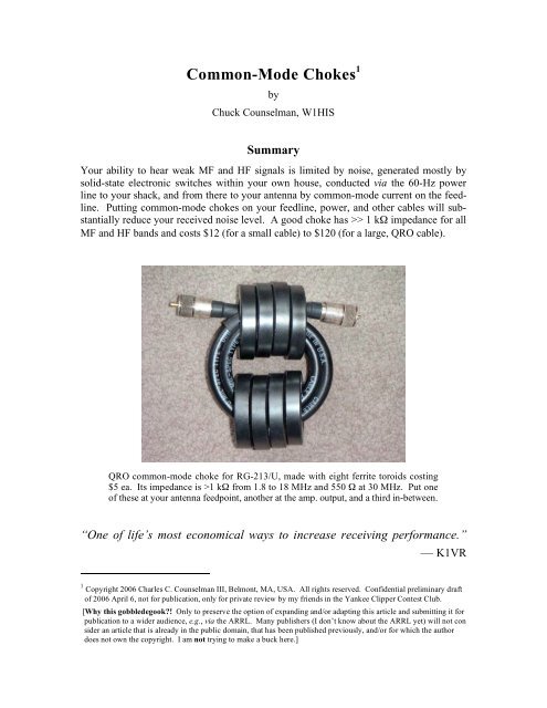
<strong>Common</strong>-<strong>Mode</strong> <strong>Chokes</strong> Confidential draft for YCCC review, <strong>by</strong> <strong>W1HIS</strong> 2006 April 6 Page 3 of 42Figure 4: <strong>Common</strong>-mode choke for high RF power, formed <strong>by</strong> passing RG-213/U coaxial cable through a binocular core formed <strong>by</strong> two stacks of ferritetoroids. This choke’s impedance exceeds 1 kΩ from 1.8 through 18 MHz,dropping to 550 Ω at 30 MHz. COST OF FERRITE: $40 ...................................... 21Figure 5: At upper left, a super-QRO common-mode choke made <strong>by</strong> windingHeliax® LDF4-50 semi-rigid coax on a cylindrical ferrite core. At lower right,the charred remains of a Radio Works T-4 Line Isolator like the one that thisHeliax-wound choke replaced. .................................................................................... 28Figure 6: A 4:1 current balun for 160 through 10 meters, able to handle 1.5 kWwith SWR up to 100. COST OF FERRITE: $30 .................................................... 31Figure 7: Corcom difference-mode EMI filter on base of QRN-generating lamp. ...... 32Figure 8: Corcom and Potter, 30-A, 115/250-VAC, difference-mode, EMI filtersbought at hamfests for $5 each. ................................................................................... 33Figure 9: Potter, 12-A, 115-VAC, difference-mode EMI filter, boxed withduplex outlet, bought at hamfest for $10. ..................................................................... 33Figure 10: 15-A, 120-VAC, multiple-outlet box with built-in difference-modeEMI filter, fuse, switches, and surge protectors. .......................................................... 34Figure 11: 15-A, 120-VAC, multiple-outlet strip with Corcom two-stage, L-C,difference-mode EMI filter and ferrite-bead common-mode choke added. ................... 34Figure 12: 7-A, 115-VAC, two-stage, L-C, difference-mode EMI filter <strong>by</strong>W3NQN, with ferrite toroid and bead common-mode chokes added. ........................... 35Figure 13: <strong>Common</strong>-mode choke for 2 × AWG 4 DC-power cable. ........................... 36Figure 14: <strong>Common</strong>-mode chokes on one 60-A and one 40-A, 240-VAC, 3-conductor, power cables. ............................................................................................. 37Figure 15: <strong>Common</strong>-mode chokes on telephone and computer network cablesplugged into four wall jacks. On the cable plugged into the upper left jack arethree chokes wound on 2.4-inch o.d. ferrite toroids. (Compare Figure 3.) On thecable plugged into the lower left jack are two K-COM modular chokes and onehome-brew, three-turn, bead choke. On the cable plugged into the upper rightjack are one K-COM and one K-Y modular choke. On the cable plugged into thelower right jack are two K-COM chokes. Also visible, at the bottom of thepicture, are three toroidal chokes on power cables. ...................................................... 38Figure 16: K-COM modular four-wire common-mode choke on the handsetcord, and K-Y modular two-wire common-mode choke on the line cord, of atelephone set. Also visible are a toroidal choke on the low-voltage power cable,and a four-bead binocular-core choke on the telephone-line cable of a Caller-IDbox. ............................................................................................................................. 40Figure 17: Above: binocular-core-series common-mode choke in 120-VAC, 6-A,extension cord. Below: toroidal common-mode choke in wall-wart output. ................ 41
<strong>Common</strong>-<strong>Mode</strong> <strong>Chokes</strong> Confidential draft for YCCC review, <strong>by</strong> <strong>W1HIS</strong> 2006 April 6 Page 5 of 42current is equal to the algebraic or “signed” difference between the currents in the twowires, divided <strong>by</strong> two. The common-mode current is the algebraic sum, or net current inthe cable.In another example, imagine connecting the two wires of a piece of zip cord together ateach end, in other words connecting the wires in parallel, to obtain a single conductorable to carry twice as much current as either wire could carry <strong>by</strong> itself. In this zip cord,zero current will flow in transmission-line mode; whatever current flows (depending onthe application) will be common-mode current.In different situations (which you can imagine), non-zero values of current may flow inboth modes: the transmission-line mode and the common mode.RF currents (unlike DC) vary with position along a cable, and their amplitudes are complex(having magnitudes and angles, or real and imaginary parts); however, the conceptsof transmission-line and common-mode apply at any cross-sectional plane; and the complexamplitudes are added and subtracted algebraically.A cable may have more than two conductors. An N-conductor cable has N independentmodes of current flow. Of these modes, the only one that interests us here is the commonmode. For any number of conductors in a cable, the common-mode current is thealgebraic (signed) sum of the currents in all the conductors.A common-mode choke for use in an N-conductor cable has N insulated conductors, onefor each conductor of the cable. An ideal common-mode choke is perfectly transparentin every mode except the common mode. It offers no resistance (or reactance) to anydifferential or transmission-line current; but, for the common mode, it looks like an opencircuit. In other words, the perfect common-mode choke has infinite impedance in thecommon mode.To be perfectly transparent in every mode except the common mode, the common-modechoke must be like the cable in such respects as conductor size and current rating, insulationthickness and voltage rating, and — for an RF transmission line — characteristicimpedance. The simplest way to make a common-mode choke transparent is to make itfrom a piece of the same type of cable. Then, to give the choke a high common-modeimpedance, you surround this piece of cable with ferrite.2.1. FerriteFerrite is a ceramic material, made like pottery or bricks, <strong>by</strong> firing in an oven. Ferritecontains iron and other ferromagnetic elements in oxidation and crystallographic statessuch that the ferrite has high magnetic permeability (µ) and very low electrical conductivity(σ). If a cable is surrounded <strong>by</strong> ferrite, then the magnetic field encircling the cabledue to common-mode current in the cable magnetizes the ferrite. Because the magneticpermeability of ferrite is very much greater than that of air, the amount of energy storedmagnetically in the ferrite is very great. Thus, the inductance per unit length of cable surrounded<strong>by</strong> ferrite is very high. A common mode choke is an inductor having a highvalue of inductance. The impedance (Z) of an inductor is proportional to frequency (f)and is given <strong>by</strong>Z = 2 π i f L,
<strong>Common</strong>-<strong>Mode</strong> <strong>Chokes</strong> Confidential draft for YCCC review, <strong>by</strong> <strong>W1HIS</strong> 2006 April 6 Page 6 of 42in which i is the square root of minus one and L is the inductance. I discuss below howhigh the magnitude of Z must be for the choke to do the job expected of it. In any case,knowing this magnitude and the frequency, you can calculate how much inductance thechoke must have. The inductance is proportional to the energy stored magnetically in thechoke. This energy, in turn, is proportional to the amount (mass or volume) of ferrite inthe choke. The proportionality constant is determined <strong>by</strong> the geometry of the choke, i.e.,<strong>by</strong> the shape of the ferrite and how it fits around the cable. Some geometries are muchmore effective than others, in that they store much more magnetic energy and make amuch higher-inductance (better) choke per unit mass, or per dollar cost, of ferrite.Before getting to geometry, I need to say a few words about ferrite materials. There aremany kinds of ferrite material, made <strong>by</strong> mixing different ingredients together andprocessing (e.g., grinding, cooking, and annealing) the “mix” differently.Different mixes have different properties. To make a common-mode choke for MF andHF (the 160- through 10-m ham bands), I like to use Fair-Rite Products Corp. mix number 31 or 43. Other mixes work better or just aswell in particular applications, and I use other mixes. However, these two are all I need.Actually, either one of these two would do, but mix 31 is more cost-effective for smallerchokes, and mix 43 is more cost-effective for larger chokes, e.g., for the larger coaxialcables needed with high-power transmitters. Using two mixes, 31 and 43, is anengineering compromise.The reason why many different mixes are made is that ferrites are imperfect materials.Some work best at UHF, others at VHF, others at HF, others at MF, and so on downthrough the spectrum, through audio, to DC. Some are very lossy, which is not entirelybad for RFI suppression; whereas others have low loss, which is obviously better in atransformer core. A crucial compromise, or trade-off, involves loss and magneticpermeability.In a common-mode choke we want high permeability, for high stored energy, highinductance, and high common-mode choking impedance with low mass / volume / dollarcost of ferrite. Unfortunately, with high permeability comes high loss. High loss meansthat the choke looks like a low-Q inductor. In other words, it looks like a resistor inseries with a perfect inductor. Current flowing through a resistor dissipates power andmakes heat. In a common-mode choke in the antenna feedline of a 1500-W ham station,dissipation due to common-mode current through an inadequate choke can easily heat theferrite enough to crack it and to melt the cable. A thermal-runaway process occurs,because ferrite loses its ferromagnetism above its so-called Curie temperature. Thechoke’s inductive reactance vanishes, so the choke becomes even more inadequate, andthe common-mode current increases; but the choke’s series resistance does not vanish, sothe dissipation and rate of heating increase.My choices of Fair-Rite Products mixes 31 and 43 are compromises between theconflicting values of low loss, and high permeability. Other mixes have much less loss,and still others have much greater permeability. Mixes 31 and 43 have the highestpermeabilities that you can get, with losses still low enough (if your common-modechoke has sufficiently high impedance, as discussed below) that the common-modecurrent (I) through the choke will be sufficiently small that the power (I 2 R) dissipated in
<strong>Common</strong>-<strong>Mode</strong> <strong>Chokes</strong> Confidential draft for YCCC review, <strong>by</strong> <strong>W1HIS</strong> 2006 April 6 Page 7 of 42the choke’s equivalent series resistance (R) will be sufficiently small and the resultingtemperature rise will not be not unsafe, even if you are transmitting 1500 W.The condition “if your common-mode choke has sufficiently high impedance” here iscrucial. Compromise on choking impedance and your choke will fail catastrophically,taking your coax with it, possibly setting fire to your house, and — worst of all —terminating the best run you’ve ever had, in the most important DX contest of your life.Do not tempt Mr. Murphy. You have been warned.I won’t tell you to use a lower-loss, lower-permeability ferrite because I know youwouldn’t. With lower permeability, you’d have to use more ferrite, which would costmore. I know you wouldn’t spend more money just for safety’s sake. Hams are thecheapest people in the world.I won’t tell you to use anything more lossy than mixes 31 and 43 because I use themmyself. Incidentally, of these two, mix 43 has less loss and is the one I use for higher-RF-power chokes.3. Why Use <strong>Common</strong>-<strong>Mode</strong> <strong>Chokes</strong>?The most common reasons for using common-mode chokes are:(1) to reduce the fraction of the RF power that is fed to your antenna from your transmitter,but then is conducted back to your shack via common-mode current on yourfeedline, causing RFI trouble in the shack or elsewhere in your house;(2) to keep the transmitted RF power that 60-Hz power, telephone, TV, and othercables in the field of your antenna pick up, from bothering susceptible devices connectedto these cables in your own and neighbors’ houses; and(3) to keep the RF noise that all the electronic devices in your house generate, frombeing conducted via 60-Hz power, telephone and other cables to the outer shield of yourradio, and from there along your feedline(s) to your antenna(s), in common-mode.Reasons (1) and (2) are obvious and compelling. When your logging computer crashesor your spouse is screaming, you have to do something. Reason (3) is more subtle andignorable. Even when QRM and QRN are obliterating half the stations on the band —hell, 90% of the signals — you can continue operating and having fun. There are stillplenty of stations strong enough to work. Reason (3) matters only to a serious DXer orcontester, but it is one of the most economical of all ways of improving receivingperformance.A significant fraction, typically -15 dB, of the noise power arriving at an antenna feedpointvia common-mode current on the feedline is coupled into the antenna’s receivingmode, because a typical balun (adequate for transmitting purposes) has this much residualimbalance, and also because a nominally balanced antenna is never perfectly balanced.A common-mode choke is reciprocal. It reflects and absorbs transmitted power thatwould otherwise be conducted from your antenna back to your shack and onto your 60-Hz power and other circuits to bother, say, your telephone, <strong>by</strong> the same factors ornumbers of dB as it does for QRN going in the opposite direction.
<strong>Common</strong>-<strong>Mode</strong> <strong>Chokes</strong> Confidential draft for YCCC review, <strong>by</strong> <strong>W1HIS</strong> 2006 April 6 Page 8 of 42If your antenna is highly directional, as a Yagi or a Beverage is, then you have anotherreason to use a common-mode choke: to prevent reception of QRM and QRN <strong>by</strong> yourfeedline as opposed to your antenna. Without a good common-mode choke in the feedlineat its feedpoint, your potentially excellent antenna’s 25- or 30-dB front-to-back orfront-to-side ratio could be reduced to 15 or even 10 dB.In the HF hamshacks that I’ve visited, the background noise level heard on most HFbands (especially the low bands) could be reduced <strong>by</strong> more than an S-unit <strong>by</strong> means ofcommon-mode choking. In some cases (which I could name but won’t, to avoid embarrassingmy friends) I was able to reduce the received noise level <strong>by</strong> four or five S-units. Ireduced my own received noise level on the low bands <strong>by</strong> even more.For years I’ve been a regular participant in CW nets on the 80- and 40-m ham bands, andin SSB nets on MARS frequencies near these bands. I hear better than anyone else inthese nets. I am often the only participant able to copy every one of the dozen or twodozen stations in a net. Why can I hear so exceptionally well? My receiver is nothingspecial, nor is my antenna; it’s a wire just 23 to 40 feet high. Nor is my QTH very quiet.I have a small lot in a dense suburb, just two miles from Cambridge and three miles fromBoston. I hear exceptionally well because I have good common-mode chokes in myantenna feedline, in the other cables connected to my radio, and also in the cables connectedto the worst of the QRN sources in my house.A typical American household contains more than a hundred significant QRN sources.Some of these sources, e.g., incandescent light dimmers, fill the MF and HF spectrumwith noise in periodic bursts or impulses at the 60-Hz power-line frequency (or at 120Hz). In a SSB receiver (even more in an AM receiver) this noise sounds like a steadybuzz, and its strength doesn’t change if you tune a few tens of kHz.Switching power supplies, which are in all kinds of electronic appliances, in the batterychargers of portable devices, in the solid-state electronic “ballasts” of fluorescent lamps,and in the “solid-state transformers” of low-voltage incandescent lighting systems, generaterelatively narrow-bandwidth, hum-modulated, QRN at harmonics of their switchingfrequencies, usually in the 15-25 kHz range. These frequencies are not very stable, butdrift and fluctuate with temperature, power-line voltage, and load current.Digital-electronic circuitry is ubiquitous (not just in computers) and usually switches atstable frequencies. Digital electronics generates QRN most often with discrete spectraand quasi-periodic, often complex, but regular temporal structure. However, somedigital-electronic sources of QRN have very broad spectra, or spectra with such broadpeaks, that the QRN can be mistaken for natural “white” noise in a communicationsreceiver. Also, the typical house contains so many independent sources of QRN that,although their individual spectra may be peaky, the composite spectrum can sound prettyflat.Many or most of these sources continue to generate QRN even when the appliance ordevice is switched “off.” Many of them, e.g., video and audio entertainment devices,computers and related devices, telephones and related devices, clocks and timers in allsorts of devices, and (probably worst of all) alarm systems, contain batteries or supercapacitorsand continue to generate QRN even after AC power is disconnected <strong>by</strong> unplugging the device/system or flipping a circuit-breaker.
<strong>Common</strong>-<strong>Mode</strong> <strong>Chokes</strong> Confidential draft for YCCC review, <strong>by</strong> <strong>W1HIS</strong> 2006 April 6 Page 9 of 424. Where to Use <strong>Common</strong>-<strong>Mode</strong> <strong>Chokes</strong>Most hams would benefit from installing common-mode chokes in many places. I suredid! I had to install a couple of chokes before I could transmit even low power on 15meters without triggering a fire alarm. When I got an amp, I could trigger the alarm <strong>by</strong>transmitting on any of several bands. Installing more chokes, in more places, solved thisproblem.When I first moved into my present QTH, even before I began hamming here, I had toinstall several common-mode chokes to stop hearing loud audio QRM in my telephones,from the amplitude modulation of two near<strong>by</strong> broadcast stations. In addition to musicand speech, in certain ’phones I also heard a constant hum or buzz, because the broadcastcarrier signals were being 60-Hz-AC-modulated <strong>by</strong> nonlinear conductors within myhouse. A long story, with a happy ending thanks to more common-mode chokes.My QRO HF TX got into the telephones and whole-house audio entertainment system ofmy neighbors across the street. Fortunately for me, their telephones and computer modemswere already being clobbered <strong>by</strong> the local AM broadcast stations. Solving thoseproblems made me a hero. I solved all of my neighbors’ RFI problems with commonmodechokes. Along the way, I installed a few more common-mode chokes to eliminatethe QRN I’d been hearing from the solid-state transformers in their low-voltage lightingcircuits.In my own house and yard I’ve installed many, many common-mode chokes to eliminateQRN from many, many, many(!) light-dimmers, compact fluorescent lamps, electricblanket controls, computers, computer peripherals and networking devices, TV sets,VCRs, garage-door openers, etc. One of the worst QRN sources in my house, until Imuted it with common-mode chokes, was the intrusion- and fire-alarm system.An unbelievably large number of small and seemingly innocuous devices, like thebattery-recharging base of my cordless electric toothbrush, and a tiny 4-watt night-light(photoelectrically switched), were generating noxious QRN. Our air bed’s control systemwas both a source and a victim of RFI. Its variable-speed pump pulsed in response tothe syllables of “Whiskey One Hotel India Sierra” when I worked 3YØX on 20-m SSB.As Don Greenbaum remarked, I was a lucky ham to have an XYL who got pumped up <strong>by</strong>my DXing.Your HF noise background is almost certainly being raised, and your ability to hear weaksignals is being impaired, <strong>by</strong> the noise generated <strong>by</strong> electrical / electronic devices in yourhouse. Unless you’ve sniffed around with a shielded, B-field-sensing loop and a batterypoweredHF receiver as I have, 2 you probably don’t know what or where most of theseQRN sources are. I was amazed <strong>by</strong> how many I found in my own house. As soon as Isilenced one (with a common-mode choke), I could hear another, which I located andsilenced in turn. With each additional common-mode choke (or trashing of the offendingdevice), my received noise level dropped lower.2 Appendix 2, to be included in a future draft of this article, will address noise-sniffing.
<strong>Common</strong>-<strong>Mode</strong> <strong>Chokes</strong> Confidential draft for YCCC review, <strong>by</strong> <strong>W1HIS</strong> 2006 April 6 Page 10 of 42So here’s where to put common-mode chokes:First,• on a coaxial feedline near the feedpoint of any antenna; or, if you run balanced linefrom the feedpoint of a balanced antenna to a balanced tuner and balun (or balun andunbalanced tuner) at, say, the point of entry to your house, on the coax at this point; 3• on a coaxial feedline on both sides of any point where the coax shield is connected toa rod or pipe driven into the ground, or to a counterpoise; 4• on a coaxial feedline in your shack, where the coax first reaches your tuner, amp, ortransceiver;• on a long coaxial feedline, at intervals of one-quarter wavelength; 5• on any other cable that goes near your antennas, e.g., to a rotator, to a remote tuner orrelay/switchbox, to SteppIR motors, to tower lights or utility outlets, …;• on the power cable at an outdoor compact fluorescent lamp if this cable runsanywhere near your antennas, and also where this cable enters your house;• on both the high- and the low-voltage sides of any solid-state transformer that feedslow-voltage lighting near your antennas;• at the ground-fault circuit interrupter (GFCI) of any AC power circuit that goes nearyour antenna. 6Second,• on every 60-Hz AC power cable that feeds your shack; 7• on every other cable (antenna-rotator, telephone, TV, computer network, etc.) thatcomes into your shack;• on every cable of every computer, peripheral, keyer, TNC, switching power supply(including wall warts and battery chargers, especially laptop-computer power adaptors)and other device connected to your radio that oscillates, switches, or digitates;3 An effective common-mode choke can made for a balanced feedline as well as for coax. For example, seethe common-mode chokes on the 100-Ω balanced lines in the 4:1 current balun described in Appendix 4.4 The low-pass T-network formed <strong>by</strong> two chokes with a “ground” between them is significantly moreeffective than the same chokes would be without the ground, and much more effective than the groundalone would be.5 Two common-mode chokes separated <strong>by</strong> a quarter-wavelength work better than the same two chokes inseries, together in one place, because reflection of the common-mode wave <strong>by</strong> the high-Z lump posed <strong>by</strong>one choke causes an impedance minimum to appear one-quarter wavelength away. N (>2) chokes distributedover a quarter wavelength work better than the same N chokes bunched together in one place.6 By code, every outdoor circuit must have a GFCI. RF can trip these devices. Worse, some of thesedevices generate QRN. Some even generate QRM! In my house one was generating strong intermodproducts, in the 160- and 80-m ham bands, from the signals of local AM broadcast stations. (Replacingthis GFCI with a new one eliminated the problem.)7 You may have more than one 120-V branch circuit, plus a 240-V circuit for your amp. Each of thesecircuits should also have an L-C, difference-mode, EMI filter. See Appendix 5.
<strong>Common</strong>-<strong>Mode</strong> <strong>Chokes</strong> Confidential draft for YCCC review, <strong>by</strong> <strong>W1HIS</strong> 2006 April 6 Page 11 of 42• on the AC line cable/cord of any compact fluorescent lamp or any incandescent lampwith a dimmer and/or solid-state transformer that is plugged into your shack circuits. 8Third,• at any identified QRN source in or around your house; 9• on the cables of an intrusion / fire / other alarm system, at panels, multiplexers,telephone-line interfaces, radio-telemetry interfaces, 60-Hz power supplies, stand<strong>by</strong>battery charger / supplies, etc.;• on TV cables, both where they enter your house and where they reach TV sets,converters, VCRs, DVRs, cable modems, etc.;• on 60-Hz AC power cables and any audio and video cables connected to TV sets,music and “home theater” systems, etc.; 10• on telephone cables, both where they enter your house and where they reach telephonesets, answering machines, cordless base stations, ADSL modems, ISDNmodems, POTS modems, etc.; and on all power cables (e.g., from wall warts)connected to telephone-line-connected equipment; also on the handset cords oftelephone sets. 115. How Good is “Good Enough”?Just to reduce the severity of a noise or RFI problem (but probably not to eliminate it), acommon-mode choke should have at least 1 kΩ (1000 ohms) impedance at the relevantfrequency. Here I refer to the magnitude of the impedance. The angle of the impedanceis important only if the choke is in a transmitting antenna feedline and the magnitude ofthe impedance is too small, so that too much common-mode current flows through thechoke and I 2 R dissipation heats it.As mentioned previously, the chief trade-off in the design of a common-mode choke isbetween choking impedance and power-handling ability. The next several paragraphsillustrate this point.8 Old-fashioned fluorescents with iron ballasts, especially ones with neither rapid starting nor neon-lampbasedstarters, are RF-quiet. New-fangled incandescents with dimmers (e.g., quartz-halogen “torchiere”floor lamps) and low-voltage quartz-halogen desk lamps with solid-state transformers are very loud; theseneed L-C difference-mode power-line filters as well as common-mode chokes. See Appendix 5.9 See §§ 3 and 4 above for examples. In addition, beware of variable-speed motor controls (e.g., inwashing machines and treadmills), electronic door-chime systems, and irrigation sprinkler controlsystems. In the latter systems, put a common-mode choke on every cable at the electronics box, andanother at the power transformer. A switcher, as opposed to an old-fashioned iron transformer, needschokes on both sides.10 Remember that RF picked up <strong>by</strong> a loudspeaker cable, which you might regard as a high-level circuit, canbe coupled to a sensitive low-level stage via linearizing feedback circuitry in an audio power amplifier.11 Telephone equipment tends to be more susceptible to RFI than anything else in an American house. Tocure RFI in a telephone or telephone-related device, a common-mode choke often needs to have threetimes the impedance needed to cure any other RFI problem. Fortunately, these are low-power and smallcableapplications, so even very, very good chokes are cheap. See Appendix 5 for examples.
<strong>Common</strong>-<strong>Mode</strong> <strong>Chokes</strong> Confidential draft for YCCC review, <strong>by</strong> <strong>W1HIS</strong> 2006 April 6 Page 12 of 42Why at least 1 kΩ?There are at least four ways to answer this question:First, on the basis of experience: Much less than 1 kΩ seldom solves a problem. Toooften, 1 kΩ does not. Often, you need 3 kΩ. Sometimes you need 6 kΩ.Second, <strong>by</strong> seeing what others do: A well-known (perhaps I should say notorious) commercialcommon-mode-choke for 50-ohm coaxial transmission lines is Radio Works’“T-4 Line Isolator.” Radio Works’ performance claims for this choke are fantastic, butthey are pure fantasy. Its inductance is only 21 µH; the magnitude of its impedance isonly 522 Ω at 4 MHz, and it is greater than 1 kΩ for only the 10- to 21-MHz ham bands.Radio Works recommends using two of these chokes in a station. I tried two 12 and foundthem inadequate. Worse, both failed while I was transmitting less than 1500 W. 13 It wasmy bad experience with these chokes that motivated me to learn how to make my own.Joe Reisert, W1JR, makes his own 50-ohm coaxial common-mode chokes <strong>by</strong> winding 12turns of RG-303 (0.17-inch o.d., PTFE dielectric) coax on a single 2.4-inch (o.d.) ringshapedtoroid of Fair-Rite Products ferrite mix 61. The impedance of one of these chokesis about 500 Ω ohms at 3.5 MHz and greater than 1 kΩ for 7 through 30 MHz. I don’tknow how many of these chokes he puts in a feedline. This choke appears safe for legallimitpower if (and only if) the SWR in the transmission-line mode is low and the chokeis well ventilated. With power = 1500 W, SWR = 1, and f = 28 MHz, the power dissipatedin the relatively compact coaxial winding (not in the ferrite) is 10 W.Walt Maxwell, W2DU, made a 50-ohm coaxial common-mode choke (which he called a“bead balun”) <strong>by</strong> stringing a large number of ferrite beads on a straight length of coax.According to tests reported on <strong>by</strong> Tim Duffy, K3LR, theimpedance of the original W2DU choke was marginal, and — worse — even with a 50-ohm resistive load (unity SWR), the choke overheated at 500 W on every band. A betterbead balun was developed <strong>by</strong> WØIYH, who strung 100 ferrite beads of Fair-Rite Productsmix 43, with dimensions (I think but I’m not certain) o.d. 0.562 in., i.d. 0.250 in.,length 1.125 in. (per bead) on 10 ft.(!) of RG-142 (0.195-inch o.d., PTFE dielectric) coax.K3LR measured the impedance of one of these chokes to be:Freq. (MHz)|Z| (Ω)1.8 11523.7 34837.1 411514.2 178321.2 128028.5 123412 In the coaxial line from my amp. to my remote unbalanced tuner, which was followed <strong>by</strong> a 4:1 balun.One choke was at the amp. output; the other was at the tuner input, 70 ft. away.13 Radio Works claims that these chokes handle greater than 1500 W below 28 MHz. The chokes that Iwas using failed due to resistive heating of the small-diameter coaxial-cable winding <strong>by</strong> transmissionline-modecurrent (exacerbated <strong>by</strong> thermally insulating packaging), not due to heating of the ferrite <strong>by</strong>common-mode current. Many other failures have been reported on and.
<strong>Common</strong>-<strong>Mode</strong> <strong>Chokes</strong> Confidential draft for YCCC review, <strong>by</strong> <strong>W1HIS</strong> 2006 April 6 Page 13 of 42K3LR reported that the WØIYH choke got warm but did not overheat on any band at2000 W with SWR = 1. K3LR has three of these chokes in each of his antenna feedlines.One choke is at the antenna feedpoint, another is at the tower-mounted antennaswitch box, and another in the shack where the coax connects to the power-amplifier.Third, <strong>by</strong> observing that it is not expensive or difficult to make and install a 1-kΩ choke,and concluding from this observation that anything less is not worth bothering with.Fourth, <strong>by</strong> this calculation: The characteristic impedance, Z o , of the unbalanced transmissionline formed <strong>by</strong> one conductor having a circular cross-section, and parallel to aninfinite horizontal ground-plane, in air, is given <strong>by</strong>Z o = 138 Ω • log 10 (4h/d),where h is the height of the conductor and d (
<strong>Common</strong>-<strong>Mode</strong> <strong>Chokes</strong> Confidential draft for YCCC review, <strong>by</strong> <strong>W1HIS</strong> 2006 April 6 Page 14 of 426. How to Make <strong>Common</strong>-<strong>Mode</strong> <strong>Chokes</strong>This section describes how to make chokes having impedances of about 1000 Ω throughoutthe MF and HF ham bands. It’s foolish to make anything less; and, as just discussed,it’s not unusual to need 3 to 6 kΩ. To get 3 to 6 kΩ, string three to six 1-kΩ chokes inseries. Do not wind/thread more turns of cable on/through the same amount of ferrite!If you did this, your choke would have much less than 1-kΩ impedance on the higherbands.The chokes described in this section are effective for all bands from 160 through 10meters. They are most effective for 40 m and very good for 80 and 20 m. For 160 m,their finite inductance limits their impedance. For 10 m, inter-turn capacitance limits theimpedance. Their self-resonant frequencies, at which their parallel inductive and capacitivereactances have equal magnitudes, are in the neighborhood of 10 to 14 MHz.However, the resonance is very broad because the ferrite of choice is quite lossy, asdiscussed in §2.1.If 100% of your operating is on a single band, then a choke having a sharper resonanceand resonant at that band could be more cost-effective for you. 14 However, a sharplyresonant choke should not be used in the feedline of a single-band antenna at a stationthat also has an antenna for another band, because (1) RF power transmitted <strong>by</strong> one antennacan return to the shack via common-mode on the feedline of another antenna; 15 and(2) QRN generated within your house and carried <strong>by</strong> common-mode on one feedline canbe coupled to another feedline, especially if these feedlines run parallel for a way. Be-14 A coil of coax on an “air” core (with no ferrite) has a fairly sharp (in other words, high-Q) resonance andcan be a good choke for a single band. Ed Gilbert, WA2SRQ, has published impedance measurementdata on for coiled-coax, air-core, chokes of various sizes and shapes. Hefound that >1 kΩ impedance could be obtained for one-octave bandwidth. However, high-Q chokes andespecially air-core chokes have significant problems that a high-Z, but low-Q, ferrite-core choke does nothave: (i) a high-Q choke must be tuned; (ii) an air-core choke is easily detuned <strong>by</strong> proximity to a conductingobject; (iii) interaction between two or more high-Q chokes or other resonators, deliberate or accidental, in the same feedline can interact to shift the resonant frequencies; and (iv) a high-Q choke does notabsorb, or damp, common-mode waves; it merely reflects them and redistributes the frequencies of the“normal modes” (i.e., the frequencies at which the entire system resonates). For RFI suppression, it helpsto have damping.15 The coupling between widely separated antennas can be surprisingly strong. (One suspects that resonancesare at work.) My HF antenna is horizontal, symmetrical, balanced, in the clear, broadside to and 100feet away from my 2-m antenna, which is vertical and also in the clear. Thus, the polarizations of theseantennas appear quite orthogonal and one does not expect much cross-coupling. At each end of the coaxialfeedline of each antenna is good common-mode choke. The chokes in the 2-m feedline are good notonly for 144 MHz but also for HF. Yet, when I transmit high power at 14 MHz, the broadband directionalcoupler at the shack end of the 144-MHz feedline indicates a few watts of power. (A four-cavity,2-m bandpass filter reflects this14-MHz power before it reaches the input of my 144-MHz receiver.) Thisindication occurs when I transmit on 14 MHz but not any other HF band. I suspect that my 2-m verticalantenna, in combination with the mast and lightning-safety ground below it, and coupled to the transmission-linemode of its low-loss (Heliax LDF4-50) feedline, which is terminated losslessly at 14 MHz <strong>by</strong>the 2-m filter, has a high-Q resonance at 14 MHz. I have not experimented deliberately to confirm thishypothesis, but the appearance of HF power in the 2-m feedline coincided with my installation of the 2-mfilter, which would have shifted the resonant frequency. I suspect also, but again have not confirmed, thatthe primary mode of HF propagation to my 2-m antenna is ground-wave, guided <strong>by</strong> the soil-air interfacerather than common-mode current on my feedlines or other cables.
<strong>Common</strong>-<strong>Mode</strong> <strong>Chokes</strong> Confidential draft for YCCC review, <strong>by</strong> <strong>W1HIS</strong> 2006 April 6 Page 15 of 42cause I doubt that many YCCC members limit their operations to a single band, I do notdiscuss single-band chokes in this article.In this §6 I describe three kinds of choke: one appropriate for low to medium RF poweron a thin cable; one for low to medium RF power on a thin cable with fat connectorsattached; and one for high RF power on a thick cable. Some other designs are describedin Appendices 3, 4, and 5. Over time, I hope to add descriptions of still others.I assume that you have the cable or know how to get it. Ferrite, however, is relativelyhard to get — surprisingly so in view of its utility in ham radio. So I’ll tell you how tobuy ferrite. I’ll also try to organize a group purchase of ferrite at the YCCC meeting onApril 8, 2006, and via .6.1. How to buy ferriteI buy surplus ferrite on eBay and at hamfests whenever I can, but these opportunities aretoo random and tricky to describe usefully. At a hamfest, you can see and feel whatyou’re buying. However, seeing and feeling aren’t enough because there are many ferritemixes and you can’t distinguish them without electromagnetic measurements. So I carryan HF complex-impedance bridge and wire for winding on ferrite components, tomeasure them. A brief description of how I do this is given in Appendix 1.I buy new ferrite components in quantity from:Lodestone Pacific, 4769 E. Wesley Drive, Anaheim, CA 92780Tel. 800-694-8089 or 714-970-0900; fax 714-970-0800Email Web WARNING: Lodestone Pacific is a big wholesaler, not a retailer. Do not ask them tohelp you figure out what you want. However, if you know exactly what you want, do notask for information about a product, do not ask for advice, and in general do not wastetheir time, they will talk to you, they will be very nice, they will sell you a modestquantity, and they will even charge your credit card. Their prices are less than half, oftenmuch less than half, those of any company that advertises in QST.BEFORE calling Lodestone Pacific or even looking at their website, you must be familiarwith the catalog of the ferrite manufacturer, Fair-Rite Products Co. .The 15 th edition of this catalog, a fantastic 722-page document, is downloadable free, asan 8.2-MB PDF file, from.With this catalog at hand, search the list of remainders / clearance items at LodestonePacific’s website. You will find incredible bargains if you know what the ten-digit Fair-Rite part numbers mean and can recognize that a clearance item can be substituted forwhat you originally wanted.For choking thin cables at low to medium RF power, I use:Fair-Rite p/n 2631102002 (a “round cable suppression core,” a.k.a. “bead,” of ferritemix 31, with dimensions 1.020" o.d., 0.505" i.d., 1.125" long), unit price $ 0.9635 inthe lot of 264 that I bought 3/24/2005.
<strong>Common</strong>-<strong>Mode</strong> <strong>Chokes</strong> Confidential draft for YCCC review, <strong>by</strong> <strong>W1HIS</strong> 2006 April 6 Page 16 of 42For choking thick cables or thin cables with fat connectors, I use:Fair-Rite p/n 5943003801 (a ring-shaped toroid of mix 43, 2.400" o.d., 1.400" i.d.,0.500" tall / thick), unit price $ 4.58 in the lot of 50 that I bought 3/24/2005.6.2. Thin cable, low to medium RF powerThis section describes a very simple and inexpensive choke made <strong>by</strong> threading a thincable three times through a “binocular” core formed <strong>by</strong> two Fair-Rite p/n 2631102002,mix-31, beads side-<strong>by</strong>-side like the tubes of binoculars.This is a cost-effective choke for any round cable of o.d. 0.2" or less, or “zip cord” of size2 × AWG 16 or less — e.g., small 120- and lower-voltage power cords, telephone cords /cables, computer cables, and coaxial cables for receiving or for transmitting HF power upto 100 W, more or less, depending on cable material and construction. The safe powerlimit is determined <strong>by</strong> a combination of thermal issues and the mechanical stress caused<strong>by</strong> the curvature of the cable in the choke. The radius of this curvature is about 0.5 inch.RG-58/U coax, in which the center conductor is solid copper and the dielectric is solidpolyethylene, is probably safe for 100 W in this choke. RG-58A (Belden 8259) or RG-58C (Belden 8262), in which the center conductor is flexible (stranded, not solid) and thedielectric is also solid (not foamed) polyethylene, is probably safer. In a cable having asolid center conductor, and especially in a cable having foamed dielectric, the centerconductor is more able to mush through the dielectric and short to the shield if the centerconductor is heated <strong>by</strong> too much RF current.Manufacturers of RG-58-type cables typically specify a minimum bending radius of 2.0inches. Subject to this bending limit, and for an ambient temperature of 40°C (104°F),RG-58-type cables are rated to carry about 500 W at 14 MHz with SWR = 1. Unfortunately,I don’t know how any of these cables should be derated for sharper bending. I knowonly that, for a given transmitted power, the power dissipated in the center conductor isproportional to the square root of frequency; and that, for SWR > 1, the power dissipatedat a maximum of the standing wave in the transmission-line-mode current is magnified<strong>by</strong> a factor of the square root of the SWR. Thus, for example, at 28 MHz with SWR = 4,the transmitted-power limit for RG-58-type cable is reduced to 175 W — before anyallowance for bending-radius < 2.0 inches. So be careful. Don’t use this common-modechoke (or any device) in a transmitting feedline where it could start a fire <strong>by</strong> shorting andarcing. Remember that polyethylene, and many cable jacket materials, are flammable.For higher transmitted power, some hams have suggested using RG-303 (Belden 84303)coax in this choke. RG-303 has PTFE dielectric, which remains solid (although soft) upto a significantly higher temperature than polyethylene does. RG-303 also has a largercenter-conductor than RG-58A or C has (AWG 18 vs. 20). This center conductor is solid,not stranded. However, as previously mentioned, W1JR has wound RG-303 on ferriterings having 0.5" square cross-sections (so the inside radius of curvature of the coaxwould be 0.35"), and (AFAIK) he has not reported a failure at legal-limit power.The choke described in this section would be my first choice for all kinds of smalldiametercable (including telephone cables or “cords”; serial-data, USB, FireWire,10Base-T Ethernet and other computer cables; and low-voltage or 120-VAC power
<strong>Common</strong>-<strong>Mode</strong> <strong>Chokes</strong> Confidential draft for YCCC review, <strong>by</strong> <strong>W1HIS</strong> 2006 April 6 Page 17 of 42cables or “cords”), except that most of these cables come with plugs or connectorsattached that will not fit through the 0.505" hole of a number 2631102002 bead (at least,not if two passes of cable are already in the hole). However, this choke is so inexpensivethat, to use it, sometimes I cut a cable and either splice it or install a new connectorafterward. Splicing is not so bad if you have appropriate heat-shrink tubing.Figure 1, below, is a photograph of one of these two-bead “binocular” chokes threadedwith three turns of RG-58/U coax together with (in parallel with) a 4 × AWG 24 “indoor”telephone cable. I made this choke for W1OUN, whose remote automatic antenna tunerrequired two conductors for 12-VDC power and two for control.Figure 1: <strong>Common</strong>-mode choke for the parallel combination of an RG-58/Ucoaxial cable and a four-wire telephone-type cable. The cables make three turns,or passes through, a “binocular” core formed <strong>by</strong> two Fair-Rite p/n 2631102002beads. The impedance of this choke is greater than 1 kΩ from 1.8 MHz through20 MHz.The magnitude of the common-mode choking impedance of this choke is greater than1 kΩ from 1.8 MHz to 20 MHz. At 30 MHz it is 640 Ω. With just one cable (either the
<strong>Common</strong>-<strong>Mode</strong> <strong>Chokes</strong> Confidential draft for YCCC review, <strong>by</strong> <strong>W1HIS</strong> 2006 April 6 Page 18 of 42coax or the telephone cable) on the same core, the impedance was 1 kΩ or greater from1.8 MHz to 23 MHz. 16As previously discussed, several chokes like this one should be strung together in seriesto obtain sufficient common-mode choking impedance. A six-choke string that I madefor W1OUN is shown in Figure 2.Figure 2: A series string of six binocular-core units like the one shown inFigure 1, on the parallel combination of an RG-58/U coaxial and a 5 × AWG 26tuner-control cable. Three of the six unit chokes were wound with three turns;and three have 2 ½ turns.The remote-tuner power and control cable in this six-choke string has five conductorsbecause W1OUN added a relay to his tuner. In Figure 2 you can see that I omitted ahalf-turn in three of the “unit” chokes. I did this hoping to increase the choking impedanceat 30 MHz, at the expense of impedance at 1.8 MHz. It’s not clear that any improvementresulted. The measured impedance of a 2 ½-turn choke at 1.8 MHz was 70016 The impedance (or admittance) at the high-frequency end is limited <strong>by</strong> inter-turn capacitance, whichobviously is less with thinner or fewer conductors in the winding. When winding any choke, it helps notto cross turns.
<strong>Common</strong>-<strong>Mode</strong> <strong>Chokes</strong> Confidential draft for YCCC review, <strong>by</strong> <strong>W1HIS</strong> 2006 April 6 Page 19 of 42Ω, and I could detect no difference at 30 MHz. At 30 MHz, even 2-inch leads havesignificant capacitance, and my Autek VA-1 bridge 17 is at the limit of its usefulness.6.3. Thin cable with fat connectors attached (low to medium RF power)When a thin cable has fat plugs or connectors attached and I don’t want to cut and splicethe cable or install a new connector, instead of using a two beads to form a binocular coreI use a single Fair-Rite p/n 5943003801, ring-shaped toroid of mix 43, 2.400" o.d., 1.400"i.d., and 0.500" tall / thick, as a core. The cost of ferrite is greater <strong>by</strong> a factor of 2.6, butthe performance is almost is good, and the hole is much bigger.For an HF choke I wind 12 to 14 turns on one of these toroids, as the thickness of thecable permits. Twelve turns is better if you care more about the high bands; 14 is betterfor the low bands.Figure 3, below, shows such a choke, with 13 turns, in the low-voltage 60-Hz AC outputcable (2 × AWG 20 zip cord) of the wall-wart transformer that powers my ADSLmodem. Note the space between the beginning and the end of the winding. This space isnecessary to reduce the capacitance between the ends, which limits the choking impedanceat the highest frequencies.Figure 3: A wall-wart transformer for a modem, with a toroidal-core commonmodechoke in its zip-cord, low-voltage, output cable. Near the other end of thiscable, just before the modem, is another choke like this one.17 See Appendix 1.
<strong>Common</strong>-<strong>Mode</strong> <strong>Chokes</strong> Confidential draft for YCCC review, <strong>by</strong> <strong>W1HIS</strong> 2006 April 6 Page 20 of 42I put two such chokes in this cable. I put a string of three such chokes in the telephonelinecable connected to this modem, 18 and I put a string of binocular-core chokes in the10Base-T Ethernet cable also connected to this modem. The telephone cable, whichextends through my house and outside, passing under one end of my HF antenna on itsway to the street, has several more chokes along the way. The wall-wart plugs into amultiple-outlet box with a computer and other peripherals. Additional common-modechokes and an L-C, difference-mode, filter are in the three-conductor cable feeding 120-VAC power to this box. 19 The Ethernet cable goes to the computer and is short. Everyother cable connecting this computer to the world beyond (e.g., the telephone cable to itsPOTS modem and the telephone cables to its ISDN modem) also contains multiplechokes, at intervals.The impedance that I measured for a single toroidal choke like the one in Figure 3, buthaving 14 turns of 2 × AWG 20 zip cord, was greater than 1 kΩ from 1.1 MHz through26 MHz, but dropped to 340 Ω at 30 MHz.6.4. Thick cable (including coax for high RF power)For thicker cables of up to 0.5" diameter, e.g., RG-213/U coax and 3 × AWG 14, 60-Hzpowercords, it is feasible to string enough 2631102002 beads on a straight cable to makea good choke. A string of 22 of these beads has >1 kΩ impedance from 1.8 MHz throughat least 20 MHz and probably well beyond 30 MHz. 20 For sufficient choking impedanceyou should string more beads on the cable; e.g., 110 beads would yield >5 kΩ from 1.8 toat least 20 MHz 21 and would cost about $110.A choke having about the same common-mode choking impedance and power-handlingcapability in transmission-line mode as twenty-two #2631102002 beads on RG-213/U,but less vulnerable to heating <strong>by</strong> common-mode current, can be made <strong>by</strong> stacking Fair-Rite p/n 5943003801, mix-43 toroids to form a pair of “binocular” tubes each 2.400" o.d.,1.400" i.d., and 2.0" long, and threading RG-213/U through this core three and one-halftimes as shown in Figure 4. (This may be done with PL-259 connectors already attachedas shown.)18 See Figure 15 in Appendix 6.19 See Figure 10 in Appendix 5.20 As discussed in Appendix 1, I am not confident of my ability to measure high impedances (with magnitudesexceeding about 500 Ω) at high HF frequencies (exceeding about 20 MHz). It is especially difficultto measure such impedances meaningfully when the size of the device being measured is greater than afew inches. In the latter case, a two-plane transmission-line measurement should be made, not a twoterminal(single-plane) measurement. I am not presently equipped for two-plane measurements. However,one may extrapolate from measurements of a short string of beads. For example, the magnitude ofthe impedance of a 2" long <strong>by</strong> 1" wide “hairpin” of cable loaded with just two 2631102002 beads, one oneach leg, as measured <strong>by</strong> my Autek VA-1 bridge, is 100 Ω at 1.8 MHz, 300 Ω at 20 MHz, and 250 Ω at30 MHz. At this rate, 22 beads provide 2.8 kΩ at 30 MHz. The most excellent aspect of a longstring-of-beads choke is that (if it is straight, not coiled) one end is far from the other; so itsperformance is not limited <strong>by</strong> capacitance between its ends.21 Compare the WØIYH choke described in §5. Note that RG-213/U has half the loss of RG-303 and safelyhandles more RF power.
<strong>Common</strong>-<strong>Mode</strong> <strong>Chokes</strong> Confidential draft for YCCC review, <strong>by</strong> <strong>W1HIS</strong> 2006 April 6 Page 21 of 42Figure 4: <strong>Common</strong>-mode choke for high HF power, formed <strong>by</strong> passing RG-213/Ucoaxial cable 3½ times through a binocular core formed <strong>by</strong> two stacks of fourFair-Rite p/n 5943003801, mix-43, toroids. This choke’s impedance exceeds1 kΩ from 1.8 through 18 MHz, dropping to 550 Ω at 30 MHz. One such chokeshould be installed at the antenna feedpoint, one at the amplifier output, and atleast one other in-between.The cable, whose total length is 36", passes four times through the upper tube and threetimes through the lower. The magnitude of the common-mode choking impedance of thischoke exceeds 1 kΩ from 1.8 through about 18 MHz. At 25 MHz, I measured 700 ohms;and, at 30 MHz, 550 ohms.By slightly loosening the turns of the coax and not requiring the toroids to be stacked asneatly as I arranged them for this picture, 22 the number of toroids can be increased to 12and the impedance of the choke will be increased <strong>by</strong> 50% at low frequencies, but notchanged much at the high end. 2322 There is no reason to stack them neatly, and there is a reason not to: the toroids should be loose so thatair can circulate between them, for convective cooling. For the same reason, the turns of the cableshould not be tied or taped together, and the entire assembly should not be enclosed.23 At my station I have just one antenna, an inverted-U doublet, for all bands 160 through 10 m. Open-wireline extends from the feedpoint of this antenna to a balanced, remote-controlled tuner. Within this tuneron the TX side is a common-mode choke comprising a bifilar winding of PTFE-insulated, AWG 10,silver-plated copper wire on a large, solid, cylindrical, ferrite core. Next, connected to the 50-Ω coaxial
<strong>Common</strong>-<strong>Mode</strong> <strong>Chokes</strong> Confidential draft for YCCC review, <strong>by</strong> <strong>W1HIS</strong> 2006 April 6 Page 22 of 426.5. Other possibilitiesBy presenting this handful of specific choke designs, I hope(1) to enable hams who lack instrumentation for measuring common-mode current and/orimpedance to build chokes that work better, and cost less, than commercially availablechokes;(2) to suggest issues and possibilities to hams who have instrumentation but have notexperimented with common-mode chokes; and(3) to sensitize everyone to the major issues and trade-offs relating to(a) common-mode-choking impedance at high and low frequencies;(b) power dissipation in the cable due to transmission-line-mode current,and in the ferrite due to common-mode current; and(c) ferrite material and geometry.In response to continuing questions and comments from readers I hope to revise thisarticle to make it more useful.The ball’s in your court now.73 de Chuck <strong>W1HIS</strong>7. AcknowledgementsI thank all those whose feedback on the first draft of this article helped me generate thissecond draft. In the order that I received their comments: Fred Hopengarten K1VR, TomWagner N1MM, Mark Pride K1RX, Dave Jordan K1NQ, Mike Loukides W1JQ, BarryWhittemore WB1EDI, Dave Patton NN1N, Gordon Pettengill W1OUN, Jack SchusterW1WEF, Randy Thompson K5ZD, Ed Parish K1EP, Jim Reisert AD1C, George JohnsonW1ZT, John Vogel N1PGA, George Harlem, Ron Rossi KK1L, Mike Gilmer N2MG,Mike Bernock N1IW, and Dave Hoaglin K1HT (who should have been a professor).“transmitter” port of the tuner, is the solenoidal, Heliax® LDF4-50-wound choke described in Appendix3 and Figure 5. Then, a 70 ft. length of Heliax LDF5-50 runs to my shack, to two series-connected, 12-toroid, binocular-core, RG-213/U chokes like the one shown in Figure 4. Then there is a directionalcoupler, a low-pass filter, and finally the output of my amp. A 25-wire control cable for the remote tuner,which runs parallel to the LDF5-50, has several binocular-core chokes at each end. Each other (60-Hzpower,control, and exciter) cable to the amp. also has common-mode chokes. After transmitting 1500W, CW, key-down, continuously for 10 minutes on various bands (always when the band was closed!),I have felt no warmth in the ferrite or the cable of any of these chokes, except in the ferrite of the firstone, inside the tuner. (This was surplus ferrite, and I have never tried to identify it.)
<strong>Common</strong>-<strong>Mode</strong> <strong>Chokes</strong> Confidential draft for YCCC review, <strong>by</strong> <strong>W1HIS</strong> 2006 April 6 Page 23 of 42AppendicesAppendix 1: Identifying Ferrite Components at a HamfestBarry Whittemore, WB1EDI, e-mailed me:“I have many unknown cores that I would like to check out. Do you havea procedure? I have the following equipment available at home…: signalgenerator; oscilloscope; MFJ 259 antenna analyzer; …. Can it be donewith this combo?”The only time that I remember needing to characterize ferromagnetic cores professionally,I used lab-grade equipment because it was there, and more importantly because I wasa kid and had to convince my boss beyond any doubt that these cores, which a big-shotMIT full-professor had developed and was pushing, were n.f.g. However, to characterizeunknown cores for possible use in HF common-mode chokes, I believe that aninexpensive ham “antenna analyzer” is enough.I use an Autek model VA-1 “HF Vector Analyzer” that I bought new for $200. It’sadvertised in QST. It was among four “high-end antenna analyzers” reviewed <strong>by</strong> JoelHallas, W1ZR, in the May 2005 issue of QST. .The Autek VA-1 is the least expensive of them, <strong>by</strong> far;but it’s about as accurate as the others. Measured values of impedance are good within afew ohms or a few percent of the magnitude of the impedance, in the real or the imaginarypart. The VA-1 won’t indicate an impedance of magnitude greater than 1 kΩ; andits accuracy deteriorates near 1 kΩ and near its upper frequency limit, of 32 MHz.The Autek VA-1 is also the most compact of these instruments, and the most convenientfor carrying around a hamfest. It fits in a jacket pocket and is self-contained, powered <strong>by</strong>an internal 9-V battery. It includes a signal generator (an oscillator that is continuouslytunable from slightly below 0.5 MHz to above 32 MHz in several overlapping ranges); adigital frequency-counter and 3 1 /2-digit display; a bridge for measuring both the real(resistance, R) and the imaginary (reactance, X) parts of the complex impedance (Z = R +i X) of an unknown two-terminal device; and a “PIC” microprocessor programmed toconvert raw measurements and display them as R, X, and |Z| in ohms; the angle of Z indegrees; and several other derived quantities including inductance (L), capacitance (C),SWR in a 50-ohm (or other) system, and cable loss. This instrument, unlike the MFJ-269and others, determines and displays the sign of X, and the sign of the angle of Z. Thus, itcan tell an inductor from a capacitor.Unfortunately, this and all similarly compact and inexpensive instruments are vulnerableto RFI because their bridge detectors are untuned. Therefore, they can’t directly measurethe impedance of an HF antenna system that’s near an AM broadcast station. However,for measuring a small component like a ferrite core wound with one turn or a few turns ofwire, they’re fine.So I replied to Barry:“Yes. You should be able do it with just the MFJ 259 antenna analyzer.
<strong>Common</strong>-<strong>Mode</strong> <strong>Chokes</strong> Confidential draft for YCCC review, <strong>by</strong> <strong>W1HIS</strong> 2006 April 6 Page 24 of 42“Wind one turn of insulated hookup wire on the unknown core, or a fewturns, depending on the size of the core. (See the examples below.)You want the magnitude of the impedance of this winding to be in therange that the analyzer can measure reasonably accurately -- betweenabout 10 and 250 ohms. Keep the leads as short at possible, and keepeverything away from conducting surfaces like steel desk tops.“Log all of your measurements as you go. Archive them in yourcomputer.“Measure Z (both the real and the imaginary parts; or, equivalently,the magnitude and the angle) starting at the lowest possible frequency(0.5 MHz for my Autek model VA-1, HF "Vector Analyzer"). At this lowfrequency, Z should be nearly purely inductive; in other words, itsangle should be nearly equal to plus 90 degrees; in other words, thereal part of Z should be near zero.“Next, measure Z at double the previous frequency. If the ferrite isnearly lossless at these frequencies, the magnitude of Z will be twicewhat it was before, and the angle will still be +90 deg. OTOH, if theferrite is lossy, |Z| will have less than doubled; and the angle willbe further below 90 deg.“Keep increasing the frequency and note where the magnitude of Z stopsincreasing in proportion to frequency, or stops increasing and startsdecreasing. (Beyond the latter frequency, the angle of Z may benegative.)“Measure Z all the way to 30 MHz.“What you're after can almost be summed up <strong>by</strong> just two derived values:(1) for sufficiently low frequencies, the inductance of a windinghaving a given number of turns; and (2) the Q of this inductor (i.e.,the ratio of its inductive reactance to its equivalent seriesresistance) at a frequency of interest (e.g., 7 or 14 MHz). A thirdinteresting value, related to these two, is the frequency at which theQ drops to 1. This is the frequency where the angle of the impedancedrops to 45 degrees. You probably won't want to use the ferrite muchabove this frequency.“At sufficiently low frequencies where the impedance is nearly purelyinductive (and inter-turn capacitance is negligible), the inductance isproportional to the square of the number or turns in the winding. Inmanufacturer's data sheets, you will see values for ‘inductance persquare turn’ or ‘inductance per turn squared.’“Match your measurement data with the curves and tabular data in theFair-Rite Products catalog for parts having the same dimensions. Thedifferences between ferrite ‘mixes’ can be dramatic. Of course yourgoal is to determine not the Fair-Rite mix number, but the impedancethat a choke will have. Mainly you want the magnitude of thisimpedance to be great enough. If the choke will be on a transmittingantenna feedline and the magnitude of the choking impedance might notbe enough, then you need the resistive (real) part of the impedance tobe small, so common-mode current doesn’t overheat the ferrite.
<strong>Common</strong>-<strong>Mode</strong> <strong>Chokes</strong> Confidential draft for YCCC review, <strong>by</strong> <strong>W1HIS</strong> 2006 April 6 Page 25 of 42However, for RFI suppression away from the antenna, a high resistivepart is OK.“I label ferrite parts and store them in containers labeled with anequivalent Fair-Rite mix number. Mixes 31, 43, 61, and 77 are common.“You will find parts, such as toroids, that look to the eye like theymight be ferrite; but, when you measure them, it's obvious that theyare not like any ferrite you’ve ever heard of. There are a lot ofpowdered-iron cores out there. Sometimes but not always you canrecognize them because they are painted. (There are color codes forpowdered iron cores.) I have yet to find a powdered-iron core that wasuseful in an HF common-mode choke. Mostly, their magnetic permeabilitiesare too low. This is glaringly obvious when you measure, say, athree-turn winding and can't see the difference between having thewinding on the toroid, or having it in thin air.“A ferrite mix like number 77, which is good in transformer cores ofswitching power supplies and for RFI suppression at MF, has highermagnetic permeability and yields higher inductance per square turn atfrequencies well below 1 MHz, than a ferrite made for RFI suppressionat HF (e.g., mix 31) or VHF (e.g., mix 43). On the other hand, mix 61shows less inductive reactance and much, much less resistance (virtuallyzero) in the low HF range, than mixes 31, 43, or 77. (Mix 61 iswhat I use in QRO, HF, balun transformers.)“Here are a few illustrative examples of impedance measurement datapicked at random from my archive:“1. Ten identified, Fair-Rite p/n 2643801202, mix 43, toroids strunglike beads on a few inches of wire:“Freq. | Impedance(MHz) | ohms | deg------+------+------1.0 | 43 | 783.5 | 136 | 757.0 | 230 | 6614.0 | 366 | 5521.0 | 426 | 4628.0 | 443 | 37“Note that this ferrite (mix 43) shows some loss (angle of Z < 90 deg)at 1 MHz, and becomes increasingly lossy (the angle decreases) as fincreases from 1 to 30 MHz. The magnitude of the impedance of thisone-turn ‘winding,’ or pass, through ten toroids appears to have toppedout <strong>by</strong> 30 MHz. Note that the measurement accuracy of my Autek VA-1 forimpedances with magnitudes above 250 ohms, especially at the high endof its frequency range, may be poor.“2. One ‘turn’ on (i.e., one pass through) a Fair-Rite mix-43, splitbead,‘Cable Snap-it ’ about 1.25 inch long <strong>by</strong> about 3/4 inch square,able to fit around a cable of diameter up to 1/4 inch. Radio Shacksells these, and many are found at hamfests.
<strong>Common</strong>-<strong>Mode</strong> <strong>Chokes</strong> Confidential draft for YCCC review, <strong>by</strong> <strong>W1HIS</strong> 2006 April 6 Page 26 of 42“Freq.| |Z|(MHz)|(ohms)-----+------3.5 | 4014 | 11528 | 171“There is no angle data here; but note that the variation of |Z| as afunction of f here is similar to that seen above for the string of mix-43 toroids. 24“3. One Fair-Rite p/n 0431173551 "Snap-it," also mix 43, but with i.d.equal to 0.75" (for THICK cable), clamped around a single loop of wire6" long:“Freq. | |Z| | Angle |(MHz) | (ohms) | (deg) |------+--------+-------+1.0 | 20 | 5510.0 | 79 | 5220.0 | 113 | 60“Here, the wire loop was much too long, so its inductance even in openair, without the ferrite, was significant: 21 ohms purely inductive at10 MHz. This significant, pure-imaginary, impedance added to the Z ofthe ferrite part and confused things. The ferrite part appeared tohave higher Q at 20 MHz than it really did. I included this example toillustrate the importance of keeping leads short. If in doubt, measurethe ‘winding’ without the core.“4. One Fair-Rite p/n 5943003801 toroid (mix 43) wound with 5 turns,which was too many for the immediate purpose. |Z| was so high thatwinding inter-turn capacitance was not negligible.“Freq.| |Z| | Angle of(MHz)|(ohms)| Z (deg)-----+------+-------------3.5 | 332 |14.0 | 235 | 8 (nearly purely resistive)28.0 | 203 | 18 (ditto; note that |Z| is past its peak,suggesting that parallel-LC resonancehas been passed)24 To get 1 kΩ at 3.5 MHz you would have to string 25 of these split-bead ‘Snap-its’ on a cable. Thiswould not be cost-effective. Snap-its are convenient but very expensive. For less than the cost of oneSnap-it, you could get 1 kΩ at 3.5 MHz using only eight p/n 2643801202 toroids in two stacks of four tomake a binocular core, and passing the same cable three times through this core. (The hole is bigenough.) Better yet: use just two of the mix-31 beads that I recommend in this article. The cost is aboutthe same but the choke is better both at lower frequencies and at higher frequencies.
<strong>Common</strong>-<strong>Mode</strong> <strong>Chokes</strong> Confidential draft for YCCC review, <strong>by</strong> <strong>W1HIS</strong> 2006 April 6 Page 27 of 42“5. One unknown bead, o.d. 0.685", i.d. 0.375", length 1.125", from alot of 324 found at a hamfest, wound with two turns of wire (i.e., twopasses through the hole):“Freq. | |Z| | Angle(MHz) | (ohms) | (deg)------+--------+--------1 | 37 | 712 | 83 | 775 | 150 | 7610 | 271 | 6420 | 414 | 57“Within the precision of the measurements, this looked like mix 43 tome.“Incidentally, ferrite mix 77 looks very much like mix 43 within the HFrange. To distinguish them easily you must measure below 1 MHz, whereyou'll see that mix 77 provides much greater Z, or inductance persquare turn.“6. And now something that does _not_ look like mix 43 within the HFrange: a 2.4"-diameter toroid of Fair-Rite mix 61, wound with fiveturns:“Freq.| |Z| | Angle |(MHz)|(ohms)| (deg) |-----+------+-------+3.5 | 114 | 90 |
<strong>Common</strong>-<strong>Mode</strong> <strong>Chokes</strong> Confidential draft for YCCC review, <strong>by</strong> <strong>W1HIS</strong> 2006 April 6 Page 28 of 42Appendix 3: The Mother of All Coaxial <strong>Common</strong>-<strong>Mode</strong> <strong>Chokes</strong>I was afraid to put a choke like the one shown in Figure 4, wound with RG-213/U coax,in the part of my coaxial feedline that runs through the attic of my house, where I wouldnot notice if it overheated until possibly too late. So, in that part of the line I inserted acommon-mode choke that I made <strong>by</strong> winding Heliax® LDF4-50 semi-rigid coax on acylindrical core containing 15 lbs. of ferrite. This choke is shown in Figure 5.Figure 5: At upper left, a coaxial common-mode choke made <strong>by</strong> winding Heliax®LDF4-50 semi-rigid coax on a cylindrical core containing 15 lbs. of ferrite beads.At lower right, the charred remains of a Radio Works T-4 Line Isolator like theone that the Heliax-wound choke replaced.The inductance of this choke is 45 µH. Its impedance is 665 Ω, purely inductive, at 2MHz. The magnitude of the impedance exceeds 1 kΩ from 3.5 through about 10 MHz; itdrops to 550 Ω (nearly capacitive) at 16 MHz and 245 Ω (capacitive) at 32 MHz. Aspreviously mentioned, I am unsure of my ability to measure high impedances at higherHF frequencies. I am especially unsure when the size of the device being measured is aslarge as this one. Still, because this choke might need help at higher frequencies, I loadeda few feet of coax on either side of this choke with large-diameter ferrite Snap-its. 2525 See Appendix 1 and the previous footnote.
<strong>Common</strong>-<strong>Mode</strong> <strong>Chokes</strong> Confidential draft for YCCC review, <strong>by</strong> <strong>W1HIS</strong> 2006 April 6 Page 29 of 42Appendix 4: A “4:1 Current Balun”A common-mode choke is sometimes called a “1:1 balun,” and sometimes a “1:1 currentbalun.” The longer name has three parts: (i) “1:1”; (ii) “current”; and (iii) “balun.” Inthis Appendix I will explain each part. Then I will show how to make a useful deviceknown as a “4:1 current balun.”The “1:1” in “1:1 balun” or “1:1 current balun” signifies that the ratio of the differencemodecurrent at the input of the device, to the difference-mode current at the output of thedevice, is one-to-one. The ratio of the difference-mode voltage at the input of the deviceto the difference-mode voltage at the output is also one-to-one. Thus, an ideal commonmodechoke is equivalent to an ideal 1:1 transformer, i.e., an ideal transformer whosesecondary-to-primary turns ratio is unity.A common-mode choke is also like a transformer in that, ideally, common-mode currentcan not flow between the input (the primary winding of a transformer) and theoutput (the secondary winding of a transformer). Relatedly, the input is isolated fromthe output with respect to common-mode voltage.Thus, a common-mode choke or, equivalently, a 1:1 transformer can transfer power froma source that is unbalanced with respect to ground (e.g., a transmitter with a 50-ohm coaxialoutput) to a load that is balanced with respect to ground (e.g., a center-fed horizontaldipole antenna with 50-ohm feedpoint impedance) without driving common-modecurrent into the load or raising its common-mode voltage with respect to ground.A transformer that connects a balanced load to an unbalanced source while isolating theload from the source in common-mode is called a “balun” transformer or simply a“balun.” The word “balun,” obviously, is formed from the first syllables of the words“balanced” and “unbalanced.”A balun transformer may have a secondary-to-primary turns ratio different from unity,either less than one (in a step-down transformer) or greater than one (in a step-up transformer).A “4:1 balun” has a secondary-to-primary turns ratio equal to 2. It steps voltageup, from the primary (unbalanced) side to the secondary (balanced) side, <strong>by</strong> a factor of 2.It steps current down <strong>by</strong> a factor of 2. It steps impedance up <strong>by</strong> a factor or 4. The “4:1”in the name is the impedance ratio.I have explained (i) the “1:1” or “4:1” part, and (iii) the “balun” part, of the name “1:1current balun” or “4:1 current balun”; but I have not yet explained (ii) the “current” part.The meaning of this part of the name is not so obvious. This part is meaningful when(and only when) the impedance ratio is not 1:1. To explain its meaning, I’ll use the “4:1current balun” as an example. The extension to other ratios, e.g., to a “9:1 current balun,”will be obvious.Two very different devices are known as “4:1 baluns.” One is the “4:1 current balun.”The other device is the “4:1 voltage balun.”An ideal “4:1 current balun” is equivalent to an ideal transformer having separatesecondary and primary windings, insulated from one another, and having a 2:1 turnsratio. <strong>Common</strong>-mode current cannot flow through an ideal 4:1 current balun. A goodcurrent balun (4:1, 1:1, whatever) acts as a common-mode choke.
<strong>Common</strong>-<strong>Mode</strong> <strong>Chokes</strong> Confidential draft for YCCC review, <strong>by</strong> <strong>W1HIS</strong> 2006 April 6 Page 30 of 42An ideal “4:1 voltage balun” is equivalent to an ideal autotransformer having a single,center-tapped winding. <strong>Common</strong>-mode current can flow through an ideal 4:1 currentbalun. <strong>Common</strong>-mode current does flow through a 4:1 current balun if the load has anyimbalance.Every “4:1 balun” that I have seen in a commercial antenna tuner has been a voltagebalun. If you use such a tuner with a balanced transmission line to feed an antenna that isnot very well balanced, then you have a common-mode current problem. Your receivedSNR is being reduced <strong>by</strong> household noise traveling out the transmission line and couplinginto the differential, receiving mode of the antenna. You may also notice RF in theshack.The antenna will not be balanced if the feedline is not perpendicular to the antenna, if it isnot level, if the ground slopes beneath it, or if other conductors are not positioned symmetricallywith respect to its bisecting plane. A common-mode choke in the coax betweenthe transmitter/amp and the tuner will help, but will leave the case of the tuner“hot” with RF. Separately grounding the case of the tuner will defeat the purpose of thecommon-mode choke.A better solution is to replace the 4:1 voltage balun with a 4:1 current balun.Figure 6 (on the next page) shows the 4:1 current balun that I made to replace the 4:1voltage balun in my Heathkit model SA-2500 autotuner. This balun transforms a 50-Ω,unbalanced, coaxial input to a 200-Ω balanced output. The load impedance may differsubstantially from 200 Ω resistive, in which case one-quarter of this load impedance appearsat the input (retarded <strong>by</strong> the ca. 8-ft. length of transmission line within the balun).Although the current and voltage stresses on the balun are increased <strong>by</strong> a factor of thesquare root of the SWR, this balun is designed to be indestructible at legal-limit power.I calculated that it could handle 15 kW with SWR = 1, and 1.5 kW with SWR = 100.However, I have not been able to test it at these limits. The balun is built in an aluminum box with a Teflon/gold SO-239 connector on one faceand a pair of steatite feedthrough insulators on the opposite face. The bottom of the boxis lined with ceramic tile 3/8" thick. Six bifilar-wound toroids, standing on edge, are setin blobs of RTV on the tile.The circuit comprises two identical bifilar transmission lines, each having 100-Ω characteristicimpedance and loaded with a string of three identical, toroidal, ferrite, commonmodechokes. At one end, these transmission lines are connected in parallel to the 50-Ωcoaxial connector. At the other end, these transmission lines are connected in series tothe 200-Ω balanced output terminals. Connecting the 100-Ω lines in parallel matches the50-ohm input impedance; and connecting them in series matches the 200-ohm outputimpedance.Each of the six ferrite toroidal-core chokes is wound with seven turns of the bifilartransmission line. Each ferrite toroid is a Fair-Rite Products p/n 5961003801 (mix 61).Each 100-Ω transmission line comprises a pair of AWG 10, stranded, silver-platedcopper wires insulated with two layers of Teflon. I started with wire having insulationthickness equal to 0.016", and sleeved this wire with Teflon tubing having wall thickness
<strong>Common</strong>-<strong>Mode</strong> <strong>Chokes</strong> Confidential draft for YCCC review, <strong>by</strong> <strong>W1HIS</strong> 2006 April 6 Page 31 of 42equal to 0.020". The o.d. of the tubing was 0.1875". Small strips of Scotch glass-fiberadhesive tape at intervals of about 3" hold the two insulated conductors together. Thecharacteristic impedance of this transmission line, as wound on the toroids, measured <strong>by</strong>an HP network analyzer, was 95 Ω. My Autek bridge (cf. Appendix 1) indicated 105 Ω.Figure 6: Homebrew 4:1 current balun for 160 through 10 meters, built tohandle 15 kW with SWR = 1, and 1.5 kW with SWR = 100.The inductance of the winding of one toroidal choke is 25µH; for three in series, 75 µH.With a 203-Ω resistor connected to the output terminals, I measured the input impedanceof the balun with the Autek bridge. The results were:Freq. | (ohms) |(MHz) | R | X | SWR-------+-----+-----+-------1.75 | 52 | 5 | 1.103.5 | 54 | -1 | 1.087.0 | 54 | -1 | 1.0814.0 | 60 | 0 | 1.2028.0 | 48 | 4 | 1.08
<strong>Common</strong>-<strong>Mode</strong> <strong>Chokes</strong> Confidential draft for YCCC review, <strong>by</strong> <strong>W1HIS</strong> 2006 April 6 Page 32 of 42The uncertainties of measurements <strong>by</strong> the Autek bridge are of the order of a few ohms inR and in X, so I would not try to read much into the departures from (50 +i0) Ω.I was unable to measure the transmission loss through the balun. It was too small. Myestimate of the power loss in the balun due to wire resistance was 0.5% at (IIRC) 7 MHz.I was unable to feel any warmth in either the windings or the cores of the balun after 15minutes of transmitting 3 kW, CW, at 100% duty, through the balun into a water-cooleddummy load.Appendix 5: Difference-<strong>Mode</strong> 60-Hz Power Line FiltersIt is necessary to put difference-mode, L-C, EMI filters between certain types of lampsand household appliances and the 60-Hz power line, because these lamps / appliancesgenerate powerful difference-mode QRN. If this QRN is allowed to get onto the 60-Hzpower line, then a substantial fraction of it will be converted from difference-mode tocommon-mode because the power line is highly unbalanced for RF. (The chief cause ofthis imbalance may be the practice of switching only the “hot” sides of circuits.)In my house, some of the worst difference-mode QRN generators are cheap Chinesemadetorchiere lamps from Home Depot. These lamps have 300-W, quartz-halogen,tubular, incandescent lamps and solid-state dimmers. The dimmers are very short on RFfiltering. A Corcom type 10VR3, two-stage, L-C, difference-mode, EMI filter mountedon the base of the lamps eliminates the QRN very nicely. The filter is grounded to themetal body of the lamp, which serves as a shield to contain the QRN. Figure 7 showsone of these filters.Figure 7: Corcom difference-mode EMI filter on base of QRN-generating lamp.
<strong>Common</strong>-<strong>Mode</strong> <strong>Chokes</strong> Confidential draft for YCCC review, <strong>by</strong> <strong>W1HIS</strong> 2006 April 6 Page 33 of 42Two-stage filters like the one shown in Figure 7 are expensive, but many single-stageCorcom and Potter-brand, difference-mode, AC-line filters show up at hamfests at pricesof $2 to $5. Figure 8 shows two examples.Figure 8: Corcom and Potter, 30-A, 115/250-VAC, difference-mode, EMI filtersbought at hamfests for $5 each.Duplex- and multiple-outlet boxes with difference-mode EMI filters built-in also show upat hamfests. Figures 9 and 10 show two examples.Figure 9: Potter 12-A, 115-VAC, difference-mode EMI filter in box with duplexoutlet, bought at hamfest for $10. (Ferrite toroid on line cord not included.)
<strong>Common</strong>-<strong>Mode</strong> <strong>Chokes</strong> Confidential draft for YCCC review, <strong>by</strong> <strong>W1HIS</strong> 2006 April 6 Page 34 of 42Figure 10: 15-A, 120-VAC, multiple-outlet box including difference-mode EMIfilter, fuse, switches, and surge protectors. The toroidal- and two binocular-coreferrite common-mode chokes were added to the line cord.I have added two-stage Corcom 10VR difference-mode filters and ferrite-bead commonmodefilters to many cheap (typically $2 to $2.50) multiple-outlet strips like the oneshown in Figure 11.Figure 11: 15-A, 120-VAC, multiple-outlet strip with Corcom two-stage, L-C,difference-mode EMI filter and ferrite-bead common-mode choke added.
<strong>Common</strong>-<strong>Mode</strong> <strong>Chokes</strong> Confidential draft for YCCC review, <strong>by</strong> <strong>W1HIS</strong> 2006 April 6 Page 35 of 42An excellent two-stage, L-C, difference-mode, 7-A, 120-VAC line filter is made <strong>by</strong>W3NQN and sold <strong>by</strong> Array Solutions. Figure 12 shows one ofthese filters.Figure 12: 7-A, 115-VAC, two-stage, L-C, difference-mode EMI filter <strong>by</strong>W3NQN, with ferrite-toroid and -bead common-mode chokes added.Appendix 6: More <strong>Common</strong>-<strong>Mode</strong> <strong>Chokes</strong>Figures 9 through 12 in Appendix 5 show common-mode chokes as well as differencemodeL-C filters, because many (not all 26 ) QRN sources that are fundamentallydifference-mode generators are themselves sufficiently unbalanced for RF and havesufficient size that, even if the difference mode were completely contained, significantcommon-mode QRN would be injected into the AC power line.In this Appendix 6, several other common-mode chokes are described. Figure 13 showsa binocular-core choke similar to that of Figure 4, but for a large, 2 × AWG 4, DC powercable.26 The metal-bodied torchiere lamps with Corcom difference-mode filters attached as discussed above, donot require common-mode chokes. This exception is remarkable because, without the excellent two-stageCorcom filters, these lamps are fierce QRN sources.
<strong>Common</strong>-<strong>Mode</strong> <strong>Chokes</strong> Confidential draft for YCCC review, <strong>by</strong> <strong>W1HIS</strong> 2006 April 6 Page 36 of 42Figure 13: <strong>Common</strong>-mode choke for a 2 × AWG 4, DC power cable, formed <strong>by</strong>threading the cable 3½ times through a binocular core formed <strong>by</strong> two stacks offive Fair-Rite p/n 5943003801, mix-43, “ring” toroids.Figure 14 shows common-mode chokes formed <strong>by</strong> stringing ferrite toroids like beads ontwo 3-conductor, 240-VAC cables, one for 60 A and one for 40 A, leaving the maincircuit-breaker panel in the basement of my house. The 60-A cable feeds a sub-panelfrom which two 120-VAC, 15-A circuits and one 240-VAC, 30-A branch circuit feed myham shack. The 40-A cable does not go to my shack, but it runs close and parallel to the60-A cable for some distance, so it is coupled to the 60-A cable at radio frequencies.
<strong>Common</strong>-<strong>Mode</strong> <strong>Chokes</strong> Confidential draft for YCCC review, <strong>by</strong> <strong>W1HIS</strong> 2006 April 6 Page 37 of 42Figure 14: <strong>Common</strong>-mode chokes formed <strong>by</strong> stringing ferrite toroids like beadson two 3-conductor, 240-VAC power cables, one 60-A and one 40-A.Every branch circuit leaving the 60-A sub-panel is individually choked; and the circuitsfeeding my shack also have difference-mode, L-C filters.Telephone and computer-network cables run between three sets of four RJ-11 jacks: oneset in my ham shack on the second floor; one set at my wife’s computer on the first floor;and one set near the utility service entrance in the basement. <strong>Common</strong>-mode chokes areon the cables between these sets of jacks, and on every cable plugged into any jack.Figure 15 shows some of the latter chokes.
<strong>Common</strong>-<strong>Mode</strong> <strong>Chokes</strong> Confidential draft for YCCC review, <strong>by</strong> <strong>W1HIS</strong> 2006 April 6 Page 38 of 42Figure 15: <strong>Common</strong>-mode chokes on telephone and computer cables plugged intofour wall jacks behind my wife’s computer. On the cable plugged into the upperleft jack are three chokes wound on 2.4-inch o.d., Fair-Rite p/n 5943003801,ring-shaped toroids of ferrite mix 43. (Compare Figure 3.) On the cable pluggedinto the lower left jack are two K-COM modular chokes and one home-brew,three-turn, bead choke. On the cable plugged into the upper right jack are one K-COM and one K-Y modular choke. On the cable plugged into the lower right jackare two K-COM chokes. Also visible, at the bottom of the picture, are three5943003801 toroidal chokes on power cables.
<strong>Common</strong>-<strong>Mode</strong> <strong>Chokes</strong> Confidential draft for YCCC review, <strong>by</strong> <strong>W1HIS</strong> 2006 April 6 Page 39 of 42Some of these chokes are packaged, “modular” common-mode chokes from K-COM. Although these devices are advertised as “filters,” theyare common-mode chokes, made <strong>by</strong> winding a bundle of four insulated magnet-wireconductors on a small ferrite toroidal core. They are available for four frequency ranges.The ones made for HF have impedances exceeding 1 kΩ from 1 through 30 MHz. Thetwo-wire version costs $17 and the two-wire version costs $23.The choke packaged in a black, nearly cubical box is from KI6KY’s firm K-Y FILTERS. This is also a common-mode choke comprising a multifilarwinding on a small ferrite toroid. However, this is a series string of two toroidal chokes;and its impedance is substantially higher than that of a K-COM choke. The two-wire, HFversion costs $25.The K-COM and K-Y chokes have RJ-11 modular plugs and jacks, and are quick andconvenient to install. The K-Y choke is more effective. One K-Y choke usually workswhere two K-COM chokes would be required, and costs less than two K-COM chokeswould. However, the same common-mode impedance can be gotten less expensively <strong>by</strong>rolling your own chokes.No amount of common-mode choking impedance in the telephone line cord is sufficientto eliminate RFI in some (fairly many) telephone sets. It is necessary also to insert acommon-mode choke in the handset cord (the “coil cord”) where it enters the base of thetelephone. K-COM makes a modular four-wire common-mode choke with the smallerconnectors used with a handset cord. Figure 16 (next page) shows one of these chokesinstalled on our kitchen telephone, which required it.
<strong>Common</strong>-<strong>Mode</strong> <strong>Chokes</strong> Confidential draft for YCCC review, <strong>by</strong> <strong>W1HIS</strong> 2006 April 6 Page 40 of 42Figure 16: K-COM modular four-wire common-mode choke on the handset cord,and K-Y modular two-wire common-mode choke on the line cord, of our kitchentelephone. Also visible, through the transparent plastic telephone stand, are ahome-brew 5943003801 toroidal choke on the low-voltage power cable, and afour-bead binocular-core choke on the telephone line cable, of a Caller-ID box.In this Figure, two telephone-line chokes and one power-cable chokes are also visible.
<strong>Common</strong>-<strong>Mode</strong> <strong>Chokes</strong> Confidential draft for YCCC review, <strong>by</strong> <strong>W1HIS</strong> 2006 April 6 Page 41 of 42Figure 17 shows two more common-mode chokes in power cables.Figure 17. Above, a common-mode choke in the 2 × AWG 18 zip-cord of a 120-VAC, 6-A, extension cord. This is a series string of five binocular cores eachwound with 2 ½ turns. Below, a common-mode choke in the thin, 2 × AWG 24,zip-cord of a wall wart. This is a 5943003801 toroid wound with 17 turns. Thewinding is split to increase the separation between its ends, to reduce capacitanceand improve high-frequency performance. In practice, the improvement is slight.Yet another arrangement of common-mode chokes in power cables is shown in Figure18. In this case, the power cables are two 3 × AWG 12 and two 3 × AWG 14 “Romex”type cables for 120-VAC, 20-A and 15-A branch circuits leaving the aforementioneddistribution sub-panel near my ham shack. As mentioned, every branch circuit leavingthis panel has a common-mode choke. There was room to install chokes for most of thecircuits inside the large metal box behind the panel. For a few circuits, the chokes had tobe installed outside. To make room for the latter chokes I stacked two square junctionboxes atop an existing box, from which the four Romex cables emerged.
<strong>Common</strong>-<strong>Mode</strong> <strong>Chokes</strong> Confidential draft for YCCC review, <strong>by</strong> <strong>W1HIS</strong> 2006 April 6 Page 42 of 42Figure 18. Stacking two additional square junction boxes atop an existing onecreated room to install common-mode chokes on the four Romex-cables seen atright. Each choke was a 5943003801 toroid wound with three insulated AWG 12or 14 wires (matching the wire gauges of the respective Romex cables).Connections were made with standard wire nuts.