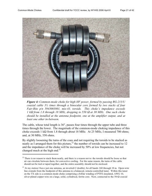
<strong>Common</strong>-<strong>Mode</strong> <strong>Chokes</strong> Confidential draft for YCCC review, <strong>by</strong> <strong>W1HIS</strong> 2006 April 6 Page 20 of 42I put two such chokes in this cable. I put a string of three such chokes in the telephonelinecable connected to this modem, 18 and I put a string of binocular-core chokes in the10Base-T Ethernet cable also connected to this modem. The telephone cable, whichextends through my house and outside, passing under one end of my HF antenna on itsway to the street, has several more chokes along the way. The wall-wart plugs into amultiple-outlet box with a computer and other peripherals. Additional common-modechokes and an L-C, difference-mode, filter are in the three-conductor cable feeding 120-VAC power to this box. 19 The Ethernet cable goes to the computer and is short. Everyother cable connecting this computer to the world beyond (e.g., the telephone cable to itsPOTS modem and the telephone cables to its ISDN modem) also contains multiplechokes, at intervals.The impedance that I measured for a single toroidal choke like the one in Figure 3, buthaving 14 turns of 2 × AWG 20 zip cord, was greater than 1 kΩ from 1.1 MHz through26 MHz, but dropped to 340 Ω at 30 MHz.6.4. Thick cable (including coax for high RF power)For thicker cables of up to 0.5" diameter, e.g., RG-213/U coax and 3 × AWG 14, 60-Hzpowercords, it is feasible to string enough 2631102002 beads on a straight cable to makea good choke. A string of 22 of these beads has >1 kΩ impedance from 1.8 MHz throughat least 20 MHz and probably well beyond 30 MHz. 20 For sufficient choking impedanceyou should string more beads on the cable; e.g., 110 beads would yield >5 kΩ from 1.8 toat least 20 MHz 21 and would cost about $110.A choke having about the same common-mode choking impedance and power-handlingcapability in transmission-line mode as twenty-two #2631102002 beads on RG-213/U,but less vulnerable to heating <strong>by</strong> common-mode current, can be made <strong>by</strong> stacking Fair-Rite p/n 5943003801, mix-43 toroids to form a pair of “binocular” tubes each 2.400" o.d.,1.400" i.d., and 2.0" long, and threading RG-213/U through this core three and one-halftimes as shown in Figure 4. (This may be done with PL-259 connectors already attachedas shown.)18 See Figure 15 in Appendix 6.19 See Figure 10 in Appendix 5.20 As discussed in Appendix 1, I am not confident of my ability to measure high impedances (with magnitudesexceeding about 500 Ω) at high HF frequencies (exceeding about 20 MHz). It is especially difficultto measure such impedances meaningfully when the size of the device being measured is greater than afew inches. In the latter case, a two-plane transmission-line measurement should be made, not a twoterminal(single-plane) measurement. I am not presently equipped for two-plane measurements. However,one may extrapolate from measurements of a short string of beads. For example, the magnitude ofthe impedance of a 2" long <strong>by</strong> 1" wide “hairpin” of cable loaded with just two 2631102002 beads, one oneach leg, as measured <strong>by</strong> my Autek VA-1 bridge, is 100 Ω at 1.8 MHz, 300 Ω at 20 MHz, and 250 Ω at30 MHz. At this rate, 22 beads provide 2.8 kΩ at 30 MHz. The most excellent aspect of a longstring-of-beads choke is that (if it is straight, not coiled) one end is far from the other; so itsperformance is not limited <strong>by</strong> capacitance between its ends.21 Compare the WØIYH choke described in §5. Note that RG-213/U has half the loss of RG-303 and safelyhandles more RF power.
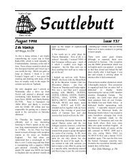
<strong>Common</strong>-<strong>Mode</strong> <strong>Chokes</strong> Confidential draft for YCCC review, <strong>by</strong> <strong>W1HIS</strong> 2006 April 6 Page 21 of 42Figure 4: <strong>Common</strong>-mode choke for high HF power, formed <strong>by</strong> passing RG-213/Ucoaxial cable 3½ times through a binocular core formed <strong>by</strong> two stacks of fourFair-Rite p/n 5943003801, mix-43, toroids. This choke’s impedance exceeds1 kΩ from 1.8 through 18 MHz, dropping to 550 Ω at 30 MHz. One such chokeshould be installed at the antenna feedpoint, one at the amplifier output, and atleast one other in-between.The cable, whose total length is 36", passes four times through the upper tube and threetimes through the lower. The magnitude of the common-mode choking impedance of thischoke exceeds 1 kΩ from 1.8 through about 18 MHz. At 25 MHz, I measured 700 ohms;and, at 30 MHz, 550 ohms.By slightly loosening the turns of the coax and not requiring the toroids to be stacked asneatly as I arranged them for this picture, 22 the number of toroids can be increased to 12and the impedance of the choke will be increased <strong>by</strong> 50% at low frequencies, but notchanged much at the high end. 2322 There is no reason to stack them neatly, and there is a reason not to: the toroids should be loose so thatair can circulate between them, for convective cooling. For the same reason, the turns of the cableshould not be tied or taped together, and the entire assembly should not be enclosed.23 At my station I have just one antenna, an inverted-U doublet, for all bands 160 through 10 m. Open-wireline extends from the feedpoint of this antenna to a balanced, remote-controlled tuner. Within this tuneron the TX side is a common-mode choke comprising a bifilar winding of PTFE-insulated, AWG 10,silver-plated copper wire on a large, solid, cylindrical, ferrite core. Next, connected to the 50-Ω coaxial