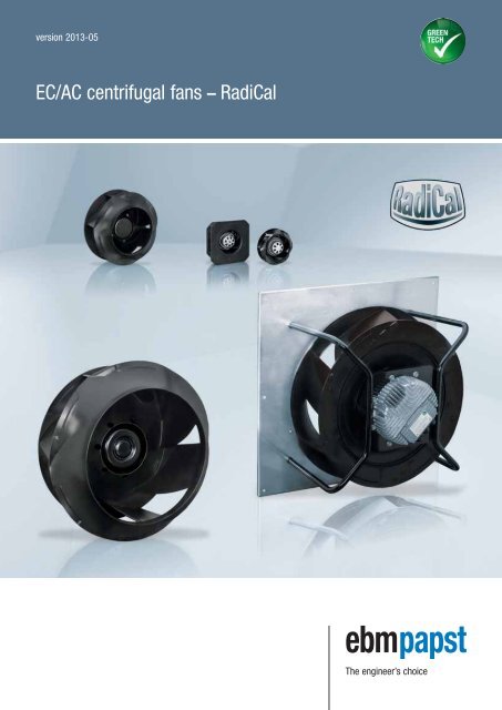
EC/AC centrifugal fans RadiCal
RadiCal EC/AC centrifugal fans (version 2013-05) [PDF] - ebm-papst
RadiCal EC/AC centrifugal fans (version 2013-05) [PDF] - ebm-papst
- No tags were found...

Create successful ePaper yourself
Turn your PDF publications into a flip-book with our unique Google optimized e-Paper software.
version 2013-05<strong>EC</strong>/<strong>AC</strong> <strong>centrifugal</strong> <strong>fans</strong> – <strong>RadiCal</strong>The engineer’s choice
<strong>EC</strong>/<strong>AC</strong> <strong>centrifugal</strong> <strong>fans</strong> – <strong>RadiCal</strong>Impellers made of high-tech compound material with optimised flow control,combined with proven single- or 3-phase asynchronous motors orhighly efficient GreenTech <strong>EC</strong> motors: these are the outstanding featuresof the new generation of backward-curved <strong>centrifugal</strong> <strong>fans</strong> for operationwithout scroll housing. That's <strong>RadiCal</strong>!The impellers in sizes 133 to 630mm are made of a single-piece specialcompound material which allows for high rotational speed, and thus forthe high power density of the fan. The impeller styling has been optimisedusing complex simulation models adjusted to perfection by checkingagainst prototypes. The result is an optimal, low-loss flow of air throughthe impeller and so there are no longer any drastic cross-sectional changes,a well-known source of losses in the impeller. A uniform flow profilewithout separations also means fewer noise sources and thus betteracoustics. That's <strong>RadiCal</strong>, too!The new motor in GreenTech <strong>EC</strong> technology with integrated control electronicsis designed in such as way as to make the <strong>RadiCal</strong> <strong>fans</strong> in sizes190 up to 250mm have the same mounting dimensions as the combinationof the same impeller with an asynchronous motor. In addition, thespecified <strong>EC</strong> <strong>centrifugal</strong> fan achieves significantly higher air performancethan the <strong>AC</strong> variant with identical dimensions. The small GreenTech <strong>EC</strong><strong>fans</strong> are available in two different control configurations: one with twofixed speed stages and another with the familiar continuous control optionvia a combined 0-10V/PWM control input. Sizes exceeding 250mm can becontrolled by a 0-10V/PWM input signal or monitored respectively controlledvia RS485 serial connection, using the MODBUS-RTU protocol.This opens up entirely new possibilities for applications in ventilation andair-conditioning and beyond. For example, ebm-papst <strong>AC</strong> <strong>fans</strong> can now bereplaced by the latest <strong>fans</strong> in GreenTech <strong>EC</strong> technology without anyexpensive modification.Advantages at a glance:– High efficiency with improved impeller technology and new <strong>EC</strong> motors– Perfectly matching components (controller/motor/impeller)– Extremely quietly running with optimised air flow through the impeller– Significantly reduced tonal noise– Unrivalled compactness– Mechanical compatibility of <strong>AC</strong> and <strong>EC</strong> <strong>fans</strong>– <strong>EC</strong> <strong>fans</strong> with 2 speeds or continuous control– High power density– Robust design and maintenance-free operation– Easy initial set-up– ErP* compliant (see individual designation)*ErP: Energy-related Products directive – defined minimum requirementsfor <strong>fans</strong> in accordance with the EcoDesign directive for <strong>fans</strong> with adrive output of 125 W and above.2
Table of contents<strong>EC</strong>/<strong>AC</strong> <strong>centrifugal</strong> <strong>fans</strong> - <strong>RadiCal</strong> 2GreenTech: The Green Company 4<strong>EC</strong> <strong>centrifugal</strong> <strong>fans</strong> - <strong>RadiCal</strong> Ø 133-630 7<strong>AC</strong> <strong>centrifugal</strong> <strong>fans</strong> - <strong>RadiCal</strong> Ø 133-630 101Accessories 158Electrical connections 163Technical parameters & scope 172ebm-papst representatives & subsidiaries 1763
Sustainability is at the centre of ourthoughts and actions. Out of conviction!PhilosophyApplicationDevelopmentProductionEco-friendliness and sustainability have always been at the core ofour thoughts and actions. For decades, we have worked accordingto the simple but strict creed of our co-founder Gerhard Sturm:“Each new product we develop has to be better than the last one interms of economy and ecology.” GreenTech is the ultimate expressionof our corporate philosophy.AwardsGreenTech is pro-active development.Even in the design phase, the materials and processes we use are optimisedfor the greatest possible eco-friendliness, energy balance and –wherever possible – recyclability. We continually improve the materialand performance of our products, as well as the flow and noise characteristics.At the same time, we significantly reduce energy consumption.Close co-operation with universities and scientific institutes and the professorshipwe endow in the area of power engineering and regenerativeenergies allows us to profit from the latest research findings in thesefields – and at the same time ensure highly qualified young academics.GreenTech is eco-friendly production.GreenTech also stands for maximum energy efficiency in our productionprocesses. There, the intelligent use of industrial waste heat and groundwatercooling, photovoltaics and, of course, our own cooling and ventilationtechnology are of the utmost importance. Our most modern plant,for instance, consumes 91% less energy than currently specified andrequired. In this way, our products contribute to protecting the environment,from their origin to their recyclable packaging.GreenTech is acknowledged and certified.Every step in our chain of production meets the stringent standards ofenvironmental specialists and the public. The Deutscher Nachhaltigkeitspreis2012 (German Sustainability Award 2012), where we were given theTop3-award in the category “Germany’s most sustainable strategy for thefuture (company group)” bears testimony to our commitment to sustainability,as does the DEKRA Award 2012 we received in the category “Umwelt –Herausforderung Energiewende / Environment – Challenge: Transition tomore sustainable energy systems”, to name only a few of a large numberof examples. The environmental advantage gained in the performance ofthe products developed from our GreenTech philosophy can also be measuredin the fulfillment of the most stringent energy and environmentalstandards. In many instances, our products are already well below thethresholds energy legislation will impose a few years from now – severaltimes over.Our customers profit from this every day.The heart of GreenTech is future-oriented <strong>EC</strong> technology from ebmpapst.The <strong>EC</strong> technology at the core of our most efficient motors and<strong>fans</strong> allows efficiency of up to 90%, saves energy at a very high level,significantly extends service life and makes our products maintenancefree.These values pay off not only for the environment, but every cent alsopays off for the user! All ebm-papst products – even those for whichGreenTech <strong>EC</strong> technology does not (yet) make sense from an applicationviewpoint – feature the greatest possible connection of economy andecology.4
<strong>EC</strong> <strong>centrifugal</strong> <strong>fans</strong> – <strong>RadiCal</strong>7
<strong>EC</strong> <strong>centrifugal</strong> <strong>fans</strong> – <strong>RadiCal</strong>backward curved, Ø 133– Material: Housing: PA plastic 6, fibreglass-reinforcedImpeller: PA plastic 6, fibreglass-reinforcedRotor: Thick layer passivatedElectronics enclosure: Die-cast aluminium– Number of blades: 7– Direction of rotation: Clockwise, seen on rotor– Type of protection: IP 54– Insulation class: "B"– Mounting position: Any– Condensate discharges: None, open rotor– Mode of operation: Continuous operation (S1)– Bearings: Maintenance-free ball bearingsNominal dataCurveNominalvoltage rangeFrequencySpeed/rpm (1)Max.input power (1)Max.current draw (1)Perm. amb. temp.Technical featuresand electricalconnectionTypeMotorV<strong>AC</strong> Hz rpm W A °C*3G 133 M3G 045-AIA1~ 200-240 50/60 3770 27 0,27 -25..+60p. 165 / H4)subject to alterations(1) Nominal data in operating point with maximum load and 230 V<strong>AC</strong>Curves:Speed-controlledp fs Pa0,2 0,4 0,6 0,8 1,0 1,2 1,4 1,6 in H 2O4003603202802402001601208040A40 20 40 60 80 100 120 140 160 cfm323 = ηmax.1AAAA1234nrpm3930380037703835P edW24262726IA0,230,260,270,25L W AdB(A)66636165q V40 80 120 160 200 240m 3 /hAir performance measured as per: ISO 5801, Installation category A, with ebm-papst inlet nozzle without protectionagainst accidental contact. Suction-side noise levels: L W A as per ISO 13347, L p A measured at 1 m distance to fan axis.The acoustic values given are only valid under the measurment conditions listed and may vary depending on the installationsituation. With any deviation to the standard setup, the specific values have to be checked and reviewed onceinstalled or fitted! For detailed information see page 172 ff.8
– Technical features: See electrical connections p. 165– EMC: Interference emission acc. to EN 61000-6-3Interference immunity acc. to EN 61000-6-2Harmonics acc. to EN 61000-3-2/3– Touch current: < 3,5 mA acc. to I<strong>EC</strong> 60990 (test circuit, illustration 4)– Cable exit: Variable– Protection class: I (if customer has provided connection for protective earth)– Product conforming to standards: EN 60335-1, CE– Approvals: VDE, UL, CSA, CCC, GOST are applied forMass of<strong>centrifugal</strong> fanMass of <strong>centrifugal</strong>module withsupport basketCentrifugal fankgCentrifugal modulew. support basketkgR3G 133-RA01 -030,5 K3G 133-RA01 -030,75Drawingsp. 10Inlet nozzlep. 158Guard grillep. 160Electr. connectionp. 1659
<strong>EC</strong> <strong>centrifugal</strong> <strong>fans</strong> – <strong>RadiCal</strong>backward curved, Ø 133, speed-controlledR3G 133-RA01-03 (Centrifugal fan)63±157.3Ø4.5 (4x)Accessory part:Inlet nozzle 09566-2-4013not included in the standardscope of deliveryDepth of screw max. 5 mmM4 (4x)4x90˚2Ø89Ø27Ø93±0.2Ø133Ø87Ø118Ø129Ø58±0.2450+2085±1048.511346Connection line AWG 20,3 x brass lead tips crimpedControl line AWG 22,4 x brass lead tips crimpedK3G 133-RA01-03 (Centrifugal module with support basket)Ø5 (4x)o165264645°o147±0.5Ø180±0.5Ø195±0.5Ø27Mountingdimensions:Ø210Ø195±0.5450+20685±1010
<strong>EC</strong> <strong>centrifugal</strong> <strong>fans</strong> – <strong>RadiCal</strong>backward curved, Ø 190– Material: Housing: PA plastic 6, fibreglass-reinforcedImpeller: PA plastic 6, fibreglass-reinforcedRotor: Thick layer passivatedElectronics enclosure: Die-cast aluminium– Number of blades: 7– Direction of rotation: Clockwise, seen on rotor– Type of protection: IP 54– Insulation class: "B"– Mounting position: Any– Condensate discharges: None, open rotor– Mode of operation: Continuous operation (S1)– Bearings: Maintenance-free ball bearingsNominal dataCurveNominalvoltage rangeFrequencySpeed/rpm (1)Max.input power (1)Max.current draw (1)Perm. amb. temp.Technical featuresand electricalconnectionType Motor V<strong>AC</strong> Hz rpm W A °C*3G 190 M3G 055-BD A 1~ 200-240 50/60 2710 57 0,43 -25..+60 p. 164 / H3)*3G 190 M3G 055-CF B 1~ 200-240 50/60 4120 169 1,35 -25..+60 p. 164 / H3)*3G 190 M3G 055-BI C 1~ 200-240 50/60 3200 83 0,75 -25..+60 p. 165 / H4)*3G 190 M3G 055-CF D 1~ 200-240 50/60 3640 115 1,10 -25..+60 p. 163 / H5)*3G 190 M3G 055-CF E 1~ 200-240 50/60 4120 169 1,35 -25..+60 p. 165 / H4)subject to alterations(1) Nominal data in operating point with maximum load and 230 V<strong>AC</strong>Curves:2 Speed stagesp fs Pa0,8 1,62,43,24,0 in H 2O1000800600400200AB8487435 10 100 200 300 4005006723637 = ηmax.251cfmAAAAAAAABBBBBBBB1234567812345678nrpm2880281527102780243523902325236044404235412041553720367536153650P edW495257543032353316016516916095105115110IA0,360,400,430,410,230,250,270,261,351,351,351,350,850,951,000,95L W AdB(A)69646267656059638175727477736972q V200 400 600 800m 3 /hAir performance measured as per: ISO 5801, Installation category A, with ebm-papst inlet nozzle without protectionagainst accidental contact. Suction-side noise levels: L W A as per ISO 13347, L p A measured at 1 m distance to fan axis.The acoustic values given are only valid under the measurment conditions listed and may vary depending on the installationsituation. With any deviation to the standard setup, the specific values have to be checked and reviewed onceinstalled or fitted! For detailed information see page 172 ff.12
– Technical features: See electrical connections p. 163 ff.– EMC: Interference emission acc. to EN 61000-6-3Interference immunity acc. to EN 61000-6-2Harmonics acc. to EN 61000-3-2/3– Touch current: < 3,5 mA acc. to I<strong>EC</strong> 60990 (test circuit, illustration 4)– Cable exit: Variable– Protection class: I (if customer has provided connection for protective earth)– Product conforming to standards: EN 60335-1, CE– Approvals: VDE, UL, CSA, CCC, GOST are applied forMass of<strong>centrifugal</strong> fanMass of <strong>centrifugal</strong>module withsupport basketCentrifugal fankgCentrifugal modulew. support basketkgR3G 190-RB01 -01 0,85 K3G 190-RB01 -01 1,40R3G 190-RD45 -01 1,36 K3G 190-RD45 -01 1,91R3G 190-RC05 -03 1,06 K3G 190-RC05 -03 1,61R3G 190-RG19 -01 1,40 K3G 190-RG19 -01 1,60R3G 190-RD45 -03 1,36 K3G 190-RD45 -03 1,91Curves:Speed-controlledp fs Pa0,8 1,62,43,24,0 in H 2O1000800600400200CD4E441 10 100 200 300 400500q V200 400 600 800333223 = ηmax.21cfmm 3 /hCCCCDDDDEEEE123412341234nrpm343533353200330039803865364038404440423541204155P edW80838383115115115115160165169160IA0,690,730,750,741,101,101,101,101,351,351,351,35L W AdB(A)736866707874717681757274Air performance measured as per: ISO 5801, Installation category A, with ebm-papst inlet nozzle without protectionagainst accidental contact. Suction-side noise levels: L W A as per ISO 13347, L p A measured at 1 m distance to fan axis.The acoustic values given are only valid under the measurment conditions listed and may vary depending on the installationsituation. With any deviation to the standard setup, the specific values have to be checked and reviewed onceinstalled or fitted! For detailed information see page 172 ff.Drawingsp. 14 ff.Inlet nozzlep. 158Guard grillep. 160Electr. connectionp. 163 ff.13
<strong>EC</strong> <strong>centrifugal</strong> <strong>fans</strong> – <strong>RadiCal</strong>backward curved, Ø 190, 2 speed stages, 85 W - electronicsR3G 190-RB01-01 (Centrifugal fan)Ø4.5 (4x)Accessory part:Inlet nozzle 09576-2-4013not included in the standardscope of deliveryM4 (4x)Depth of screw max. 5 mm2Ø89Ø27Ø80Ø72Ø132.8±0.2Ø190Ø125.5Ø158Ø170450+2085±10662.568.5±12141.25Connection line AWG 20,4 x brass lead tips crimpedØ58±0.2K3G 190-RB01-01 (Centrifugal module with support basket)Ø5 (4x)o225 796o204±0.545°Ø265±0.5Ø244Ø265±0.5Mountingdimensions:6450+2085±1014
<strong>EC</strong> <strong>centrifugal</strong> <strong>fans</strong> – <strong>RadiCal</strong>backward curved, Ø 190, 2 speed stages, 170 W - electronicsR3G 190-RD45-01 (Centrifugal fan)Ø4.5 (4x)Accessory part:Inlet nozzle 09576-2-4013not included in the standardscope of deliveryM4(4x)Depth of screw max. 5 mmDepth of screw max. 10 mmM6(4x)5Ø101Ø75Ø72Ø132.8±0.2Ø190Ø125.5Ø158Ø170450+2085±10662.588±1141.25Ø58±0.2Ø90±0.22Connection line AWG 20,4 x brass lead tips crimpedK3G 190-RD45-01 (Centrifugal module with support basket)Ø5 (4x)o225796o204±0.545°Ø265±0.5Ø244Ø265±0.5Mountingdimensions:6450+2085±1015
<strong>EC</strong> <strong>centrifugal</strong> <strong>fans</strong> – <strong>RadiCal</strong>backward curved, Ø 190, speed-controlled, 85 W - electronicsR3G 190-RC05-03 (Centrifugal fan)Ø4.5 (4x)Accessory part:Inlet nozzle 09576-2-4013not included in the standardscope of deliveryM4 (4x)Depth of screw max. 5 mm2Ø89Ø27Ø80Ø72Ø132.8±0.2Ø190Ø125.5Ø158Ø170450+2085±10662.568.5±12141.25Ø58±0.2Connection line AWG 20,3 x brass lead tips crimpedControl line AWG 22,4 x brass lead tips crimpedK3G 190-RC05-03 (Centrifugal module with support basket)Ø5 (4x)o225 796o204±0.545°Ø265±0.5Ø244Ø265±0.5Mountingdimensions:6450+2085±1016
R10<strong>EC</strong> <strong>centrifugal</strong> <strong>fans</strong> – <strong>RadiCal</strong>backward curved, Ø 190, speed-controlled, 115 W - electronicsR3G 190-RG19-01 (Centrifugal fan)Accessory part:Inlet nozzle 09576-2-4013not included in the standard scopeof deliveryØ4.5 (4x)M4 (4x)Depth of screw max. 6 mmM4 (4x)Depth of screw max. 6 mmØ115max.Ø95Ø132.8Ø190Ø125.5Ø158Ø170450 +2085 ±1061.2562.51469±1952K3G 190-RG19-01 (Centrifugal module with support basket)58105±0.2±0.2Connection line PVC 3G 0.5 mm 2 ,3 x brass lead tips crimpedConnection line PVC 4X 0.25 mm 2 ,4 x brass lead tips crimped107.522585.5Ø5 (4x) 6204±0.545°Ø266±0.5Ø244±0.5Ø266 ±0.5Mountingdimensions:450+2085±10617
<strong>EC</strong> <strong>centrifugal</strong> <strong>fans</strong> – <strong>RadiCal</strong>backward curved, Ø 190, speed-controlled, 170 W - electronicsR3G 190-RD45-03 (Centrifugal fan)Ø4.5 (4x)Accessory part:Inlet nozzle 09576-2-4013not included in the standardscope of deliveryM4(4x)Depth of screw max. 5 mmDepth of screw max. 10 mmM6(4x)5Ø101Ø75Ø72Ø132.8±0.2Ø190Ø125.5Ø158Ø170450+2085±10662.588±1141.25Ø58±0.2Ø90±0.22Control line AWG 22,4 x brass lead tips crimpedConnection line AWG 20,3 x brass lead tips crimpedK3G 190-RD45-03 (Centrifugal module with support basket)Ø5 (4x)o225796o204±0.545°Ø265±0.5Ø244Ø265±0.5Mountingdimensions:6450+2085±1018
<strong>EC</strong> <strong>centrifugal</strong> <strong>fans</strong> – <strong>RadiCal</strong>backward curved, Ø 220– Material: Housing: PA plastic 6, fibreglass-reinforcedImpeller: PA plastic 6, fibreglass-reinforcedRotor: Thick layer passivatedElectronics enclosure: Die-cast aluminium– Number of blades: 7– Direction of rotation: Clockwise, seen on rotor– Type of protection: IP 54– Insulation class: "B"– Mounting position: Any– Condensate discharges: None, open rotor– Mode of operation: Continuous operation (S1)– Bearings: Maintenance-free ball bearingsNominal dataCurveNominalvoltage rangeFrequencySpeed/rpm (1)Max.input power (1)Max.current draw (1)Perm. amb. temp.Technical featuresand electricalconnectionType Motor V<strong>AC</strong> Hz rpm W A °C*3G 220 M3G 055-BI A 1~ 200-240 50/60 2580 85 0,70 -25..+60 p. 164 / H3)*3G 220 M3G 055-CF B 1~ 200-240 50/60 3230 168 1,40 -25..+50 p. 164 / H3)*3G 220 M3G 055-BI C 1~ 200-240 50/60 2580 85 0,70 -25..+60 p. 165 / H4)*3G 220 M3G 055-CF D 1~ 200-240 50/60 2790 115 1,10 -25..+50 p. 163 / H5)*3G 220 M3G 055-CF E 1~ 200-240 50/60 3230 168 1,40 -25..+50 p. 165 / H4)subject to alterations(1) Nominal data in operating point with maximum load and 230 V<strong>AC</strong>Curves:2 Speed stagesp fs Pa0,8 1,62,43,2in H 2O800600400200q VBA8748645 10 100 200 300 400 500 600 7003200 400 600 800 1000 1200 m 3 /h732637 = ηmax.251cfmAAAAAAAABBBBBBBB1234567812345678nrpm2765270025802630150514851470148535403370323033103000295529002930P edW7985858516161717168168168168100110120115IA0,670,690,700,700,180,200,210,191,401,401,401,400,850,951,000,97L W AdB(A)71676566575451527773707274706870Air performance measured as per: ISO 5801, Installation category A, with ebm-papst inlet nozzle without protectionagainst accidental contact. Suction-side noise levels: L W A as per ISO 13347, L p A measured at 1 m distance to fan axis.The acoustic values given are only valid under the measurment conditions listed and may vary depending on the installationsituation. With any deviation to the standard setup, the specific values have to be checked and reviewed onceinstalled or fitted! For detailed information see page 172 ff.20
– Technical features: See electrical connections p. 163 ff.– EMC: Interference emission acc. to EN 61000-6-3Interference immunity acc. to EN 61000-6-2Harmonics acc. to EN 61000-3-2/3– Touch current: < 3,5 mA acc. to I<strong>EC</strong> 60990 (test circuit, illustration 4)– Cable exit: Variable– Protection class: I (if customer has provided connection for protective earth)– Product conforming to standards: EN 60335-1, CE– Approvals: VDE, UL, CSA, CCC, GOST are applied forMass of<strong>centrifugal</strong> fanMass of <strong>centrifugal</strong>module withsupport basketCentrifugal fankgCentrifugal modulew. support basketkgR3G 220-RC05 -01 1,13 K3G 220-RC05 -01 2,03R3G 220-RD53 -01 1,53 K3G 220-RD53 -01 2,43R3G 220-RC05 -03 1,20 K3G 220-RC05 -03 2,10R3G 220-RG19 -01 1,40 K3G 220-RG19 -01 2,00R3G 220-RD53 -03 1,53 K3G 220-RD53 -03 2,43Curves:Speed-controlledp fs Pa0,8 1,62,43,2in H 2O800600400200q VCD44E41 10 100 200 300 400 500 600 70033200 400 600 800 1000 1200 m 3 /h3223 = ηmax.21cfmCCCCDDDDEEEE123412341234nrpm276527002580263530852935279029403540337032303310P edW79858585115115115115168168168168IA0,670,690,700,701,101,101,101,101,401,401,401,40L W AdB(A)716765667469667077737072Air performance measured as per: ISO 5801, Installation category A, with ebm-papst inlet nozzle without protectionagainst accidental contact. Suction-side noise levels: L W A as per ISO 13347, L p A measured at 1 m distance to fan axis.The acoustic values given are only valid under the measurment conditions listed and may vary depending on the installationsituation. With any deviation to the standard setup, the specific values have to be checked and reviewed onceinstalled or fitted! For detailed information see page 172 ff.Drawingsp. 22 ff.Inlet nozzlep. 158Guard grillep. 160Electr. connectionp. 163 ff.21
<strong>EC</strong> <strong>centrifugal</strong> <strong>fans</strong> – <strong>RadiCal</strong>backward curved, Ø 220, 2 speed stages, 85 W - electronicsR3G 220-RC05-01 (Centrifugal fan)Ø5.5 (6x)Accessory part:Inlet nozzle 09609-2-4013not included in the standardscope of deliveryM4 (4x)Depth of screw max. 5 mm2Ø89Ø27Ø80Ø72Ø161±0.2Ø220Ø155Ø242Ø252450+2085±10663.771±12210.8Connection line AWG 20,4 x brass lead tips crimpedØ58±0.2K3G 220-RC05-01 (Centrifugal module with support basket)Ø5 (4x)o270 927o247.5±0.545°Ø305±0.5Ø294.5Ø305±0.5Mountingdimensions:6450+2085±1022
<strong>EC</strong> <strong>centrifugal</strong> <strong>fans</strong> – <strong>RadiCal</strong>backward curved, Ø 220, 2 speed stages, 170 W - electronicsR3G 220-RD53-01 (Centrifugal fan)Ø5.5 (6x)Accessory part:Inlet nozzle 09609-2-4013not included in the standardscope of deliveryM4(4x)Depth of screw max. 5 mmDepth of screw max. 10 mmM6(4x)5Ø101Ø75Ø72Ø161±0.2Ø220Ø155Ø242Ø252450+2085±10663.790±1210.8Ø58±0.2Ø90±0.22Connection line AWG 20,4 x brass lead tips crimpedK3G 220-RD53-01 (Centrifugal module with support basket)Ø5 (4x)o270927o247.5±0.545°Ø305±0.5Ø294.5Ø305±0.5Mountingdimensions:6450+2085±1023
<strong>EC</strong> <strong>centrifugal</strong> <strong>fans</strong> – <strong>RadiCal</strong>backward curved, Ø 220, speed-controlled, 85 W - electronicsR3G 220-RC05-03 (Centrifugal fan)Ø5.5 (6x)Accessory part:Inlet nozzle 09609-2-4013not included in the standardscope of deliveryM4 (4x)Depth of screw max. 5 mm2Ø89Ø27Ø80Ø72Ø161±0.2Ø220Ø155Ø242Ø252450+2085±10663.771±12210.8Ø58±0.2Connection line AWG 20,3 x brass lead tips crimpedControl line AWG 22,4 x brass lead tips crimpedK3G 220-RC05-03 (Centrifugal module with support basket)Ø5 (4x)o270 927o247.5±0.545°Ø305±0.5Ø294.5Ø305±0.5Mountingdimensions:6450+2085±1024
±10<strong>EC</strong> <strong>centrifugal</strong> <strong>fans</strong> – <strong>RadiCal</strong>backward curved, Ø 220, speed-controlled, 115 W - electronicsR3G 220-RG19-01 (Centrifugal fan)95 ±171±1Ø5.5 (6x)Accessory part:Inlet nozzle 09609-2-4013not included in the standardscope of deliveryDepth of screw max. 6 mmM4 (4x)Depth of screw max. 6 mmM4 (4x)R21.8Ø115max.Ø95Ø161Ø220Ø155Ø242Ø25245085+2063.7212K3G 220-RG19-01 (Centrifugal module with support basket)0.8Ø58Ø105±0.2±0.2Connection line PVC 3G 0.5 mm 2 ,3 x brass lead tips crimped6Connection line PVC 4X 0.25 mm 2 ,4 x brass lead tips crimped11627099Ø5 (4x) 7247.5±0.545°Ø305±0.5Ø294.5±0.5Ø305 ±0.5Mountingdimensions:450+2085±10625
<strong>EC</strong> <strong>centrifugal</strong> <strong>fans</strong> – <strong>RadiCal</strong>backward curved, Ø 220, speed-controlled, 170 W - electronicsR3G 220-RD53-03 (Centrifugal fan)Ø5.5 (6x)Accessory part:Inlet nozzle 09609-2-4013not included in the standardscope of deliveryM4(4x)Depth of screw max. 5 mmDepth of screw max. 10 mmM6(4x)5Ø101Ø75Ø72Ø161±0.2Ø220Ø155Ø242Ø252450+2085±10663.790±1210.8Ø58±0.2Ø90±0.22Control line AWG 22,4 x brass lead tips crimpedConnection line AWG 20,3 x brass lead tips crimpedK3G 220-RD53-03 (Centrifugal module with support basket)Ø5 (4x)o270927o247.5±0.545°Ø305±0.5Ø294.5Ø305±0.5Mountingdimensions:6450+2085±1026
<strong>EC</strong> <strong>centrifugal</strong> <strong>fans</strong> – <strong>RadiCal</strong>backward curved, Ø 225– Material: Housing: PA plastic 6, fibreglass-reinforcedImpeller: PA plastic 6, fibreglass-reinforcedRotor: Thick layer passivatedElectronics enclosure: Die-cast aluminium– Number of blades: 7– Direction of rotation: Clockwise, seen on rotor– Type of protection: IP 54– Insulation class: "B"– Mounting position: Any– Condensate discharges: None, open rotor– Mode of operation: Continuous operation (S1)– Bearings: Maintenance-free ball bearingsNominal dataCurveNominalvoltage rangeFrequencySpeed/rpm (1)Max.input power (1)Max.current draw (1)Perm. amb. temp.Technical featuresand electricalconnectionType Motor V<strong>AC</strong> Hz rpm W A °C*3G 225 M3G 055-CF A 1~ 200-240 50/60 2200 82 0,70 -25..+60*3G 225 M3G 055-DF B 1~ 200-240 50/60 2860 170 1,40 -25..+60*3G 225 M3G 055-CF C 1~ 200-240 50/60 2200 82 0,70 -25..+60*3G 225 M3G 055-CF D 1~ 200-240 50/60 2440 115 1,10 -25..+40p. 164 / H3)p. 164 / H3)p. 165 / H4)p. 163 / H5)*3G 225 M3G 055-DF E 1~ 200-240 50/60 2860 170 1,40 -25..+60 p. 165 / H4)subject to alterations(1) Nominal data in operating point with maximum load and 230 V<strong>AC</strong>Curves:2 Speed stagesp fs Pa0,4 0,8 1,2 1,6 2,0 2,4 2,8 in H 2O72064056048040032024016080q V848A41 50 100 200 300 400 500 600 70037 26B200 400 600 800 1000 1200753637 = ηmax.21cfmm 3 /hAAAAAAAABBBBBBBB1234567812345678nrpm2290217022002225164015851590163030302910286029702550249524902525P edW70778273273131281501651701559110410597IA0,620,660,700,630,280,310,320,291,251,401,401,350,830,940,930,89L W AdB(A)69656066615853587874687374706569Air performance measured as per: ISO 5801, Installation category A, with ebm-papst inlet nozzle without protectionagainst accidental contact. Suction-side noise levels: L W A as per ISO 13347, L p A measured at 1 m distance to fan axis.The acoustic values given are only valid under the measurment conditions listed and may vary depending on the installationsituation. With any deviation to the standard setup, the specific values have to be checked and reviewed onceinstalled or fitted! For detailed information see page 172 ff.28
– Technical features: See electrical connections p. 163 ff.– EMC: Interference emission acc. to EN 61000-6-3Interference immunity acc. to EN 61000-6-2Harmonics acc. to EN 61000-3-2/3– Touch current: < 3,5 mA acc. to I<strong>EC</strong> 60990 (test circuit, illustration 4)– Cable exit: Variable– Protection class: I (if customer has provided connection for protective earth)– Product conforming to standards: EN 60335-1, CE– Approvals: VDE, UL, CSA, CCC, GOST are applied forMass of<strong>centrifugal</strong> fanMass of <strong>centrifugal</strong>module withsupport basketCentrifugal fankgCentrifugal modulew. support basketkgR3G 225-RD05 -01 1,40 K3G 225-RD05 -01 2,00R3G 225-RE07 -01 1,60 K3G 225-RE07 -01 2,20R3G 225-RD05 -03 1,40 K3G 225-RD05 -03 2,00R3G 225-RH19 -01 1,50 K3G 225-RH19 -01 2,10R3G 225-RE07 -03 1,60 K3G 225-RE07 -03 2,20Curves:Speed-controlledp fs Pa0,4 0,8 1,2 1,6 2,0 2,4 2,8 in H 2O72064056048040032024016080CDE4441 10 100 200 300 400 500 600 700332323 = ηmax.21cfmCCCCDDDDEEEE123412341234nrpm229021702200222526852445244026403030291028602970P edW70778273115115115115150165170155IA0,620,660,700,631,101,101,101,101,251,401,401,35L W AdB(A)696560667367637178746873q V200 400 600 800 1000 1200m 3 /hAir performance measured as per: ISO 5801, Installation category A, with ebm-papst inlet nozzle without protectionagainst accidental contact. Suction-side noise levels: L W A as per ISO 13347, L p A measured at 1 m distance to fan axis.The acoustic values given are only valid under the measurment conditions listed and may vary depending on the installationsituation. With any deviation to the standard setup, the specific values have to be checked and reviewed onceinstalled or fitted! For detailed information see page 172 ff.Drawingsp. 30 ff.Inlet nozzlep. 158Guard grillep. 160Electr. connectionp. 163 ff.29
<strong>EC</strong> <strong>centrifugal</strong> <strong>fans</strong> – <strong>RadiCal</strong>backward curved, Ø 225, 2 speed stages, 85 W - electronicsR3G 225-RD05-01 (Centrifugal fan)Ø4.5 (4x)Accessory part:Inlet nozzle 96358-2-4013not included in the standardscope of deliveryM4 (4x)Depth of screw max. 5 mm2Ø89Ø27Ø80Ø72Ø153.5±0.2Ø225Ø146Ø210Ø223450+2085±10688.499±12281.5Connection line AWG 20,4 x brass lead tips crimpedØ58±0.2K3G 225-RD05-01 (Centrifugal module with support basket)Ø5 (4x)o270 1127o247.5±0.545°Ø305±0.5Ø294.5Ø305±0.5Mountingdimensions:6450+2085±1030
<strong>EC</strong> <strong>centrifugal</strong> <strong>fans</strong> – <strong>RadiCal</strong>backward curved, Ø 225, 2 speed stages, 170 W - electronicsR3G 225-RE07-01 (Centrifugal fan)Ø4.5 (4x)Accessory part:Inlet nozzle 96358-2-4013not included in the standardscope of deliveryM4(4x)Depth of screw max. 5 mmDepth of screw max. 10 mmM6(4x)5Ø101Ø75Ø72Ø153.5±0.2Ø225Ø146Ø210Ø223450+2085±10688.499±1281.5Ø58±0.2Ø90±0.22Connection line AWG 20,4 x brass lead tips crimpedK3G 225-RE07-01 (Centrifugal module with support basket)Ø5 (4x)o2701197o247.5±0.545°Ø305±0.5Ø294.5Ø305±0.5Mountingdimensions:6450+2085±1031
<strong>EC</strong> <strong>centrifugal</strong> <strong>fans</strong> – <strong>RadiCal</strong>backward curved, Ø 225, speed-controlled, 85 W - electronicsR3G 225-RD05-03 (Centrifugal fan)Ø4.5 (4x)Accessory part:Inlet nozzle 96358-2-4013not included in the standardscope of deliveryM4 (4x)Depth of screw max. 5 mm2Ø89Ø27Ø80Ø72Ø153.5±0.2Ø225Ø146Ø210Ø223450+2085±10688.499±12281.5Ø58±0.2Connection line AWG 20,3 x brass lead tips crimpedControl line AWG 22,4 x brass lead tips crimpedK3G 225-RD05-03 (Centrifugal module with support basket)Ø5 (4x)o270 1127o247.5±0.545°Ø305±0.5Ø294.5Ø305±0.5Mountingdimensions:6450+2085±1032
<strong>EC</strong> <strong>centrifugal</strong> <strong>fans</strong> – <strong>RadiCal</strong>backward curved, Ø 225, speed-controlled, 115 W - electronicsR3G 225-RH19-01 (Centrifugal fan)111±194±1Ø4.5 (4x)Accessory part:Inlet nozzle 96358-2-4013not included in the standardscope of deliveryM4 (4x)M4 (4x)Depth of screw max. 6 mmDepth of screw max. 6 mmR25Ø115max.Ø95Ø153.5Ø225Ø146Ø210Ø223450856+20±1088.4281.5Ø58Ø105±0.2±0.2K3G 225-RH19-01 (Centrifugal module with support basket)2Connection line PVC 3G 0.5 mm 2 ,3 x brass lead tips crimpedConnection line PVC 4X 0.25 mm 2 ,4 x brass lead tips crimped127.15270112Ø5 (4x) 7247.5±0.545°Ø305±0.5Ø294.5±0.5Ø305 ±0.5Mountingdimensions:450+2085±10633
<strong>EC</strong> <strong>centrifugal</strong> <strong>fans</strong> – <strong>RadiCal</strong>backward curved, Ø 225, speed-controlled, 170 W - electronicsR3G 225-RE07-03 (Centrifugal fan)Ø4.5 (4x)Accessory part:Inlet nozzle 96358-2-4013not included in the standardscope of deliveryM4(4x)Depth of screw max. 5 mmDepth of screw max. 10 mmM6(4x)5Ø101Ø75Ø72Ø153.5±0.2Ø225Ø146Ø210Ø223450+2085±10688.499±1281.5Ø58±0.2Ø90±0.22Control line AWG 22,4 x brass lead tips crimpedConnection line AWG 20,3 x brass lead tips crimpedK3G 225-RE07-03 (Centrifugal module with support basket)Ø5 (4x)o2701197o247.5±0.545°Ø305±0.5Ø294.5Ø305±0.5Mountingdimensions:6450+2085±1034
<strong>EC</strong> <strong>centrifugal</strong> <strong>fans</strong> – <strong>RadiCal</strong>backward curved, Ø 250– Material: Housing: PA plastic 6, fibreglass-reinforcedImpeller: PA plastic 6, fibreglass-reinforcedRotor: Thick layer passivatedElectronics enclosure: Die-cast aluminium– Number of blades: 7– Direction of rotation: Clockwise, seen on rotor– Type of protection: IP 54– Insulation class: "B"– Mounting position: Any– Condensate discharges: None, open rotor– Mode of operation: Continuous operation (S1)– Bearings: Maintenance-free ball bearingsNominal dataCurveNominalvoltage rangeFrequencySpeed/rpm (1)Max.input power (1)Max.current draw (1)Perm. amb. temp.Technical featuresand electricalconnectionType Motor V<strong>AC</strong> Hz rpm W A °C*3G 250 M3G 055-CF A 1~ 200-240 50/60 1955 80 0,70 -25..+60*3G 250 M3G 055-DF B 1~ 200-240 50/60 2510 170 1,40 -25..+60*3G 250 M3G 055-CF C 1~ 200-240 50/60 1955 80 0,70 -25..+60*3G 250 M3G 055-DF D 1~ 200-240 50/60 2510 170 1,40 -25..+60p. 164 / H3)p. 164 / H3)p. 165 / H4)p. 165 / H4)subject to alterations(1) Nominal data in operating point with maximum load and 230 V<strong>AC</strong>Curves:2 Speed stagesp fs Pa0,4 0,8 1,2 1,6 2,0 2,4in H 2O700600500400300200100q V8487A46B1 50 100 200 300 400 500 600 700 80035200 400 600 800 1000 1200 14007236327 = ηmax.1cfmm 3 /hAAAAAAAABBBBBBBB1234567812345678nrpm2050196519551990132512901290133026802565251026102330226522502285P edW708080782226262614517017016096110115110IA0,600,680,700,650,230,260,280,261,151,401,401,300,800,920,960,93L W AdB(A)69666166605753577671677372676468Air performance measured as per: ISO 5801, Installation category A, with ebm-papst inlet nozzle without protectionagainst accidental contact. Suction-side noise levels: L W A as per ISO 13347, L p A measured at 1 m distance to fan axis.The acoustic values given are only valid under the measurment conditions listed and may vary depending on the installationsituation. With any deviation to the standard setup, the specific values have to be checked and reviewed onceinstalled or fitted! For detailed information see page 172 ff.36
– Technical features: See electrical connections p. 164 ff.– EMC: Interference emission acc. to EN 61000-6-3Interference immunity acc. to EN 61000-6-2Harmonics acc. to EN 61000-3-2/3– Touch current: < 3,5 mA acc. to I<strong>EC</strong> 60990 (test circuit, illustration 4)– Cable exit: Variable– Protection class: I (if customer has provided connection for protective earth)– Product conforming to standards: EN 60335-1, CE– Approvals: VDE, UL, CSA, CCC, GOST are applied forMass of<strong>centrifugal</strong> fanMass of <strong>centrifugal</strong>module withsupport basketCentrifugal fankgCentrifugal modulew. support basketkgR3G 250-RD17 -01 1,50 K3G 250-RD17 -01 2,28R3G 250-RE07 -05 1,91 K3G 250-RE07 -05 2,69R3G 250-RD17 -03 1,50 K3G 250-RD17 -03 2,28R3G 250-RE07 -07 1,91 K3G 250-RE07 -07 2,69Curves:Speed-controlledp fs Pa0,4 0,8 1,2 1,6 2,0 2,4in H 2O700600500400300200100q VCD440 100 200 300 400 500 600 700 8003200 400 600 800 1000 1200 14002313 = ηmax.21cfmm 3 /hCCCCDDDD12341234nrpm20501965195519902680256525102610P edW70808078145170170160IA0,600,680,700,651,151,401,401,30L W AdB(A)6966616676716773Air performance measured as per: ISO 5801, Installation category A, with ebm-papst inlet nozzle without protectionagainst accidental contact. Suction-side noise levels: L W A as per ISO 13347, L p A measured at 1 m distance to fan axis.The acoustic values given are only valid under the measurment conditions listed and may vary depending on the installationsituation. With any deviation to the standard setup, the specific values have to be checked and reviewed onceinstalled or fitted! For detailed information see page 172 ff.Drawingsp. 38 ff.Inlet nozzlep. 158Guard grillep. 160Electr. connectionp. 164 ff.37
<strong>EC</strong> <strong>centrifugal</strong> <strong>fans</strong> – <strong>RadiCal</strong>backward curved, Ø 250, 2 speed stages, 85 W - electronicsR3G 250-RD17-01 (Centrifugal fan)Ø4.5 (4x)Accessory part:Inlet nozzle 96359-2-4013not included in the standardscope of deliveryM4 (4x)Depth of screw max. 5 mm2Ø89Ø27Ø80Ø72Ø172.5±0.2Ø250Ø164.5Ø240Ø255450+2085±1068599±12311.5Connection line AWG 20,4 x brass lead tips crimpedØ58±0.2K3G 250-RD17-01 (Centrifugal module with support basket)Ø5 (4x)o300 108.57o276±0.545°Ø340±0.5Ø322Ø340±0.5Mountingdimensions:6450+2085±1038
<strong>EC</strong> <strong>centrifugal</strong> <strong>fans</strong> – <strong>RadiCal</strong>backward curved, Ø 250, 2 speed stages, 170 W - electronicsR3G 250-RE07-05 (Centrifugal fan)Ø4.5 (4x)Accessory part:Inlet nozzle 96359-2-4013not included in the standardscope of deliveryM4(4x)Depth of screw max. 5 mmDepth of screw max. 10 mmM6(4x)5Ø101Ø75Ø72Ø172.5±0.2Ø250Ø164.5Ø240Ø255450+2085±1068599±1311.5Ø58±0.2Ø90±0.22Connection line AWG 20,4 x brass lead tips crimpedK3G 250-RE07-05 (Centrifugal module with support basket)Ø5 (4x)o300108.57o276±0.545°Ø340±0.5Ø322Ø340±0.5Mountingdimensions:6450+2085±1039
<strong>EC</strong> <strong>centrifugal</strong> <strong>fans</strong> – <strong>RadiCal</strong>backward curved, Ø 250, speed-controlled, 85 W - electronicsR3G 250-RD17-03 (Centrifugal fan)Ø4.5 (4x)Accessory part:Inlet nozzle 96359-2-4013not included in the standardscope of deliveryM4 (4x)Depth of screw max. 5 mm2Ø89Ø27Ø80Ø72Ø172.5±0.2Ø250Ø164.5Ø240Ø255450+2085±1068599±12311.5Ø58±0.2Connection line AWG 20,3 x brass lead tips crimpedControl line AWG 22,4 x brass lead tips crimpedK3G 250-RD17-03 (Centrifugal module with support basket)Ø5 (4x)o300 108.57o276±0.545°Ø340±0.5Ø322Ø340±0.5Mountingdimensions:6450+2085±1040
<strong>EC</strong> <strong>centrifugal</strong> <strong>fans</strong> – <strong>RadiCal</strong>backward curved, Ø 250, speed-controlled, 170 W - electronicsR3G 250-RE07-07 (Centrifugal fan)Ø4.5 (4x)Accessory part:Inlet nozzle 96359-2-4013not included in the standardscope of deliveryM4(4x)Depth of screw max. 5 mmDepth of screw max. 10 mmM6(4x)5Ø101Ø75Ø72Ø172.5±0.2Ø250Ø164.5Ø240Ø255450+2085±1068599±1311.5Ø58±0.2Ø90±0.22Control line AWG 22,4 x brass lead tips crimpedConnection line AWG 20,3 x brass lead tips crimpedK3G 250-RE07-07 (Centrifugal module with support basket)Ø5 (4x)o300108.57o276±0.545°Ø340±0.5Ø322Ø340±0.5Mountingdimensions:6450+2085±1041
<strong>EC</strong> <strong>centrifugal</strong> <strong>fans</strong> – <strong>RadiCal</strong>backward curved, Ø 250– Material: Support bracket: Steel, coated in blackSupport plate and inlet nozzle: Sheet steel, galvanisedImpeller: Plastic PARotor: Coated in blackElectronics enclosure: Die-cast aluminium– Number of blades: 7– Direction of rotation: Clockwise, seen on rotor– Type of protection: IP 54– Insulation class: "F"– Mounting position: Shaft horizontal or rotor om bottom, rotor on top on request– Condensate discharges: Rotor-side– Mode of operation: Continuous operation (S1)– Bearings: Maintenance-free ball bearingsNominal dataCurveNominalvoltage rangeFrequencySpeed/rpm (1)Max.input power (1)Max.current draw (1)Perm. amb. temp.Technical featuresand electricalconnectionType Motor V<strong>AC</strong> Hz rpm W A °C*3G 250 M3G 084-DF A 1~ 200-277 50/60 3740 500 2,20 -25..+60 p. 166 / P5)*3G 250 M3G 084-DF B 1~ 200-277 50/60 4250 750 3,30 -25..+60 p. 166 / P5)subject to alterations(1) Nominal data in operating point with maximum load and 230 V<strong>AC</strong>Curves:p fs Pa1400120010008006004002000,8 1,6 2,4 3,2 4,0 4,8 5,6 in H 2O0q V44BA31 1200 400 600 800 1000 1200 cfm400 800 1200 1600 2000 m 3 /h323 = ηmax.2AAAABBBB12341234nrpm41003870374038604250425042504250P edW500500500500585685750695IA2,202,202,202,202,603,003,303,10L W AdB(A)8983788490868284Air performance measured as per: ISO 5801, Installation category A, with ebm-papst inlet nozzle without protectionagainst accidental contact. Suction-side noise levels: L W A as per ISO 13347, L p A measured at 1 m distance to fan axis.The acoustic values given are only valid under the measurment conditions listed and may vary depending on the installationsituation. With any deviation to the standard setup, the specific values have to be checked and reviewed onceinstalled or fitted! For detailed information see page 172 ff.42
– Technical features: See electrical connections p. 166– EMC: Interference emission acc. to EN 61000-6-3Interference immunity acc. to EN 61000-6-2Harmonics acc. to EN 61000-3-2/3– Touch current: < 3,5 mA acc. to I<strong>EC</strong> 60990 (test circuit, illustration 4)– Cable exit: Variable– Protection class: I (if customer has provided connection for protective earth)– Product conforming to standards: EN 60335-1, CE– Approvals: VDE, UL, CSA, CCC, GOST are applied forMass of<strong>centrifugal</strong> fanMass of <strong>centrifugal</strong>module withsupport bracketCentrifugal fankgCentrifugal modulew. support bracketkgR3G 250-RR01 -H1 4,1 K3G 250-RR01 -H2 8,1R3G 250-RR02 -I1 4,4 K3G 250-RR02 -I2 8,5Drawingsp. 44 ff.Inlet nozzlep. 158 ff.Guard grillep. 160Electr. connectionp. 16643
R28<strong>EC</strong> <strong>centrifugal</strong> <strong>fans</strong> – <strong>RadiCal</strong>backward curved, Ø 250R3G 250-RR01-H1 (Centrifugal fan)Accessory part: Inlet nozzle 96359-2-4013 not included in the standard scope of delivery47.74x Ø4.5M6 (4x)Depth of screw max. 16 mmØ178Ø150 ±0.35Ø172 +0.3-0.5Ø250Ø164.5Ø240Ø25585106.5 ±1.821.531Ø164 ±0.35Connection line AWG 18,5 x crimped core-end sleeves600+200885 ±10Connection line AWG 22,5 x crimped core-end sleevesK3G 250-RR01-H2 (Centrifugal module with support bracket)Ø11 (4x)Ø250130.5178 ±3±22295350400Observe the correct mounting position!Install the support struts only as shown in the view!44
R28<strong>EC</strong> <strong>centrifugal</strong> <strong>fans</strong> – <strong>RadiCal</strong>backward curved, Ø 250R3G 250-RR02-I1 (Centrifugal fan)Accessory part: Inlet nozzle 96359-2-4013 not included in the standard scope of delivery64.14x Ø4.5M6 (4x)Depth of screw max. 16 mmØ200Ø169 ±0.35Ø172 +0.3-0.5Ø250Ø164.5Ø240Ø25585106.5 ±1.821.531Ø186 ±0.5Connection line AWG 18,5 x crimped core-end sleeves600+200885 ±10Connection line AWG 22,5 x crimped core-end sleevesK3G 250-RR02-I2 (Centrifugal module with support bracket)Ø11 (4x)Ø250130.5194.6 ±3±22295350400Observe the correct mounting position!Install the support struts only as shown in the view!45
<strong>EC</strong> <strong>centrifugal</strong> <strong>fans</strong> – <strong>RadiCal</strong>backward curved, Ø 280– Material: Support bracket: Steel, coated in blackSupport plate and inlet nozzle: Sheet steel, galvanisedImpeller: Plastic PPRotor: A Surface passivated, B C Coated in blackElectronics enclosure: Die-cast aluminium– Number of blades: 6– Direction of rotation: Clockwise, seen on rotor– Type of protection: IP 54– Insulation class: A "B", B C "F"– Mounting position: A any, B C Shaft horizontal or rotor om bottom, rotor on top on request– Condensate discharges: A None (open rotor), B C Rotor-side– Mode of operation: Continuous operation (S1)– Bearings: Maintenance-free ball bearingsNominal dataCurveNominalvoltage rangeFrequencySpeed/rpm (1)Max.input power (1)Max.current draw (1)Perm. amb. temp.Technical featuresand electricalconnectionType Motor V<strong>AC</strong> Hz rpm W A °C*3G 280 M3G 074-CF A 1~ 200-240 50/60 1910 168 1,40 -25..+60 p. 165 / H4)*3G 280 M3G 084-DF B 1~ 200-277 50/60 2700 500 2,20 -25..+60 p. 166 / P5)*3G 280 M3G 084-DF C 1~ 200-277 50/60 2900 660 2,90 -25..+60 p. 166 / P5)subject to alterations(1) Nominal data in operating point with maximum load and 230 V<strong>AC</strong>Curves:p fs Pa9008007006005004003002001000,4 0,8 1,2 1,6 2,0 2,4 2,8 3,2 3,6 in H 2O0q V<strong>AC</strong>B C42 = ηmax.3 = ηmax.4B33A4223211 1200 400 600 800 1000 1200 1400 1600 1800 cfm500 1000 1500 2000 2500 3000 m 3 /hAAAABBBBCCCC123412341234nrpm198019101775184028802800270028102900290029002900P edW150168165165460500500500490600660600IA1,051,401,301,302,002,202,202,202,202,702,902,70L W AdB(A)756964648580747886817679Air performance measured as per: ISO 5801, Installation category A, with ebm-papst inlet nozzle without protectionagainst accidental contact. Suction-side noise levels: L W A as per ISO 13347, L p A measured at 1 m distance to fan axis.The acoustic values given are only valid under the measurment conditions listed and may vary depending on the installationsituation. With any deviation to the standard setup, the specific values have to be checked and reviewed onceinstalled or fitted! For detailed information see page 172 ff.46
– Technical features: See electrical connections p. 165 ff.– EMC: Interference emission acc. to EN 61000-6-3Interference immunity acc. to EN 61000-6-2Harmonics acc. to EN 61000-3-2/3A On account of the installation conditions, ferritic damping in theconnection line may be required for the application.– Touch current: < 3,5 mA acc. to I<strong>EC</strong> 60990 (test circuit, illustration 4)– Cable exit: Variable– Protection class: I (if customer has provided connection for protective earth)– Product conforming to standards: A EN 60335-1, CE; B C EN 60335-1, EN 61800-5-1, CE– Approvals: A VDE, CURUS on request; B C VDE, UL, CSA, CCC, GOST are applied forMass of<strong>centrifugal</strong> fanMass of <strong>centrifugal</strong>module withsupport bracketCentrifugal fankgCentrifugal modulew. support bracketkgR3G 280-RB02 -03 2,7 K3G 280-RB02 -03 6,8R3G 280-RR03 -H1 4,3 K3G 280-RR03 -H2 8,4R3G 280-RR04 -I1 4,6 K3G 280-RR04 -I2 8,8Drawingsp. 48 ff.Inlet nozzlep. 158 ff.Guard grillep. 160Electr. connectionp. 165 ff.47
<strong>EC</strong> <strong>centrifugal</strong> <strong>fans</strong> – <strong>RadiCal</strong>backward curved, Ø 280R3G 280-RB02-03 (Centrifugal fan)1504x Ø4.5Accessory part:Inlet nozzle 28000-2-4013not included in the standardscope of deliveryM4(4x)M6(4x)Depth of screw max. 10 mm5R17R33R53Ø132.5Ø101Ø75Ø187.5Ø294Ø179.6Ø176.7Ø260Ø280600 +20127140 ±11.2546Ø90 ±0.2Ø125685±108Connection line AWG 20,3 x crimped core-end sleevesConnection line AWG 22,4 x crimped core-end sleevesK3G 280-RB02-03 (Centrifugal module with support bracket)Ø11(4x)856600+20Ø294177.5193.5 ±3±2.52298350400Observe the correct mounting position!Install the support struts only as shown in the view!48
<strong>EC</strong> <strong>centrifugal</strong> <strong>fans</strong> – <strong>RadiCal</strong>backward curved, Ø 280R3G 280-RR03-H1 (Centrifugal fan)Accessory part: Inlet nozzle 28000-2-4013 not included in the standard scope of delivery47.74x Ø4.5M6 (4x)Depth of screw max. 16 mmR17R33R53Ø178Ø150 ±0.35Ø187.5 ±0.3Ø294Ø179.6Ø176.7Ø260Ø280127142.75 ±1.81.2546Ø164 ±0.5Connection line AWG 18,5 x crimped core-end sleeves600+200885 ±108Connection line AWG 22,5 x crimped core-end sleevesK3G 280-RR03-H2 (Centrifugal module with support bracket)Ø11 (4x)Ø294175.5223.2 ±3±22295350400Observe the correct mounting position!Install the support struts only as shown in the view!49
<strong>EC</strong> <strong>centrifugal</strong> <strong>fans</strong> – <strong>RadiCal</strong>backward curved, Ø 280R3G 280-RR04-I1 (Centrifugal fan)Accessory part: Inlet nozzle 28000-2-4013 not included in the standard scope of delivery64.14x Ø4.5M6 (4x)Depth of screw max. 16 mmR17R33R53Ø200Ø169 ±0.35Ø187.5 ±0.3Ø294Ø179.6Ø176.7Ø260Ø280127142.75 ±1.881.2546Ø186 ±0.5Connection line AWG 18,5 x crimped core-end sleeves600+200885 ±10Connection line AWG 22,5 x crimped core-end sleevesK3G 280-RR04-I2 (Centrifugal module with support bracket)Ø11 (4x)Ø294175.5 ±2239.6 ±32295350400Observe the correct mounting position!Install the support struts only as shown in the view!50
<strong>EC</strong> <strong>centrifugal</strong> <strong>fans</strong> – <strong>RadiCal</strong>backward curved, Ø 310– Material: Support bracket: Steel, coated in blackSupport plate and inlet nozzle: Sheet steel, galvanisedImpeller: Plastic PPRotor: A Surface passivated, B C D Coated in blackElectronics enclosure: Die-cast aluminium– Number of blades: 6– Direction of rotation: Clockwise, seen on rotor– Type of protection: IP 54– Insulation class: A "B", B C D "F"– Mounting position: A any, B C D Shaft horizontal or rotor om bottom, rotor on top on request– Condensate discharges: A None (open rotor), B C D Rotor-side– Mode of operation: Continuous operation (S1)– Bearings: Maintenance-free ball bearingsNominal dataCurveNominalvoltage rangeFrequencySpeed/rpm (1)Max.input power (1)Max.current draw (1)Perm. amb. temp.Technical featuresand electricalconnectionType Motor V<strong>AC</strong> Hz rpm W A °C*3G 310 M3G 074-CF A 1~ 200-240 50/60 1525 150 1,20 -25..+60 p. 165 / H4)*3G 310 M3G 084-DF B 1~ 200-277 50/60 2360 500 2,20 -25..+60 p. 166 / P5)*3G 310 M3G 084-FA C 1~ 200-277 50/60 2640 740 3,25 -25..+60 p. 166 / P5)*3G 310 M3G 084-FA D 3~ 380-480 50/60 2700 790 1,25 -25..+60 p. 167 / P6)subject to alterations(1) Nominal data in operating point with maximum load and 230 or 400 V<strong>AC</strong>Curves:p fs Pa10009008007006005004003002001000,4 0,8 1,2 1,6 2,0 2,4 2,8 3,2 3,6 4,0 in H 2O0q VA4B3442DC33 311 1500 1000 1500 2000 cfm500 1000 1500 2000 2500 3000 3500 4000 m 3 /h223 = ηmax.AAAABBBBCCCCDDDD1234123412341234nrpm1600154515251545251024402360241027002700264027002700270027002700P edW115140150140430500500500550730740730560720790725IA0,951,101,201,151,902,202,202,202,453,203,253,200,891,151,251,15L W AdB(A)69655962817672778479757984797680Air performance measured as per: ISO 5801, Installation category A, with ebm-papst inlet nozzle without protectionagainst accidental contact. Suction-side noise levels: L W A as per ISO 13347, L p A measured at 1 m distance to fan axis.The acoustic values given are only valid under the measurment conditions listed and may vary depending on the installationsituation. With any deviation to the standard setup, the specific values have to be checked and reviewed onceinstalled or fitted! For detailed information see page 172 ff.52
– Technical features: See electrical connections p. 165 ff.– EMC: Interference emission acc. to EN 61000-6-3Interference immunity acc. to EN 61000-6-2Harmonics acc. to EN 61000-3-2/3A On account of the installation conditions, ferritic damping in theconnection line may be required for the application.– Touch current: < 3,5 mA acc. to I<strong>EC</strong> 60990 (test circuit, illustration 4)– Cable exit: Variable– Protection class: I (if customer has provided connection for protective earth)– Product conforming to standards: A EN 60335-1, CE; B C D EN 60335-1, EN 61800-5-1, CE– Approvals: A VDE, CURUS on request; B C D VDE, UL, CSA, CCC, GOST are applied forMass of<strong>centrifugal</strong> fanMass of <strong>centrifugal</strong>module withsupport bracketCentrifugal fankgCentrifugal modulew. support bracketkgR3G 310-RB01 -03 2,9 K3G 310-RB01 -03 7,5R3G 310-RR05 -H1 4,7 K3G 310-RR05 -H2 9,6R3G 310-RS01 -I1 5,7 K3G 310-RS01 -I2 10,7R3G 310-RS05 -J1 5,5 K3G 310-RS05 -J2 10,5Drawingsp. 54 ff.Inlet nozzlep. 158 ff.Guard grillep. 160Electr. connectionp. 165 ff.53
<strong>EC</strong> <strong>centrifugal</strong> <strong>fans</strong> – <strong>RadiCal</strong>backward curved, Ø 310R3G 310-RB01-03 (Centrifugal fan)163.4Ø4.5Accessory part:Inlet nozzle 31000-2-4013not included in the standardscope of deliveryM4(4x)M6(4x)Depth of screw max. 10 mm5Ø132.5Ø101Ø75Ø204Ø325.5Ø193.4Ø191.4Ø280Ø3004xR24.3R45.4R71.1600 +20141.5153 ±11.558.5Ø90Ø125±0.2685 ±10K3G 310-RB01-03 (Centrifugal module with support bracket)8Connection line AWG 20,3 x crimped core-end sleevesConnection line AWG 22,4 x crimped core-end sleevesØ6.4 (8x)Ø325.5200216±2.5±32320420440Observe the correct mounting position!Install the support struts only as shown in the view!54
<strong>EC</strong> <strong>centrifugal</strong> <strong>fans</strong> – <strong>RadiCal</strong>backward curved, Ø 310R3G 310-RR05-H1 (Centrifugal fan)Accessory part: Inlet nozzle 31000-2-4013 not included in the standard scope of delivery47.74x Ø4.5M6 (4x)Depth of screw max. 16 mmR24R71R45Ø178Ø150 ±0.35Ø204 ±0.4Ø325.5Ø193.4Ø191.5Ø280Ø300141.5153 ±281.558.5Ø164 ±0.35Connection line AWG 18,5 x crimped core-end sleeves60085 ±10+2008Connection line AWG 22,5 x crimped core-end sleevesK3G 310-RR05-H2 (Centrifugal module with support bracket)Ø6.4 (8x)Ø325.5200247.7±3±22320420440Observe the correct mounting position!Install the support struts only as shown in the view!55
<strong>EC</strong> <strong>centrifugal</strong> <strong>fans</strong> – <strong>RadiCal</strong>backward curved, Ø 310R3G 310-RS01-I1 (Centrifugal fan)Accessory part: Inlet nozzle 31000-2-4013 not included in the standard scope of deliveryDepth of screw max. 16 mm64.14x Ø4.5M6 (4x)R24R71R45Ø200Ø169 ±0.35Ø204 ±0.4Ø325.5Ø193.4Ø191.5Ø280Ø300141.5168 ±281.558.5Ø186 ±0.35Connection line AWG 18,5 x crimped core-end sleeves60085 ±10+2008Connection line AWG 22,5 x crimped core-end sleevesK3G 310-RS01-I2 (Centrifugal module with support bracket)Ø6.4 (8x)Ø325.5215279 ±3±22320420440Observe the correct mounting position!Install the support struts only as shown in the view!56
<strong>EC</strong> <strong>centrifugal</strong> <strong>fans</strong> – <strong>RadiCal</strong>backward curved, Ø 310R3G 310-RS05-J1 (Centrifugal fan)Accessory part: Inlet nozzle 31000-2-4013 not included in the standard scope of delivery64.14x Ø4.5M6 (4x)Depth of screw max. 16 mmR24R71R45Ø200Ø169 ±0.35Ø204 ±0.4Ø325.5Ø193.4Ø191.5Ø280Ø300141.5168 ±281.558.5Ø186 ±0.35Connection line AWG 18,6 x crimped core-end sleeves60085 ±10+2008Connection line AWG 22,5 x crimped core-end sleevesK3G 310-RS05-J2 (Centrifugal module with support bracket)Ø6.4 (8x)Ø325.5215279 ±3±22320420440Observe the correct mounting position!Install the support struts only as shown in the view!57
<strong>EC</strong> <strong>centrifugal</strong> <strong>fans</strong> – <strong>RadiCal</strong>backward curved, Ø 355– Material: Support bracket: Steel, coated in blackSupport plate and inlet nozzle: Sheet steel, galvanisedImpeller: Plastic PPRotor: A Surface passivated, B C D E Coated in blackElectronics enclosure: Die-cast aluminium– Number of blades: 6– Direction of rotation: Clockwise, seen on rotor– Type of protection: IP 54– Insulation class: A "B", B C D E "F"– Mounting position: A any, B C D E Shaft horizontal or rotor om bottom, rotor on top on request– Condensate discharges: A None (open rotor), B C D E Rotor-side– Mode of operation: Continuous operation (S1)– Bearings: Maintenance-free ball bearingsNominal dataCurveNominalvoltage rangeFrequencySpeed/rpm (1)Max.input power (1)Max.current draw (1)Perm. amb. temp.Technical featuresand electricalconnectionType Motor V<strong>AC</strong> Hz rpm W A °C*3G 355 M3G 074-CF A 1~ 200-240 50/60 1250 168 1,40 -25..+60 p. 165 / H4)*3G 355 M3G 084-DF B 1~ 200-277 50/60 1450 250 1,10 -25..+60 p. 166 / P5)*3G 355 M3G 084-FA C 1~ 200-277 50/60 1850 500 2,20 -25..+60 p. 166 / P5)*3G 355 M3G 084-GF D 1~ 200-277 50/60 2100 750 3,30 -25..+60 p. 166 / P5)*3G 355 M3G 112-EA E 3~ 380-480 50/60 2400 1140 1,80 -25..+60 p. 167 / P6)subject to alterations(1) Nominal data in operating point with maximum load and 230 or 400 V<strong>AC</strong>Curves:p fs Pa0,4 0,8 1,2 1,6 2,0 2,4 2,8 3,2 3,6 4,0 in H 2O1000900800700600500400300200100q V0ABC44DE3443423231 11 1 1500 1000 1500 2000 2500 3000 cfm1000 2000 3000 4000 5000 m 3 /h32223 = ηmax.Air performance measured as per: ISO 5801, Installation category A, with ebm-papst inlet nozzle without protectionagainst accidental contact. Suction-side noise levels: L W A as per ISO 13347, L p A measured at 1 m distance to fan axis.The acoustic values given are only valid under the measurment conditions listed and may vary depending on the installationsituation. With any deviation to the standard setup, the specific values have to be checked and reviewed onceinstalled or fitted! For detailed information see page 172 ff.AAAABBBBCCCCDDDDEEEE12341234123412341234nrpm14251305125012801660150514501525205019401850189022402165210021652400240024002400P edW165165168165250250250250455500500500630750750740790104011401090IA1,351,351,401,351,101,101,101,102,002,202,202,202,753,303,303,251,251,651,801,70L W AdB(A)716558607768636887787073878174779183767958
– Technical features: See electrical connections p. 165 ff.– EMC: Interference emission acc. to EN 61000-6-3Interference immunity acc. to EN 61000-6-2Harmonics acc. to EN 61000-3-2/3A On account of the installation conditions, ferritic damping in theconnection line may be required for the application.– Touch current: < 3,5 mA acc. to I<strong>EC</strong> 60990 (test circuit, illustration 4)– Cable exit: Variable– Protection class: I (if customer has provided connection for protective earth)– Product conforming to standards: A EN 60335-1, CE; B C D E EN 60335-1, EN 61800-5-1, CE– Approvals: A VDE, CURUS on request; B C D E VDE, UL, CSA, CCC, GOST are applied forMass of<strong>centrifugal</strong> fanMass of <strong>centrifugal</strong>module withsupport bracketCentrifugal fankgCentrifugal modulew. support bracketkgR3G 355-RB03 -03 3,7 K3G 355-RB03 -03 9,7R3G 355-RR06 -G1 5,0 K3G 355-RR06 -G2 10,8R3G 355-RS02 -H1 5,7 K3G 355-RS02 -H2 11,6R3G 355-RT01 -I1 6,9 K3G 355-RT01 -I2 14,9R3G 355-RJ75 -01 8,3 K3G 355-RJ75 -01 16,3Drawingsp. 60 ff.Inlet nozzlep. 158 ff.Guard grillep. 160Electr. connectionp. 165 ff.59
<strong>EC</strong> <strong>centrifugal</strong> <strong>fans</strong> – <strong>RadiCal</strong>backward curved, Ø 355R3G 355-RB03-03 (Centrifugal fan)181.44x Ø4.5Accessory part:Inlet nozzle 35500-2-4013not included in the standardscope of deliveryM4(4x)M6(4x)Depth of screw max. 10 mm5R43.5R69.5R22.5Ø132.5Ø101Ø75Ø237Ø372.5Ø227Ø223Ø325Ø350600 +20685161.5171 ±11.560Ø90Ø125±0.2±1010Connection line AWG 20,3 x crimped core-end sleevesConnection line AWG 22,4 x crimped core-end sleevesK3G 355-RB03-03 (Centrifugal module with support bracket)Ø6.4 (8x)Ø372.5226242±3±22351476496Observe the correct mounting position!Install the support struts only as shown in the view!60
R22.5<strong>EC</strong> <strong>centrifugal</strong> <strong>fans</strong> – <strong>RadiCal</strong>backward curved, Ø 355R3G 355-RR06-G1 (Centrifugal fan)47.7Accessory part: Inlet nozzle 35500-2-4013 not included in the standard scope of delivery4x Ø4.5Depth of screw max. 16 mmM6 (4x)R43.5R69.5Ø178Ø150 ±0.35Ø237 +1.5 -0.4Ø372.5Ø227Ø223Ø325Ø350161.75170 ±2101.560Ø164 ±0.35Connection line AWG 18,5 x crimped core-end sleeves60085 ±10+2008Connection line AWG 22,5 x crimped core-end sleevesK3G 355-RR06-G2 (Centrifugal module with support bracket)Ø6.4 (8x)Ø372.5217265 ±3±22351.5476496Observe the correct mounting position!Install the support struts only as shown in the view!61
R22.5<strong>EC</strong> <strong>centrifugal</strong> <strong>fans</strong> – <strong>RadiCal</strong>backward curved, Ø 355R3G 355-RS02-H1 (Centrifugal fan)Accessory part: Inlet nozzle 35500-2-4013 not included in the standard scope of delivery47.74x Ø4.5M6 (4x)Depth of screw max. 16 mmR43.5R69.5Ø178Ø150 ±0.35Ø237 +1.5 -0.4Ø372.5Ø227Ø223Ø325Ø350161.75183 ±2101.560Ø164 ±0.35Connection line AWG 18,5 x crimped core-end sleeves60085 ±10+2008Connection line AWG 22,5 x crimped core-end sleevesK3G 355-RS02-H2 (Centrifugal module with support bracket)Ø6.4 (8x)Ø372.5229277 ±3±22351.5476496Observe the correct mounting position!Install the support struts only as shown in the view!62
R22.5<strong>EC</strong> <strong>centrifugal</strong> <strong>fans</strong> – <strong>RadiCal</strong>backward curved, Ø 355R3G 355-RT01-I1 (Centrifugal fan)Accessory part: Inlet nozzle 35500-2-4013 not included in the standard scope of delivery64.14x Ø4.5M6 (4x)Depth of screw max. 16 mmR43.5R69.5Ø200Ø169 ±0.35161.75191 ±2+1.5-0.4Ø237Ø372.5Ø227Ø223101.560Ø325Ø350Ø186 ±0.5600Connection line AWG 18,5 x crimped core-end sleeves+200885 ±10Connection line AWG 22,5 x crimped core-end sleevesK3G 355-RT01-I2 (Centrifugal module with support bracket)Ø11 (4x)Ø372.5237301±3±215372450500Observe the correct mounting position!Install the support struts only as shown in the view!63
<strong>EC</strong> <strong>centrifugal</strong> <strong>fans</strong> – <strong>RadiCal</strong>backward curved, Ø 355R3G 355-RJ75-01 (Centrifugal fan)Accessory part: Inlet nozzle 35500-2-4013 not included in the standard scope of deliveryDepth of screw 8-10 mm56.54x Ø 4.5M6 (4x)4x90°R22.545°R43.5R69.5885850±10+20Ø 200Ø169Ø 237Ø 372.5Ø 227Ø 223Ø 325Ø 350+1.5-0.4162191±2601.5Ø 186±0.5K3G 355-RJ75-01 (Centrifugal module with support bracket)10Connection line PVC AWG 18,6 x crimped core-end sleevesConnection line PVC AWG 22,5 x crimped core-end sleevesØ 11 (4x)Ø 372.5237.5294 ±3±2.515372450500Observe the correct mounting position!Install the support struts only as shown in the view!64
<strong>EC</strong> <strong>centrifugal</strong> <strong>fans</strong> – <strong>RadiCal</strong>backward curved, Ø 400– Material: Support bracket: Steel, coated in blackSupport plate and inlet nozzle: Sheet steel, galvanisedImpeller: Plastic PPRotor: Coated in blackElectronics enclosure: Die-cast aluminium– Number of blades: 6– Direction of rotation: Clockwise, seen on rotor– Type of protection: IP 54– Insulation class: "F"– Mounting position: Shaft horizontal or rotor om bottom, rotor on top on request– Condensate discharges: Rotor-side– Mode of operation: Continuous operation (S1)– Bearings: Maintenance-free ball bearingsNominal dataCurveNominalvoltage rangeFrequencySpeed/rpm (1)Max.input power (1)Max.current draw (1)Perm. amb. temp.Technical featuresand electricalconnectionType Motor V<strong>AC</strong> Hz rpm W A °C*3G 400 M3G 084-DF A 1~ 200-277 50/60 1170 250 1,10 -25..+60 p. 166 / P5)*3G 400 M3G 084-FA B 1~ 200-277 50/60 1500 500 2,20 -25..+50 p. 166 / P5)*3G 400 M3G 084-GF C 1~ 200-277 50/60 1700 750 3,30 -25..+55 p. 166 / P5)*3G 400 M3G 112-EA D 3~ 380-480 50/60 2060 1320 2,10 -25..+50 p. 167 / P6)subject to alterations(1) Nominal data in operating point with maximum load and 230 or 400 V<strong>AC</strong>Curves:p fs Pa10009008007006005004003002001000,4 0,8 1,2 1,6 2,0 2,4 2,8 3,2 3,6 4,0 in H 2O0q VAB44C34432D31 1 1 1500 1000 1500 2000 2500 3000 3500 cfm1000 2000 3000 4000 5000 6000 m 3 /h3223 = ηmax.2AAAABBBBCCCCDDDD1234123412341234nrpm1320120011701210172515501500155019251755170017452120211020602110P edW240250250250500500500500740750750750965124013201270IA1,051,101,101,102,202,202,202,203,253,303,303,301,552,002,102,05L W AdB(A)75716167807368728378727289827479Air performance measured as per: ISO 5801, Installation category A, with ebm-papst inlet nozzle without protectionagainst accidental contact. Suction-side noise levels: L W A as per ISO 13347, L p A measured at 1 m distance to fan axis.The acoustic values given are only valid under the measurment conditions listed and may vary depending on the installationsituation. With any deviation to the standard setup, the specific values have to be checked and reviewed onceinstalled or fitted! For detailed information see page 172 ff.66
– Technical features: See electrical connections p. 166 ff.– EMC: Interference emission acc. to EN 61000-6-3Interference immunity acc. to EN 61000-6-2Harmonics acc. to EN 61000-3-2/3– Touch current: < 3,5 mA acc. to I<strong>EC</strong> 60990 (test circuit, illustration 4)– Cable exit: Variable– Protection class: I (if customer has provided connection for protective earth)– Product conforming to standards: EN 60335-1, EN 61800-5-1, CE– Approvals: VDE, UL, CSA, CCC, GOST are applied forMass of<strong>centrifugal</strong> fanMass of <strong>centrifugal</strong>module withsupport bracketCentrifugal fankgCentrifugal modulew. support bracketkgR3G 400-RR07 -G1 5,6 K3G 400-RR07 -G2 12,5R3G 400-RS03 -H1 6,4 K3G 400-RS03 -H2 13,3R3G 400-RT02 -I1 7,3 K3G 400-RT02 -I2 15,3R3G 400-RJ75 -01 8,5 K3G 400-RJ75 -01 16,5Drawingsp. 68 ff.Inlet nozzlep. 158 ff.Guard grillep. 160Electr. connectionp. 166 ff.67
<strong>EC</strong> <strong>centrifugal</strong> <strong>fans</strong> – <strong>RadiCal</strong>backward curved, Ø 400R3G 400-RR07-G1 (Centrifugal fan)Accessory part: Inlet nozzle 54476-2-4013 not included in the standard scope of delivery47.74x Ø4.5M6 (4x)Depth of screw max. 16 mmR22R90R50Ø178Ø150 ±0.35Ø266 ±0.5Ø420Ø2571.566Ø345Ø370600+200885 ±10182194 ±210Ø164 ±0.35Connection line AWG 18,5 x crimped core-end sleevesConnection line AWG 22,5 x crimped core-end sleevesK3G 400-RR07-G2 (Centrifugal module with support bracket)Ø6.4 (8x)Ø420246.5294±3±22382520560Observe the correct mounting position!Install the support struts only as shown in the view!68
<strong>EC</strong> <strong>centrifugal</strong> <strong>fans</strong> – <strong>RadiCal</strong>backward curved, Ø 400R3G 400-RS03-H1 (Centrifugal fan)47.7Accessory part: Inlet nozzle 54476-2-4013 not included in the standard scope of delivery4x Ø4.5Depth of screw max. 16 mmM6 (4x)R22R90R50Ø178Ø150 ±0.35Ø266 ±0.5Ø420Ø2571.566Ø345Ø370600+200885 ±10182194 ±210Ø164 ±0.35Connection line AWG 18,5 x crimped core-end sleevesConnection line AWG 22,5 x crimped core-end sleevesK3G 400-RS03-H2 (Centrifugal module with support bracket)Ø6.4 (8x)Ø420246.5294±3±22382520560Observe the correct mounting position!Install the support struts only as shown in the view!69
<strong>EC</strong> <strong>centrifugal</strong> <strong>fans</strong> – <strong>RadiCal</strong>backward curved, Ø 400R3G 400-RT02-I1 (Centrifugal fan)Accessory part: Inlet nozzle 54476-2-4013 not included in the standard scope of deliveryDepth of screw max. 16 mm64.14x Ø4.5M6 (4x)R22R90R50Ø200Ø169 ±0.35182192 ±2Ø266 ±0.5Ø420Ø257101.566Ø345Ø370Ø186 ±0.5600+200885 ±10Connection line AWG 18,5 x crimped core-end sleevesConnection line AWG 22,5 x crimped core-end sleevesK3G 400-RT02-I2 (Centrifugal module with support bracket)Ø11 (4x)Ø420244308±3±215372450500Observe the correct mounting position!Install the support struts only as shown in the view!70
<strong>EC</strong> <strong>centrifugal</strong> <strong>fans</strong> – <strong>RadiCal</strong>backward curved, Ø 400R3G 400-RJ75-01 (Centrifugal fan)Accessory part: Inlet nozzle 54476-2-4013 not included in the standard scope of deliveryDepth of screw max. 16 mm56.5M6 (4x)4x90°45°Ø 200Ø169Ø 345Ø 370Ø 4.5Ø 266Ø 420Ø 2574xR22R50R90885850±10+20±0.5182192 ±2661.5Ø 186±0.5K3G 400-RJ75-01 (Centrifugal module with support bracket)10Connection line PVC AWG 18,6 x crimped core-end sleevesConnection line PVC AWG 22,5 x crimped core-end sleevesØ 11 (4x)Ø 420246302.5 ±3±2.515372450500Observe the correct mounting position!Install the support struts only as shown in the view!71
<strong>EC</strong> <strong>centrifugal</strong> <strong>fans</strong> – <strong>RadiCal</strong>backward curved, Ø 450– Material: Support bracket: Steel, coated in blackSupport plate: Sheet steel, galvanised / Inlet nozzle: Plastic ABSImpeller: Plastic PPRotor: Coated in blackElectronics enclosure: Die-cast aluminium– Number of blades: 6– Direction of rotation: Clockwise, seen on rotor– Type of protection: IP 54– Insulation class: "F"– Mounting position: Shaft horizontal or rotor om bottom, rotor on top on request– Condensate discharges: Rotor-side– Mode of operation: Continuous operation (S1)– Bearings: Maintenance-free ball bearingsNominal dataCurveNominalvoltage rangeFrequencySpeed/rpm (1)Max.input power (1)Max.current draw (1)Perm. amb. temp.Technical featuresand electricalconnectionType Motor V<strong>AC</strong> Hz rpm W A °C*3G 450 M3G 084-FA A 1~ 200-277 50/60 1000 250 1,10 -25..+60 p. 166 / P5)*3G 450 M3G 084-GF B 1~ 200-277 50/60 1260 500 2,20 -25..+50 p. 166 / P5)*3G 450 M3G 112-EA C 1~ 200-277 50/60 1440 750 3,30 -25..+60 p. 166 / P5)*3G 450 M3G 112-GA D 3~ 380-480 50/60 1550 950 1,50 -25..+60 p. 167 / P6)subject to alterations(1) Nominal data in operating point with maximum load and 230 or 400 V<strong>AC</strong>Curves:p fs Pa6005004003002001000,4 0,81,21,62,02,4 in H 2O0q VA4B44343C1 1 1500 1000 1500 2000 2500 3000 3500 cfm1000 2000 3000 4000 5000 6000 m 3 /h23D323 = ηmax.22AAAABBBBCCCCDDDD1234123412341234nrpm1130105010001031147013451260129515501525144014951550155015501550P edW230250250250500500500500570750750750600820950880IA1,051,101,101,102,002,202,202,202,553,303,303,301,001,351,501,40L W AdB(A)76686270958069717978727679787475Air performance measured as per: ISO 5801, Installation category A, with ebm-papst inlet nozzle without protectionagainst accidental contact. Suction-side noise levels: L W A as per ISO 13347, L p A measured at 1 m distance to fan axis.The acoustic values given are only valid under the measurment conditions listed and may vary depending on the installationsituation. With any deviation to the standard setup, the specific values have to be checked and reviewed onceinstalled or fitted! For detailed information see page 172 ff.72
– Technical features: See electrical connections p. 166 ff.– EMC: Interference emission acc. to EN 61000-6-3Interference immunity acc. to EN 61000-6-2Harmonics acc. to EN 61000-3-2/3– Touch current: < 3,5 mA acc. to I<strong>EC</strong> 60990 (test circuit, illustration 4)– Cable exit: Variable– Protection class: I (if customer has provided connection for protective earth)– Product conforming to standards: EN 60335-1, EN 61800-5-1, CE– Approvals: VDE, UL, CSA, CCC, GOST are applied forMass of<strong>centrifugal</strong> fanMass of <strong>centrifugal</strong>module withsupport bracketCentrifugal fankgCentrifugal modulew. support bracketkgR3G 450-RS04 -G1 6,7K3G 450-RS04 -G2 16,5R3G 450-RT03 -H1 7,5 K3G 450-RT03 -H2R3G 450-RJ74 -21 9,2 K3G 450-RJ74 -2117,319,3R3G 450-RK56 -01 10,6 K3G 450-RK56 -01 20,7Drawingsp. 74 ff.Inlet nozzlep. 158 ff.Guard grillep. 160Electr. connectionp. 166 ff.73
<strong>EC</strong> <strong>centrifugal</strong> <strong>fans</strong> – <strong>RadiCal</strong>backward curved, Ø 450R3G 450-RS04-G1 (Centrifugal fan)47.7Accessory part: Inlet nozzle 45901-2-2943 not included in the standard scope of delivery6x Ø9Depth of screw max. 16 mmM6 (4x)R20R40R50Ø178Ø150 ±0.35Ø300 ±0.5Ø485Ø292Ø286.7Ø425Ø450600+200885 ±10218226 ±2K3G 450-RS04-G2 (Centrifugal module with support bracket)10350Ø164 ±0.35Connection line AWG 18,5 x crimped core-end sleevesConnection line AWG 22,5 x crimped core-end sleevesØ11 (8x)Ø485260.5308±3±215549580630Observe the correct mounting position!Install the support struts only as shown in the view!74
<strong>EC</strong> <strong>centrifugal</strong> <strong>fans</strong> – <strong>RadiCal</strong>backward curved, Ø 450R3G 450-RT03-H1 (Centrifugal fan)47.7Accessory part: Inlet nozzle 45901-2-2943 not included in the standard scope of delivery6x Ø9Depth of screw max. 16 mmM6 (4x)R20R40R50Ø178Ø150 ±0.35Ø300 ±0.5Ø485Ø292Ø286.7Ø425Ø450600+200885 ±10218226 ±2K3G 450-RT03-H2 (Centrifugal module with support bracket)10350Ø164 ±0.35Connection line AWG 18,5 x crimped core-end sleevesConnection line AWG 22,5 x crimped core-end sleevesØ11 (8x)Ø485260.5308±3±215549580630Observe the correct mounting position!Install the support struts only as shown in the view!75
<strong>EC</strong> <strong>centrifugal</strong> <strong>fans</strong> – <strong>RadiCal</strong>backward curved, Ø 450R3G 450-RJ74-21 (Centrifugal fan)Accessory part: Inlet nozzle 45901-2-2943 not included in the standard scope of deliveryØ 96xM6 (4x)Depth of screw max. 16 mm4x90°56.5R2045°R40R50885850±10+20Ø 200Ø169Ø 300Ø 485Ø292Ø 286.7Ø 425Ø 450±0.5218233.5±2503Ø 186±0.510Connection line PVC AWG 18,5 x crimped core-end sleevesConnection line PVC AWG 22,5 x crimped core-end sleevesK3G 450-RJ74-21 (Centrifugal module with support bracket)Ø 11 (8x)268324.5±3±2.515549580630Observe the correct mounting position!Install the support struts only as shown in the view!76
<strong>EC</strong> <strong>centrifugal</strong> <strong>fans</strong> – <strong>RadiCal</strong>backward curved, Ø 450R3G 450-RK56-01 (Centrifugal fan)Accessory part: Inlet nozzle 45901-2-2943 not included in the standard scope of deliveryDepth of screw max. 16 mm6x Ø 9M6 (4x)4x90°56.5R2045°R40R50885850±10+20Ø 200Ø169Ø 300Ø 485Ø292Ø 286.7Ø 425Ø 450±0.5218233.5±2503Ø 186±0.5K3G 450-RK56-01 (Centrifugal module with support bracket)10Connection line PVC AWG 18,6 x crimped core-end sleevesConnection line PVC AWG 22,5 x crimped core-end sleevesØ 11 (8x)268324.5±3±2.515549580630Observe the correct mounting position!Install the support struts only as shown in the view!77
<strong>EC</strong> <strong>centrifugal</strong> <strong>fans</strong> – <strong>RadiCal</strong>backward curved, Ø 500– Material: Support bracket: Steel, coated in blackSupport plate: Sheet steel, galvanised / Inlet nozzle: Plastic ABSImpeller: Plastic PPRotor: Coated in blackElectronics enclosure: Die-cast aluminium– Number of blades: 7– Direction of rotation: Clockwise, seen on rotor– Type of protection: IP 54– Insulation class: "F"– Mounting position: Shaft horizontal or rotor om bottom, rotor on top on request– Condensate discharges: Rotor-side– Mode of operation: Continuous operation (S1)– Bearings: Maintenance-free ball bearingsNominal dataCurveNominalvoltage rangeFrequencySpeed/rpm (1)Max.input power (1)Max.current draw (1)Perm. amb. temp.Technical featuresand electricalconnectionType Motor V<strong>AC</strong> Hz rpm W A °C*3G 500 M3G 084-FA A 1~ 200-277 50/60 750 250 1,10 -25..+60 p. 166 / P5)*3G 500 M3G 084-GF B 1~ 200-277 50/60 900 460 2,00 -25..+40 p. 166 / P5)*3G 500 M3G 112-GA C 1~ 200-277 50/60 1100 750 3,30 -25..+60 p. 166 / P5)*3G 500 M3G 112-IA D 3~ 380-480 50/60 1350 1320 2,10 -25..+50 p. 167 / P6)*3G 500 M3G 150-FF E 3~ 380-480 50/60 1700 2600 4,00 -25..+60 p. 169 / M5)subject to alterations(1) Nominal data in operating point with maximum load and 230 or 400 V<strong>AC</strong>Curves:p fs Pa0,4 0,8 1,2 1,6 2,0 2,4 2,8 3,2 3,6 4,0 4,4 in H 2O11001000900800700600500400300200100q V0A4CB4D34434232E31 1 1 1 11000 2000 3000 4000 5000 6000 cfm2000 4000 6000 8000 10000 m 3 /h2323 = ηmax.Air performance measured as per: ISO 5801, Installation category A, with ebm-papst inlet nozzle without protectionagainst accidental contact. Suction-side noise levels: L W A as per ISO 13347, L p A measured at 1 m distance to fan axis.The acoustic values given are only valid under the measurment conditions listed and may vary depending on the installationsituation. With any deviation to the standard setup, the specific values have to be checked and reviewed onceinstalled or fitted! For detailed information see page 172 ff.2AAAABBBBCCCCDDDDEEEE12341234123412341234nrpm825765750795900900900900125011551100115014951410135014201695169517001695P edW23025025025030041046040075075075075012151320132013201790230026002230IA1,001,101,101,101,301,802,001,753,303,303,303,301,902,102,102,102,803,604,003,50L W AdB(A)686256597066626177736769827771768682778178
– Technical features: See electrical connections p. 166 ff.– EMC: Interference emission acc. to EN 61000-6-3Interference immunity acc. to EN 61000-6-2Harmonics acc. to EN 61000-3-2/3– Touch current: < 3,5 mA acc. to I<strong>EC</strong> 60990 (test circuit, illustration 4)– Cable exit: A B C D Variable– Terminal box design: E Electrical connection via terminal strip– Protection class: I (if customer has provided connection for protective earth)– Product conforming to standards: A B C D EN 60335-1, EN 61800-5-1, CE; E EN 61800-5-1, CE– Approvals: VDE, UL, CSA, CCC, GOST are applied forMass of<strong>centrifugal</strong> fanMass of <strong>centrifugal</strong>module withsupport bracketCentrifugal fankgCentrifugal modulew. support bracketkgR3G 500-RS06 -G1 8,6 K3G 500-RS06 -G2 18,9R3G 500-RT04 -H1 9,5 K3G 500-RT04 -H2 19,7R3G 500-RK55 -21 12,6 K3G 500-RK55 -21 23,1R3G 500-RL96 -01 14,1 K3G 500-RL96 -01 24,6R3G 500-RA24 -71 21,0 K3G 500-RA24 -71 35,0Drawingsp. 80 ff.Inlet nozzlep. 158 ff.Guard grillep. 160Electr. connectionp. 166 ff.79
<strong>EC</strong> <strong>centrifugal</strong> <strong>fans</strong> – <strong>RadiCal</strong>backward curved, Ø 500R3G 500-RS06-G1 (Centrifugal fan)47.7Accessory part: Inlet nozzle 50901-2-2943 not included in the standard scope of delivery6x Ø9M6 (4x)Depth of screw max. 16 mmR28R49R87Ø178Ø150 ±0.35Ø334.3Ø525+1.0-0.5Ø319.5Ø445Ø470600+2002273.575Ø164 ±0.35885 ±10256.5 ±312Connection line AWG 18,5 x crimped core-end sleevesConnection line AWG 22,5 x crimped core-end sleevesK3G 500-RS06-G2 (Centrifugal module with support bracket)Ø11 (8x)Ø525311.5359±3±215549580630Observe the correct mounting position!Install the support struts only as shown in the view!80
<strong>EC</strong> <strong>centrifugal</strong> <strong>fans</strong> – <strong>RadiCal</strong>backward curved, Ø 500R3G 500-RT04-H1 (Centrifugal fan)Accessory part: Inlet nozzle 50901-2-2943 not included in the standard scope of deliveryDepth of screw max. 16 mm47.76x Ø9M6 (4x)R28R49R87Ø178Ø150 ±0.35Ø334.5Ø525+1.0-0.5Ø319.5Ø445Ø470600+200227256.5 ±3123.575Ø164 ±0.35Connection line AWG 18,5 x crimped core-end sleeves885 ±10Connection line AWG 22,5 x crimped core-end sleevesK3G 500-RT04-H2 (Centrifugal module with support bracket)Ø11 (8x)Ø525311.5359±3±215549580630Observe the correct mounting position!Install the support struts only as shown in the view!81
<strong>EC</strong> <strong>centrifugal</strong> <strong>fans</strong> – <strong>RadiCal</strong>backward curved, Ø 500R3G 500-RK55-21 (Centrifugal fan)Accessory part: Inlet nozzle 50901-2-2943 not included in the standard scope of deliveryDepth of screw max. 16 mmM6 (4x)56.56x Ø94x90°R2845°R49R87885850±10+20Ø 200Ø169Ø 334.3Ø 525Ø 324.5Ø 319.5Ø 445Ø 470±0.5227247.5±23.575 Ø 186±0.510Connection line PVC AWG 18,5 x crimped core-end sleevesConnection line PVC AWG 22,5 x crimped core-end sleevesK3G 500-RK55-21 (Centrifugal module with support bracket)Ø11 (8x)304.5361±3±2.515549580630Observe the correct mounting position!Install the support struts only as shown in the view!82
<strong>EC</strong> <strong>centrifugal</strong> <strong>fans</strong> – <strong>RadiCal</strong>backward curved, Ø 500R3G 500-RL96-01 (Centrifugal fan)Accessory part: Inlet nozzle 50901-2-2943 not included in the standard scope of deliveryDepth of screw max. 16 mmM6 (4x)56.56x Ø94x90°R2845°R49R87885850±10+20Ø 200Ø169Ø 334.5Ø 525Ø 324.5Ø 319.5Ø 445Ø 470+1-0.5227247.5±2103.575 Ø 186Connection line PVC AWG 18,6 x crimped core-end sleeves±0.5Connection line PVC AWG 22,5 x crimped core-end sleevesK3G 500-RL96-01 (Centrifugal module with support bracket)Ø11 (8x)304.5361±3±2.515549580630Observe the correct mounting position!Install the support struts only as shown in the view!83
R28<strong>EC</strong> <strong>centrifugal</strong> <strong>fans</strong> – <strong>RadiCal</strong>backward curved, Ø 500R3G 500-RA24-71 (Centrifugal fan)Accessory part: Inlet nozzle 50901-2-2943 not included in the standard scope of deliveryDepth of screw max. 25 mm6x Ø9M10 (6x)706x60°R49R87Ø232Ø334.5Ø525Ø319.5Ø445Ø470-2+1-0.5227258±2123.575Cable gland M20x1,5 (3x):Cable diametermin. 4 mm, max. 10 mm,Tightening torque 4±0.6 NmØ252±0.3Ø275Tighteningtorque3.5±0.5 NmK3G 500-RA24-71 (Centrifugal module with support bracket)Ø 11 (8x)Ø 525314384 ±3±215551580630Observe the correct mounting position!Install the support struts only as shown in the view!84
<strong>EC</strong> <strong>centrifugal</strong> <strong>fans</strong> – <strong>RadiCal</strong>backward curved, Ø 560– Material: Support bracket: Steel, coated in blackSupport plate and inlet nozzle: Sheet steel, galvanisedImpeller: Plastic PPRotor: Coated in blackElectronics enclosure: Die-cast aluminium– Number of blades: 6– Direction of rotation: Clockwise, seen on rotor– Type of protection: IP 54– Insulation class: "F"– Mounting position: Shaft horizontal or rotor om bottom, rotor on top on request– Condensate discharges: Rotor-side– Mode of operation: Continuous operation (S1)– Bearings: Maintenance-free ball bearingsNominal dataCurveNominalvoltage rangeFrequencySpeed/rpm (1)Max.input power (1)Max.current draw (1)Perm. amb. temp.Technical featuresand electricalconnectionType Motor V<strong>AC</strong> Hz rpm W A °C*3G 560 M3G 150-FF A 1~ 200-277 50/60 1340 1590 7,00 -25..+55 p. 168 / M4)*3G 560 M3G 150-FF B 3~ 380-480 50/60 1540 2360 3,65 -25..+60 p. 169 / M5)*3G 560 M3G 150-IF C 3~ 380-480 50/60 1650 2900 4,40 -25..+55 p. 169 / M5)subject to alterations(1) Nominal data in operating point with maximum load and 230 or 400 V<strong>AC</strong>Curves:p fs Pa9008007006005004003002001001,2 1,6 2,0 2,4 2,8 3,2 3,6 in H 2O0,4 0,80q VA4B4431 1 11000 2000 3000 4000 5000 6000 7000 8000 cfm2000 4000 6000 8000 10000 12000m 3 /h3C322 23 = ηmax.AAAABBBBCCCC123412341234nrpm134013401340134015401540154015401650165016501650P edW112014601590152018402300236023102010263029002770IA4,906,407,006,652,903,603,653,603,104,104,404,30L W AdB(A)837874768681788087817780Air performance measured as per: ISO 5801, Installation category A, with ebm-papst inlet nozzle without protectionagainst accidental contact. Suction-side noise levels: L W A as per ISO 13347, L p A measured at 1 m distance to fan axis.The acoustic values given are only valid under the measurment conditions listed and may vary depending on the installationsituation. With any deviation to the standard setup, the specific values have to be checked and reviewed onceinstalled or fitted! For detailed information see page 172 ff.86
– Technical features: See electrical connections p. 168 ff.– EMC: Interference emission acc. to EN 61000-6-3Interference immunity acc. to EN 61000-6-2Harmonics acc. to EN 61000-3-2/3– Touch current: < 3,5 mA acc. to I<strong>EC</strong> 60990 (test circuit, illustration 4)– Terminal box design: Electrical connection via terminal strip– Protection class: I (if customer has provided connection for protective earth)– Product conforming to standards: EN 61800-5-1; CE– Approvals: VDE, UL, CSA, CCC, GOST are applied forMass of<strong>centrifugal</strong> fanMass of <strong>centrifugal</strong>module withsupport bracketCentrifugal fankgCentrifugal modulew. support bracketkgR3G 560-RA25 -21 22,5 K3G 560-RA25 -21 43,2R3G 560-RA25 -71 21,6 K3G 560-RA25 -71 42,3R3G 560-RB31 -71 26,0 K3G 560-RB31 -71 46,7Drawingsp. 88 ff.Inlet nozzlep. 158 ff.Electr. connectionp. 168 ff.87
R50<strong>EC</strong> <strong>centrifugal</strong> <strong>fans</strong> – <strong>RadiCal</strong>backward curved, Ø 560R3G 560-RA25-21 (Centrifugal fan)Accessory part: Inlet nozzle 54482-2-4013 not included in the standard scope of deliveryDepth of screw max. 25 mmØ9 (6x)M10 (6x)706x60°Ø232-2Ø418Ø570±0.7Ø407Ø540Ø565253289±21.583.5Ø252±0.3Ø275Tighteningtorque3.5±0.5 Nm18Cable gland M20x1,5 (3x):Cable diametermin. 4 mm, max. 10 mm,Tightening torque 4±0.6 NmK3G 560-RA25-21 (Centrifugal module with support bracket)Ø11 (8x)Ø570346416 ±3±215551750800Observe the correct mounting position!Install the support struts only as shown in the view!88
R50<strong>EC</strong> <strong>centrifugal</strong> <strong>fans</strong> – <strong>RadiCal</strong>backward curved, Ø 560R3G 560-RA25-71 (Centrifugal fan)Accessory part: Inlet nozzle 54482-2-4013 not included in the standard scope of deliveryDepth of screw max. 25 mmØ9 (6x)M10 (6x)706x60°Ø232-2Ø418Ø570±0.7Ø407Ø540Ø565253289±21.583.5Ø252±0.3Ø275Tighteningtorque3.5±0.5 Nm18Cable gland M20x1,5 (3x):Cable diametermin. 4 mm, max. 10 mm,Tightening torque 4±0.6 NmK3G 560-RA25-71 (Centrifugal module with support bracket)Ø11 (8x)Ø570346416 ±3±215551750800Observe the correct mounting position!Install the support struts only as shown in the view!89
R50<strong>EC</strong> <strong>centrifugal</strong> <strong>fans</strong> – <strong>RadiCal</strong>backward curved, Ø 560R3G 560-RB31-71 (Centrifugal fan)Accessory part: Inlet nozzle 54482-2-4013 not included in the standard scope of deliveryDepth of screw max. 25 mmØ9 (6x)M10 (6x)706x60°Ø232-2Ø418Ø570±0.7Ø407Ø540Ø565253289±21.583.5Ø252±0.3Ø275Tighteningtorque3.5±0.5 Nm18Cable gland M20x1,5 (3x):Cable diametermin. 4 mm, max. 10 mm,Tightening torque 4±0.6 NmK3G 560-RB31-71 (Centrifugal module with support bracket)Ø11 (8x)Ø570346416 ±3±215551750800Observe the correct mounting position!Install the support struts only as shown in the view!90
<strong>EC</strong> <strong>centrifugal</strong> <strong>fans</strong> – <strong>RadiCal</strong>backward curved, Ø 630– Material: Support bracket: Steel, coated in blackSupport plate and inlet nozzle: Sheet steel, galvanisedImpeller: Plastic PPRotor: Coated in blackElectronics enclosure: Die-cast aluminium– Number of blades: 6– Direction of rotation: Clockwise, seen on rotor– Type of protection: IP 54– Insulation class: "F"– Mounting position: Shaft horizontal or rotor om bottom, rotor on top on request– Condensate discharges: Rotor-side– Mode of operation: Continuous operation (S1)– Bearings: Maintenance-free ball bearingsNominal dataCurveNominalvoltage rangeFrequencySpeed/rpm (1)Max.input power (1)Max.current draw (1)Perm. amb. temp.Technical featuresand electricalconnectionType Motor V<strong>AC</strong> Hz rpm W A °C*3G 630 M3G 112-IA A 1~ 200-277 50/60 740 500 2,20 -25..+40 p. 166 / P5)*3G 630 M3G 112-IA B 1~ 200-277 50/60 840 750 3,30 -25..+40 p. 166 / P5)*3G 630 M3G 112-IA C 3~ 380-480 50/60 900 950 1,50 -25..+40 p. 167 / P6)*3G 630 M3G 150-FF D 1~ 200-277 50/60 1030 1415 6,20 -25..+50 p. 168 / M4)*3G 630 M3G 150-FF E 3~ 380-480 50/60 1130 1790 2,80 -25..+60 p. 169 / M5)*3G 630 M3G 150-IF F 3~ 380-480 50/60 1300 2700 4,15 -25..+55 p. 169 / M5)subject to alterations(1) Nominal data in operating point with maximum load and 230 or 400 V<strong>AC</strong>Curves:p fs Pa4003002001000,40,81,21,6 in H 2O0q VAB44433C1000 2000 3000 4000 5000 6000 cfm2000 4000 6000 8000 10000 m 3 /h323 = ηmax.22111AAAABBBBCCCC123412341234nrpm825770740750930880840865900900900900P edW460500500500690750750750600830950885IA2,002,202,202,203,003,303,303,301,001,301,501,40L W AdB(A)766965678073707178736971Air performance measured as per: ISO 5801, Installation category A, with ebm-papst inlet nozzle without protectionagainst accidental contact. Suction-side noise levels: L W A as per ISO 13347, L p A measured at 1 m distance to fan axis.The acoustic values given are only valid under the measurment conditions listed and may vary depending on the installationsituation. With any deviation to the standard setup, the specific values have to be checked and reviewed onceinstalled or fitted! For detailed information see page 172 ff.92
– Technical features: See electrical connections p. 166 ff.– EMC: Interference emission acc. to EN 61000-6-3Interference immunity acc. to EN 61000-6-2Harmonics acc. to EN 61000-3-2/3– Touch current: < 3,5 mA acc. to I<strong>EC</strong> 60990 (test circuit, illustration 4)– Terminal box design: Electrical connection via terminal strip– Protection class: I (if customer has provided connection for protective earth)– Product conforming to standards: EN 61800-5-1; CE– Approvals: VDE, UL, CSA, CCC, GOST are applied forMass of<strong>centrifugal</strong> fanMass of <strong>centrifugal</strong>module withsupport bracketCentrifugal fankgCentrifugal modulew. support bracketkgR3G 630-RK57 -31 15,8 K3G 630-RK57 -31 34,8R3G 630-RL94 -21 17,6 K3G 630-RL94 -21 36,6R3G 630-RL95 -01 17,4 K3G 630-RL95 -01 36,4R3G 630-RA38 -21 25,0 K3G 630-RA38 -21 50,0R3G 630-RA21 -71 24,0 K3G 630-RA21 -71 49,0R3G 630-RB32 -71 29,0 K3G 630-RB32 -71 54,0Curves:p fs Pa7006005004003002001001,2 1,6 2,0 2,4 2,8 in H 2O0,4 0,80q VD4E44331 1 11000 2000 3000 4000 5000 6000 7000 8000 9000 cfm2000 4000 6000 8000 10000 12000 14000 16000 m 3 /hF32223 = ηmax.DDDDEEEEFFFF123412341234nrpm103010301030103011301130113011301300130013001300P edW92012401415123011801640179017501780242027002640IA4,005,456,205,401,952,602,802,802,803,754,154,10L W AdB(A)827574778477747587817780Air performance measured as per: ISO 5801, Installation category A, with ebm-papst inlet nozzle without protectionagainst accidental contact. Suction-side noise levels: L W A as per ISO 13347, L p A measured at 1 m distance to fan axis.The acoustic values given are only valid under the measurment conditions listed and may vary depending on the installationsituation. With any deviation to the standard setup, the specific values have to be checked and reviewed onceinstalled or fitted! For detailed information see page 172 ff.Drawingsp. 94 ff.Inlet nozzlep. 158 ff.Guard grillep. 160Electr. connectionp. 166 ff.93
45°<strong>EC</strong> <strong>centrifugal</strong> <strong>fans</strong> – <strong>RadiCal</strong>backward curved, Ø 630R3G 630-RK57-31 (Centrifugal fan)Accessory part: Inlet nozzle 63300-2-4013 not included in the standard scope of deliveryDepth of screw max. 16 mm47.7Ø 10.5(10x)Ø 5.2(6x)M6 (4x)4x90°R32.5R63.2R129858±10850+20Ø200Ø150Ø 472Ø 660Ø 457Ø 452Ø 600Ø 634+2-0.7290304±21886.52Connection line PVC AWG 18,5 x crimped core-end sleevesØ 186±0.5Connection line PVC AWG 22,5 x crimped core-end sleevesK3G 630-RK57-31 (Centrifugal module with support bracket)Ø 11(8x)Ø 660367.5415 ±3±2.515549750800Observe the correct mounting position!Install the support struts only as shown in the view!94
45°<strong>EC</strong> <strong>centrifugal</strong> <strong>fans</strong> – <strong>RadiCal</strong>backward curved, Ø 630R3G 630-RL94-21 (Centrifugal fan)Accessory part: Inlet nozzle 63300-2-4013 not included in the standard scope of deliveryDepth of screw max. 16 mm56.5Ø 10.5(10x)Ø 5.2(6x)M6 (4x)4x90°R32.5R63.2R129858±10850+20Ø200Ø169Ø 472Ø 660Ø 457Ø 452Ø 600Ø 634+2-0.7290304±21886.52Connection line PVC AWG 18,5 x crimped core-end sleevesØ 186±0.5Connection line PVC AWG 22,5 x crimped core-end sleevesK3G 630-RL94-21 (Centrifugal module with support bracket)Ø 11(8x)Ø 660367.5424 ±3±2.515549750800Observe the correct mounting position!Install the support struts only as shown in the view!95
45°<strong>EC</strong> <strong>centrifugal</strong> <strong>fans</strong> – <strong>RadiCal</strong>backward curved, Ø 630R3G 630-RL95-01 (Centrifugal fan)Accessory part: Inlet nozzle 63300-2-4013 not included in the standard scope of deliveryDepth of screw max. 16 mm56.5Ø 10.5(10x)Ø 5.2(6x)M6 (4x)4x90°R32.5R63.2R129858±10850+20Ø 200Ø169Ø 472Ø 660Ø 457Ø 452Ø 600Ø 634+2-0.7290304±21886.52Connection line PVC AWG 18,6 x crimped core-end sleevesØ 186±0.5Connection line PVC AWG 22,5 x crimped core-end sleevesK3G 630-RL95-01 (Centrifugal module with support bracket)Ø 11(4x)Ø 660367.5424 ±3±2.515549750800Observe the correct mounting position!Install the support struts only as shown in the view!96
<strong>EC</strong> <strong>centrifugal</strong> <strong>fans</strong> – <strong>RadiCal</strong>backward curved, Ø 630R3G 630-RA38-21 (Centrifugal fan)Accessory part: Inlet nozzle 63300-2-4013 not included in the standard scope of deliveryDepth of screw max. 25 mmØ10.5 (6x)M10 (6x)706x60°R32.5R63R129Ø232Ø472Ø660Ø458Ø452Ø600Ø634-2+2-0.7Tighteningtorque3.5±0.5 Nm290333±218286.5Cable gland M20x1,5 (3x):Cable diametermin. 4 mm, max. 10 mm,Tightening torque 4±0.6 NmØ252Ø275±0.3K3G 630-RA38-21 (Centrifugal module with support bracket)Ø 11(8x)Ø 605Ø 660393463 ±3±215555750800Observe the correct mounting position!Install the support struts only as shown in the view!97
<strong>EC</strong> <strong>centrifugal</strong> <strong>fans</strong> – <strong>RadiCal</strong>backward curved, Ø 630R3G 630-RA21-71 (Centrifugal fan)Accessory part: Inlet nozzle 63300-2-4013 not included in the standard scope of deliveryDepth of screw max. 25 mmØ10.5 (6x)M10 (6x)706x60°R32.5R63R129Ø232Ø472Ø660Ø458Ø452Ø600Ø634-2+2-0.7Tighteningtorque3.5±0.5 Nm290333±218286.5Cable gland M20x1,5 (3x):Cable diametermin. 4 mm, max. 10 mm,Tightening torque 4±0.6 NmØ252Ø275±0.3K3G 630-RA21-71 (Centrifugal module with support bracket)Ø 11(8x)Ø 605Ø 660393463±3±215555750800Observe the correct mounting position!Install the support struts only as shown in the view!98
<strong>EC</strong> <strong>centrifugal</strong> <strong>fans</strong> – <strong>RadiCal</strong>backward curved, Ø 630R3G 630-RB32-71 (Centrifugal fan)Accessory part: Inlet nozzle 63300-2-4013 not included in the standard scope of deliveryDepth of screw max. 25 mmØ10.5 (6x)M10 (6x)706x60°R32.5R63R129Ø232Ø472Ø660Ø458Ø452Ø600Ø634-2+2-0.7Tighteningtorque3.5±0.5 Nm290333±218286.5Cable gland M20x1,5 (3x):Cable diametermin. 4 mm, max. 10 mm,Tightening torque 4±0.6 NmØ252Ø275±0.3K3G 630-RB32-71 (Centrifugal module with support bracket)Ø 11(8x)Ø 605Ø 660393463 ±3±215555750800Observe the correct mounting position!Install the support struts only as shown in the view!99
100
<strong>AC</strong> <strong>centrifugal</strong> <strong>fans</strong> – <strong>RadiCal</strong>101
<strong>AC</strong> <strong>centrifugal</strong> <strong>fans</strong> – <strong>RadiCal</strong>backward curved, Ø 133– Material: Housing: Plastic PA 6, fibreglass-reinforcedImpeller: Plastic PA 6, fibreglass-reinforcedRotor: Coated in black– Number of blades: 7– Direction of rotation: Clockwise, seen on rotor– Type of protection: IP 42, depending on installation and position in acc. to EN 60034-5– Insulation class: "B"– Mounting position: any– Condensate discharges: Rotor-side– Mode of operation: Continuous operation (S1)– Bearings: Maintenance-free ball bearingsNominal dataCurveNominal voltageFrequencySpeed/rpm (1)Max.input power (1)Max.current draw (1)CapacitorPerm. amb. temp.ElectricalconnectionTypeMotorV<strong>AC</strong> Hz rpm W A μF/VDB °Cp. 170*2E 133 M2E 042-CAsubject to alterationsAB1~ 230 50 2700 26 0,12 1,5 / 400 -25..+451~ 230 60 3100 27 0,14 1,5 / 400 -25..+60(1) Nominal data in operating point with maximum load and 230 V<strong>AC</strong>A1)Curves:p fs Pa0,2 0,4 0,6 0,8 1,0 in H 2O2802402001601208040AB4410 20 40 6080100 1203323 = ηmax.21cfmAAAABBBB12341234nrpm27502730270027303200317031003185P edW2525262425262726IA0,110,110,120,110,130,130,140,13L W AdB(A)5856535762595760q V40 80 120 160 200m 3 /h50 Hz60 HzAir performance measured as per: ISO 5801, Installation category A, with ebm-papst inlet nozzle without protectionagainst accidental contact. Suction-side noise levels: L W A as per ISO 13347, L p A measured at 1 m distance to fan axis.The acoustic values given are only valid under the measurment conditions listed and may vary depending on the installationsituation. With any deviation to the standard setup, the specific values have to be checked and reviewed onceinstalled or fitted! For detailed information see page 172 ff.102
– Motor protection: TOP wired internally– Touch current: < 0,75 mA acc. to I<strong>EC</strong> 60990 (test circuit, illustration 4)– Cable exit: Variable– Protection class: I (if customer has provided connection for protective earth)– Product conforming to standards: EN 60335-1, CEMass of<strong>centrifugal</strong> fanMass of <strong>centrifugal</strong>module withsupport basketCentrifugal fankgCentrifugal modulew. support basketkgR2E 133-RA03 -01 0,6 K2E 133-RA03 -01 0,8Drawingsp. 104Inlet nozzlep. 158Guard grillep. 160Capacitorp. 161Connection leadsp. 162Electr. connectionp. 170103
<strong>AC</strong> <strong>centrifugal</strong> <strong>fans</strong> – <strong>RadiCal</strong>backward curved, Ø 133R2E 133-RA03-01 (Centrifugal fan)55.5±148.5Ø4.5(4x)4x90˚M4(4x)Depth of screw max. 4 mm256.5±1Ø17Ø93±0.2Ø133Ø87Ø118Ø129450+20685±10131Ø47±0.2Connection line,3 x brass lead tips crimped4Accessory part:Inlet nozzle 09566-2-4013not included in the standardscope of deliveryK2E 133-RA03-01 (Centrifugal module with support basket)Ø5 (4x)o165646o147±0.545°Ø195±0.5Ø180±0.5Mountingdimensions:Ø210Ø195±0.5685±10450+20104
105
<strong>AC</strong> <strong>centrifugal</strong> <strong>fans</strong> – <strong>RadiCal</strong>backward curved, Ø 190– Material: Housing: Plastic PA 6, fibreglass-reinforcedImpeller: Plastic PA 6, fibreglass-reinforcedRotor: Coated in black– Number of blades: 7– Direction of rotation: Clockwise, seen on rotor– Type of protection: IP 44, depending on installation and position in acc. to EN 60034-5– Insulation class: "B"– Mounting position: any– Condensate discharges: Rotor-side– Mode of operation: Continuous operation (S1)– Bearings: Maintenance-free ball bearingsNominal dataCurveNominal voltageFrequencySpeed/rpm (1)Max.input power (1)Max.current draw (1)CapacitorPerm. amb. temp.ElectricalconnectionTypeMotor V<strong>AC</strong> Hz rpm W A μF/VDB °C p. 170A 1~ 230 50 2350 52 0,23 1,5 / 400 -25..+65*2E 190 M2E 068-BF1~ 230 60 2500 65 0,29 1,5 / 400 -25..+75A1)Bsubject to alterations(1) Nominal data in operating point with maximum load and 230 V<strong>AC</strong>Curves:p fs Pa0,2 0,4 0,6 0,8 1,0 1,2 1,4 1,6 1,8 in H 2O4404003603202802402001601208040q VAB440 50 100 150 200 250 300100 200 300 400 5003323 = ηmax.211cfmm 3 /hAAAABBBB12341234nrpm24802440235024352720264525002615P edW4849525060626563IA0,220,220,230,220,270,270,290,27L W AdB(A)666360626866626550 Hz60 HzAir performance measured as per: ISO 5801, Installation category A, with ebm-papst inlet nozzle without protectionagainst accidental contact. Suction-side noise levels: L W A as per ISO 13347, L p A measured at 1 m distance to fan axis.The acoustic values given are only valid under the measurment conditions listed and may vary depending on the installationsituation. With any deviation to the standard setup, the specific values have to be checked and reviewed onceinstalled or fitted! For detailed information see page 172 ff.106
– Motor protection: TOP wired internally– Touch current: < 0,75 mA acc. to I<strong>EC</strong> 60990 (test circuit, illustration 4)– Cable exit: Variable (R2E)– Connection leads: Plug system (K2E)– Protection class: I (if customer has provided connection for protective earth)– Product conforming to standards: EN 60335-1, CE– Approvals: R2E: CCC, GOSTK2E: CCCMass of<strong>centrifugal</strong> fanMass of <strong>centrifugal</strong>module withsupport basketCentrifugal fankgCentrifugal modulew. support basketkgR2E 190-RA26 -051,3 K2E 190-RA26 -011,7Drawingsp. 108Inlet nozzlep. 158Guard grillep. 160Capacitorp. 161Connection leadsp. 162Electr. connectionp. 170107
<strong>AC</strong> <strong>centrifugal</strong> <strong>fans</strong> – <strong>RadiCal</strong>backward curved, Ø 190R2E 190-RA26-05 (Centrifugal fan)4x90°Ø4.5 (4x)45°M4 (4x)Depth of screw max. 5 mm285±10Ø132.8Ø190450+206Ø27Ø125.5Ø158Ø170Ø80Ø58±0.2Connection line,4 x brass lead tips crimped62.568.5±12141.25Accessory part:Inlet nozzle 09576-2-4013not included in the standardscope of deliveryK2E 190-RA26-01 (Centrifugal module with support basket)Ø5 (4x)o225796o204±0.545°Ø266±0.5Mountingdimensions:Ø266±0.5Ø244±0.5PELN + CapacitorCapacitorCoded plug system AMP Universal-Mate-N-LokConnector housing: AMP 350 780-14 x plug pin: AMP 926 885-1Mating connector (not included in the standard scope of delivery)Connector housing: AMP 350 779-44 x female connector: AMP 926 884-1108
109
<strong>AC</strong> <strong>centrifugal</strong> <strong>fans</strong> – <strong>RadiCal</strong>backward curved, Ø 220– Material: Housing: Plastic PA 6, fibreglass-reinforcedImpeller: Plastic PA 6, fibreglass-reinforcedRotor: Coated in black– Number of blades: 7– Direction of rotation: Clockwise, seen on rotor– Type of protection: IP 44, depending on installation and position in acc. to EN 60034-5– Insulation class: "B"– Mounting position: any– Condensate discharges: Rotor-side– Mode of operation: Continuous operation (S1)– Bearings: Maintenance-free ball bearingsNominal dataCurveNominal voltageFrequencySpeed/rpm (1)Max.input power (1)Max.current draw (1)CapacitorPerm. amb. temp.ElectricalconnectionTypeMotor V<strong>AC</strong> Hz rpm W A μF/VDB °C p. 170*2E 220 M2E 068-BFA 1~ 230 50 2100 88 0,39 2,0 / 450 -25..+50B 1~ 230 60 2050 107 0,47 2,0 / 450 -25..+60A1)*2E 220 M2E 068-CFC 1~ 230 50 2500 102 0,45 2,5 / 400 -25..+60D 1~ 230 60 2650 135 0,60 2,5 / 400 -25..+75A1)subject to alterations(1) Nominal data in operating point with maximum load and 230 V<strong>AC</strong>Curves:p fs Pa0,2 0,4 0,6 0,8 1,0 1,2 1,4 1,6 1,8 in H 2O4404003603202802402001601208040q VAB440 100 200 300 40050033100 200 300 400 500 600 700 800 90023 = ηmax.11cfmm 3 /hAAAABBBB12341234nrpm23502240210021852450222020502165P edW80868886100105107105IA0,360,380,390,380,460,460,470,46L W AdB(A)686260636962606350 Hz60 HzAir performance measured as per: ISO 5801, Installation category A, with ebm-papst inlet nozzle without protectionagainst accidental contact. Suction-side noise levels: L W A as per ISO 13347, L p A measured at 1 m distance to fan axis.The acoustic values given are only valid under the measurment conditions listed and may vary depending on the installationsituation. With any deviation to the standard setup, the specific values have to be checked and reviewed onceinstalled or fitted! For detailed information see page 172 ff.110
– Motor protection: TOP wired internally– Touch current: < 0,75 mA acc. to I<strong>EC</strong> 60990 (test circuit, illustration 4)– Cable exit: Variable (R2E)– Connection leads: Plug system (K2E)– Protection class: I (if customer has provided connection for protective earth)– Product conforming to standards: EN 60335-1, CE– Approvals: R2E 220-RA: VDE, CCC, GOSTR2E 220-RB: CCC, GOSTK2E: CCCMass of<strong>centrifugal</strong> fanMass of <strong>centrifugal</strong>module withsupport basketCentrifugal fankgCentrifugal modulew. support basketkgR2E 220-RA38 -01 1,30 K2E 220-RA38 -01 2,00R2E 220-RB06 -01 1,80 K2E 220-RB06 -01 2,40Curves:p fs Pa0,4 0,8 1,2 1,6 2,0in H 2O600500400300200100q VCD440 100 200 300 400 50050033200 400 600 800 10002213 = ηmax.1cfmm 3 /hAAAABBBB12341234nrpm26002575250025802900279026502795P edW909510295120130135125IA0,400,430,450,420,530,560,600,55L W AdB(A)706664677368666950 Hz60 HzAir performance measured as per: ISO 5801, Installation category A, with ebm-papst inlet nozzle without protectionagainst accidental contact. Suction-side noise levels: L W A as per ISO 13347, L p A measured at 1 m distance to fan axis.The acoustic values given are only valid under the measurment conditions listed and may vary depending on the installationsituation. With any deviation to the standard setup, the specific values have to be checked and reviewed onceinstalled or fitted! For detailed information see page 172 ff.Drawingsp. 112Inlet nozzlep. 158Guard grillep. 160Capacitorp. 161Connection leadsp. 162Electr. connectionp. 170111
<strong>AC</strong> <strong>centrifugal</strong> <strong>fans</strong> – <strong>RadiCal</strong>backward curved, Ø 220R2E 220-RA38-01 / R2E 220-RB06-01 (Centrifugal fan)4x90°Ø5.5 (6x)45°M4 (4x)Depth of screw max. 5 mm285±10Ø161Ø220450+206Ø27Ø155Ø242Ø252Ø80Ø58±0.263.7Connection line,4 x brass lead tips crimped71±12210.8Accessory part:Inlet nozzle 09609-2-4013not included in the standardscope of deliveryK2E 220-RA38-01 / K2E 220-RB06-01 (Centrifugal module with support basket)Ø5 (4x)o270927o247.5±0.545°Ø305±0.5Mountingdimensions:Ø305±0.5Ø294.5±0.5PELN + CapacitorCapacitorCoded plug system AMP Universal-Mate-N-LokConnector housing: AMP 350 780-14 x plug pin: AMP 926 885-1Mating connector (not included in the standard scope of delivery)Connector housing: AMP 350 779-44 x female connector: AMP 926 884-1112
113
<strong>AC</strong> <strong>centrifugal</strong> <strong>fans</strong> – <strong>RadiCal</strong>backward curved, Ø 225– Material: Housing: Plastic PA 6, fibreglass-reinforcedImpeller: Plastic PA 6, fibreglass-reinforcedRotor: Coated in black– Number of blades: 7– Direction of rotation: Clockwise, seen on rotor– Type of protection: IP 44, depending on installation and position in acc. to EN 60034-5– Insulation class: "B"– Mounting position: any– Condensate discharges: Rotor-side– Mode of operation: Continuous operation (S1)– Bearings: Maintenance-free ball bearingsNominal dataCurveNominal voltageFrequencySpeed/rpm (1)Max.input power (1)Max.current draw (1)CapacitorPerm. amb. temp.ElectricalconnectionTypeMotor V<strong>AC</strong> Hz rpm W A μF/VDB °C p. 170A 1~ 230 50 2500 155 0,68 3,5 / 450 -25..+70*2E 225 M2E 068-DF1~ 230 60 2600 210 0,92 3,5 / 450 -25..+65A1)Bsubject to alterations(1) Nominal data in operating point with maximum load and 230 V<strong>AC</strong>Curves:p fs Pa0,4 0,8 1,2 1,6 2,0 2,4 2,8 in H 2O72064056048040032024016080q VAB440 100 200 300 400 500 600 700200 400 600 800 1000 120033223 = ηmax.11cfmm 3 /hAAAABBBB12341234nrpm26602575250025902900273526002750P edW130145155145190205210200IA0,570,640,680,630,830,890,920,88L W AdB(A)737266697673687150 Hz60 HzAir performance measured as per: ISO 5801, Installation category A, with ebm-papst inlet nozzle without protectionagainst accidental contact. Suction-side noise levels: L W A as per ISO 13347, L p A measured at 1 m distance to fan axis.The acoustic values given are only valid under the measurment conditions listed and may vary depending on the installationsituation. With any deviation to the standard setup, the specific values have to be checked and reviewed onceinstalled or fitted! For detailed information see page 172 ff.114
– Motor protection: TOP wired internally– Touch current: < 0,75 mA acc. to I<strong>EC</strong> 60990 (test circuit, illustration 4)– Cable exit: Variable (R2E)– Connection leads: Plug system (K2E)– Protection class: I (if customer has provided connection for protective earth)– Product conforming to standards: EN 60335-1, CE– Approvals: CCCMass of<strong>centrifugal</strong> fanMass of <strong>centrifugal</strong>module withsupport basketCentrifugal fankgCentrifugal modulew. support basketkgR2E 225-RA92 -09 2,30 K2E 225-RA92 -01 3,40Drawingsp. 116Inlet nozzlep. 158Guard grillep. 160Capacitorp. 161Connection leadsp. 162Electr. connectionp. 170115
<strong>AC</strong> <strong>centrifugal</strong> <strong>fans</strong> – <strong>RadiCal</strong>backward curved, Ø 225R2E 225-RA92-09 (Centrifugal fan)4x90°Ø4.5 (4x)45°M4 (4x)Depth of screw max. 5 mm285±10Ø153.5Ø225450+206Ø27Ø146Ø210Ø223Ø80Ø58±0.288.4Connection line,4 x brass lead tips crimped99±12281.5Accessory part:Inlet nozzle 96358-2-4013not included in the standardscope of deliveryK2E 225-RA92-01 (Centrifugal module with support basket)Ø5 (4x)o2701127o247.5±0.545°Ø305±0.5Mountingdimensions:Ø305±0.5Ø294.5±0.5PELN + CapacitorCapacitorCoded plug system AMP Universal-Mate-N-LokConnector housing: AMP 350 780-14 x plug pin: AMP 926 885-1Mating connector (not included in the standard scope of delivery)Connector housing: AMP 350 779-44 x female connector: AMP 926 884-1116
117
<strong>AC</strong> <strong>centrifugal</strong> <strong>fans</strong> – <strong>RadiCal</strong>backward curved, Ø 250– Material: Housing: Plastic PA 6, fibreglass-reinforcedImpeller: Plastic PA 6, fibreglass-reinforcedRotor: Coated in black– Number of blades: 7– Direction of rotation: Clockwise, seen on rotor– Type of protection: IP 44, depending on installation and position in acc. to EN 60034-5– Insulation class: "B"– Mounting position: any– Condensate discharges: Rotor-side– Mode of operation: Continuous operation (S1)– Bearings: Maintenance-free ball bearingsNominal dataCurveNominal voltageFrequencySpeed/rpm (1)Max.input power (1)Max.current draw (1)CapacitorPerm. amb. temp.ElectricalconnectionTypeMotor V<strong>AC</strong> Hz rpm W A μF/VDB °C p. 170A 1~ 230 50 2500 210 0,93 5,0 / 400 -25..+70*2E 250 M2E 068-<strong>EC</strong>1~ 230 60 2450 285 1,25 5,0 / 400 -25..+30A1)Bsubject to alterations(1) Nominal data in operating point with maximum load and 230 V<strong>AC</strong>Curves:p fs Pa0,4 0,8 1,2 1,6 2,0 2,4 2,8 3,2 3,6 in H 2O900800700600500400300200100AB44330 100 200 300 400 500 600 700 800 900 cfmq V 200 400 600 800 1000 1200 1400 1600 m 3 /h23 = ηmax.11AAAABBBB12341234nrpm26302525250025853220248524502650P edW180205210190170275285260IA0,780,910,930,830,761,201,251,15L W AdB(A)757067727971677450 Hz60 HzAir performance measured as per: ISO 5801, Installation category A, with ebm-papst inlet nozzle without protectionagainst accidental contact. Suction-side noise levels: L W A as per ISO 13347, L p A measured at 1 m distance to fan axis.The acoustic values given are only valid under the measurment conditions listed and may vary depending on the installationsituation. With any deviation to the standard setup, the specific values have to be checked and reviewed onceinstalled or fitted! For detailed information see page 172 ff.118
– Motor protection: TOP wired internally– Touch current: < 0,75 mA acc. to I<strong>EC</strong> 60990 (test circuit, illustration 4)– Cable exit: Variable (R2E)– Connection leads: Plug system (K2E)– Protection class: I (if customer has provided connection for protective earth)– Product conforming to standards: EN 60335-1, CE– Approvals: R2E: CCCMass of<strong>centrifugal</strong> fanMass of <strong>centrifugal</strong>module withsupport basketCentrifugal fankgCentrifugal modulew. support basketkgR2E 250-RA50 -01 2,90 K2E 250-RA50 -01 (2) 3,70(2) Only applicable by 50 HzDrawingsp. 120Inlet nozzlep. 158Guard grillep. 160Capacitorp. 161Connection leadsp. 162Electr. connectionp. 170119
<strong>AC</strong> <strong>centrifugal</strong> <strong>fans</strong> – <strong>RadiCal</strong>backward curved, Ø 250R2E 250-RA50-01 (Centrifugal fan)4x90°Ø4.5 (4x)45°M4 (4x)Depth of screw max. 5 mm285±10Ø172.5Ø250450+206Ø27Ø164.5Ø240Ø255Ø80Ø58±0.285Connection line,4 x brass lead tips crimped99±12311.5Accessory part:Inlet nozzle 96359-2-4013not included in the standardscope of deliveryK2E 250-RA50-01 (Centrifugal module with support basket)Ø5 (4x)o300108.57o276±0.545°Ø340±0.5Mountingdimensions:Ø340±0.5Ø322±0.5PELN + CapacitorCapacitorCoded plug system AMP Universal-Mate-N-LokConnector housing: AMP 350 780-14 x plug pin: AMP 926 885-1Mating connector (not included in the standard scope of delivery)Connector housing: AMP 350 779-44 x female connector: AMP 926 884-1120
121
<strong>AC</strong> <strong>centrifugal</strong> <strong>fans</strong> – <strong>RadiCal</strong>backward curved, Ø 250– Material: Impeller: Plastic PA 6, fibreglass-reinforcedRotor: Coated in black– Number of blades: 7– Direction of rotation: Clockwise, seen on rotor– Type of protection: IP 44, depending on installation and position in acc. to EN 60034-5– Insulation class: "F"– Mounting position: Shaft horizontal or rotor om bottom, rotor on top on request– Condensate discharges: Rotor-side– Mode of operation: Continuous operation (S1)– Bearings: Maintenance-free ball bearingsNominal dataCurveNominal voltageFrequencySpeed/rpm (1)Max.input power (1)Max.current draw (1)CapacitorPerm. amb. temp.ElectricalconnectionTypeMotor V<strong>AC</strong> Hz rpm W A μF/VDB °C p. 170A 1~ 230 50 2750 250 1,10 5,0 / 450 -25..+70*2E 250 M2E 074-EI1~ 230 60 3100 390 1,71 5,0 / 450 -25..+55A1)Bsubject to alterations(1) Nominal data in operating point with maximum load and 230 V<strong>AC</strong>Curves:p fs Pa0,4 0,8 1,2 1,6 2,0 2,4 2,8 3,2 3,6 in H 2O900800700600500400300200100AB440 100 200 300 400 500 600 700 800 900 cfmq V 200 400 600 800 1000 1200 1400 1600 m 3 /h3323 = ηmax.211AAAABBBB12341234nrpm28002790275028003200315031003140P edW215235250230345370390370IA0,951,051,101,001,501,601,711,60L W AdB(A)787471748177737950 Hz60 HzAir performance measured as per: ISO 5801, Installation category A, with ebm-papst inlet nozzle without protectionagainst accidental contact. Suction-side noise levels: L W A as per ISO 13347, L p A measured at 1 m distance to fan axis.The acoustic values given are only valid under the measurment conditions listed and may vary depending on the installationsituation. With any deviation to the standard setup, the specific values have to be checked and reviewed onceinstalled or fitted! For detailed information see page 172 ff.122
– Motor protection: TOP wired internally– Touch current: < 0,75 mA acc. to I<strong>EC</strong> 60990 (test circuit, illustration 4)– Cable exit: Variable– Protection class: I (if customer has provided connection for protective earth)– Product conforming to standards: EN 60335-1, CE– Approvals: VDE, CURUS on requestMass of<strong>centrifugal</strong> fanCentrifugal fankgR2E 250-RB06 -01 4,10Drawingsp. 124Inlet nozzlep. 158 ff.Guard grillep. 160Capacitorp. 161Electr. connectionp. 170123
<strong>AC</strong> <strong>centrifugal</strong> <strong>fans</strong> – <strong>RadiCal</strong>backward curved, Ø 250R2E 250-RB06-01 (Centrifugal fan)117.8Ø4.5(4x)M6(4x)Depth of screw max. 10 mm5R28Ø101Ø75Ø172.5Ø250Ø164.5Ø240Ø255±0.385108 ±1311.5Ø90±0.2685 ±10450 +202Accessory part:Inlet nozzle 96359-2-4013not included in the standardscope of deliveryConnection line,4 x brass lead tips crimped124
125
<strong>AC</strong> <strong>centrifugal</strong> <strong>fans</strong> – <strong>RadiCal</strong>backward curved, Ø 280– Material: Impeller: Plastic PPRotor: Coated in black– Number of blades: 6– Direction of rotation: Clockwise, seen on rotor– Type of protection: IP 44, depending on installation and position in acc. to EN 60034-5– Insulation class: A B "B"; C "F"– Mounting position: Shaft horizontal or rotor om bottom, rotor on top on request– Condensate discharges: Rotor-side– Mode of operation: Continuous operation (S1)– Bearings: Maintenance-free ball bearingsNominal dataCurveNominal voltageFrequencySpeed/rpm (1)Max.input power (1)Max.current draw (1)CapacitorPerm. amb. temp.ElectricalconnectionTypeMotor V<strong>AC</strong> Hz rpm W A μF/VDB °C p. 170 / 171A 1~ 230 50 1320 90 0,40 2,5 / 400 -25..+65*4E 280 M4E 068-DF1~ 230 60 1400 125 0,55 2,5 / 400 -25..+55A1)BC 3~ 400 50 2500 570 0,91 --- -25..+50*2D 280 M2D 074-GA D2)subject to alterations(1) Nominal data in operating point with maximum load and 230 or 400 V<strong>AC</strong>Curves:(50 Hz)p fs Pa0,4 0,8 1,2 1,6 2,0 2,4 2,8 3,2 in H 2O800700600500400300200100q VA4C3410 200 400 600 800 1000 1200 1400 16002400 800 1200 1600 2000 2400 2800m 3 /h33 = ηmax.21cfmAAA<strong>AC</strong>CCC12341234nrpm13801340132013402640255525002540P edW73859084440520570530IA0,320,370,400,370,730,840,910,84L W AdB(A)6661555784797374Air performance measured as per: ISO 5801, Installation category A, with ebm-papst inlet nozzle without protectionagainst accidental contact. Suction-side noise levels: L W A as per ISO 13347, L p A measured at 1 m distance to fan axis.The acoustic values given are only valid under the measurment conditions listed and may vary depending on the installationsituation. With any deviation to the standard setup, the specific values have to be checked and reviewed onceinstalled or fitted! For detailed information see page 172 ff.126
– Motor protection: A B TOP wired internally; C Connection for external TOP– Touch current: < 0,75 mA acc. to I<strong>EC</strong> 60990 (test circuit, illustration 4)– Cable exit: A B Axial; C Variable– Protection class: I (if customer has provided connection for protective earth)– Product conforming to standards: EN 60335-1, CE– Approvals: R4E: CCCR2D: VDE, CURUS on requestMass of<strong>centrifugal</strong> fanCentrifugal fankgR4E 280-RA28 -05 (2) 2,50R2D 280-RB06 -01 (3) 5,40(2) ErP 2015 (3) ErP 2013Curves:(60 Hz)p fs Pa0,1 0,2 0,3 0,4 0,5 0,6 0,7 0,8 0,9 1,0 1,1 in H 2O30028026024022020018016014012010080604020q VB40 100 200 300 400 500 600 700 800 900 1000200 400 600 800 1000 1200 1400 1600 1800323 = ηmax.1cfmm 3 /hBBBB1234nrpm1550145014001470P edW105120125115IA0,450,500,550,50L W AdB(A)68625760Air performance measured as per: ISO 5801, Installation category A, with ebm-papst inlet nozzle without protectionagainst accidental contact. Suction-side noise levels: L W A as per ISO 13347, L p A measured at 1 m distance to fan axis.The acoustic values given are only valid under the measurment conditions listed and may vary depending on the installationsituation. With any deviation to the standard setup, the specific values have to be checked and reviewed onceinstalled or fitted! For detailed information see page 172 ff.Drawingsp. 128Inlet nozzlep. 158 ff.Guard grillep. 160Capacitorp. 161Electr. connectionp. 170 /171127
R17<strong>AC</strong> <strong>centrifugal</strong> <strong>fans</strong> – <strong>RadiCal</strong>backward curved, Ø 280R4E 280-RA28-05 (Centrifugal fan)Ø4.5(4x)Accessory part:Inlet nozzle 28000-2-4013not included in the standardscope of deliveryDepth of screw max. 5 mmR17M4(4x)R532Ø80Ø27Ø187.5Ø294Ø180Ø260Ø280127132±11.2546Ø58±0.2685 ±10+204508Connection line PVC 4G 0,5 mm 2 ,4 x brass lead tips crimpedR2D 280-RB06-01 (Centrifugal fan)Ø4.5(4x)Accessory part:Inlet nozzle 28000-2-4013not included in the standardscope of deliveryM6(4x)Depth of screw max. 10 mm5R33R53Ø101Ø75Ø187.5Ø294±0.3Ø179.6Ø176.7Ø260Ø280+20450127165±11.2546Ø90±0.2685 ±108Connection line PFA 9G 0,5 mm 2 ,9 x brass lead tips crimped128
129
<strong>AC</strong> <strong>centrifugal</strong> <strong>fans</strong> – <strong>RadiCal</strong>backward curved, Ø 310– Material: Impeller: Plastic PPRotor: Coated in black– Number of blades: 6– Direction of rotation: Clockwise, seen on rotor– Type of protection: IP 44, depending on installation and position in acc. to EN 60034-5– Insulation class: "B"– Mounting position: Shaft horizontal or rotor om bottom, rotor on top on request– Condensate discharges: Rotor-side– Mode of operation: Continuous operation (S1)– Bearings: Maintenance-free ball bearingsNominal dataCurveNominal voltageFrequencySpeed/rpm (1)Max.input power (1)Max.current draw (1)CapacitorPerm. amb. temp.ElectricalconnectionTypeMotor V<strong>AC</strong> Hz rpm W A μF/VDB °C p. 170 / 171*6E 310 M6E 068-<strong>EC</strong>A 1~ 230 50 890 55 0,25 1,5 / 450 -25..+60B 1~ 230 60 1000 69 0,31 1,5 / 450 -25..+60A1)*4E 310 M4E 068-<strong>EC</strong>C 1~ 230 50 1325 137 0,62 4,0 / 400 -25..+60D 1~ 230 60 1380 185 0,82 4,0 / 400 -25..+40A1)*4D 310 M4D 068-<strong>EC</strong>E 3~ 400 50 1380 145 0,35 --- -25..+55F 3~ 400 60 1550 205 0,37 --- -25..+55D2)subject to alterations(1) Nominal data in operating point with maximum load and 230 or 400 V<strong>AC</strong>Curves:(50 Hz)p fs Pa0,1 0,2 0,3 0,4 0,5 0,6 0,7 0,8 0,9 1,0 1,1 in H 2O28026024022020018016014012010080604020q VCA4E4431 1 10 200 400600 80010001200 cfm23200 400 600 800 1000 1200 1400 1600 1800 2000 m 3 /h33 = ηmax.22AAA<strong>AC</strong>CCCEEEE123412341234nrpm93091089091013901345132513551425139513801395P edW48525552110130137125110130145130IA0,230,240,250,240,500,580,620,570,320,330,350,33L W AdB(A)575346476661565867625659Air performance measured as per: ISO 5801, Installation category A, with ebm-papst inlet nozzle without protectionagainst accidental contact. Suction-side noise levels: L W A as per ISO 13347, L p A measured at 1 m distance to fan axis.The acoustic values given are only valid under the measurment conditions listed and may vary depending on the installationsituation. With any deviation to the standard setup, the specific values have to be checked and reviewed onceinstalled or fitted! For detailed information see page 172 ff.130
– Motor protection: A B C D TOP wired internally; E F Connection for external TOP– Touch current: < 0,75 mA acc. to I<strong>EC</strong> 60990 (test circuit, illustration 4)– Cable exit: Axial– Protection class: I (if customer has provided connection for protective earth)– Product conforming to standards: EN 60335-1, CE– Approvals: VDE, CURUS on requestMass of<strong>centrifugal</strong> fanCentrifugal fankgR6E 310-RA04 -01 3,40R4E 310-RA06 -01 3,40R4D 310-RA18 -01 3,40Curves:(60 Hz)p fs Pa0,2 0,4 0,6 0,8 1,0 1,2 1,4 in H 2O4003603202802402001601208040q VDB4F4433231 1 10 200 400 600 800 1000 1200 1400 cfm200 400 600 800 1000 1200 1400 1600 1800 2000 2200 2400 m 3 /h223 = ηmax.BBBBDDDDFFFF123412341234nrpm108510351000104015801455138014701635158015501585P edW60656965150175185170150185205180IA0,260,290,310,280,640,770,820,750,300,340,370,34L W AdB(A)605649526963616270656166Air performance measured as per: ISO 5801, Installation category A, with ebm-papst inlet nozzle without protectionagainst accidental contact. Suction-side noise levels: L W A as per ISO 13347, L p A measured at 1 m distance to fan axis.The acoustic values given are only valid under the measurment conditions listed and may vary depending on the installationsituation. With any deviation to the standard setup, the specific values have to be checked and reviewed onceinstalled or fitted! For detailed information see page 172 ff.Drawingsp. 132Inlet nozzlep. 158 ff.Guard grillep. 160Capacitorp. 161Electr. connectionp. 170 /171131
2Ø272Ø27<strong>AC</strong> <strong>centrifugal</strong> <strong>fans</strong> – <strong>RadiCal</strong>backward curved, Ø 310R6E 310-RA04-01 (Centrifugal fan)Ø4.5(4x)Accessory part:Inlet nozzle 31000-2-4013not included in the standardscope of deliveryM4(4x)Depth of screw max. 5 mmR24.3R45.4R71.1Ø80Ø204Ø325.5Ø193Ø191.5Ø280Ø300450 +20141.5154±181.558.5Ø58±0.2685±10Connection line PVC 4G 0,5 mm 2 ,4 x brass lead tips crimpedR4E 310-RA06-01 (Centrifugal fan)Ø4.5(4x)Accessory part:Inlet nozzle 31000-2-4013not included in the standardscope of deliveryM4(4x)Depth of screw max. 5 mmR24.3R45.4R71.1Ø80Ø204Ø325.5Ø193Ø191.5Ø280Ø300450 +20141.5154±181.558.5Ø58±0.2685±10Connection line PVC 4G 0,5 mm 2 ,4 x brass lead tips crimped132
2Ø27<strong>AC</strong> <strong>centrifugal</strong> <strong>fans</strong> – <strong>RadiCal</strong>backward curved, Ø 310R4D 310-RA18-01 (Centrifugal fan)Ø4.5(4x)Accessory part:Inlet nozzle 31000-2-4013not included in the standardscope of deliveryM4(4x)Depth of screw max. 5 mmR24.3R45.4R71.1Ø80Ø204Ø325.5Ø193Ø191.5Ø280Ø300450 +20141.5154±181.558.5Ø58±0.2685±10Connection line PVC 6G 0,5 mm 2 ,6 x brass lead tips crimped133
<strong>AC</strong> <strong>centrifugal</strong> <strong>fans</strong> – <strong>RadiCal</strong>backward curved, Ø 355– Material: Impeller: Plastic PPRotor: Coated in black– Number of blades: 6– Direction of rotation: Clockwise, seen on rotor– Type of protection: IP 44, depending on installation and position in acc. to EN 60034-5– Insulation class: "F"– Mounting position: Shaft horizontal or rotor om bottom, rotor on top on request– Condensate discharges: Rotor-side– Mode of operation: Continuous operation (S1)– Bearings: Maintenance-free ball bearingsNominal dataCurveNominal voltageFrequencySpeed/rpm (1)Max.input power (1)Max.current draw (1)CapacitorPerm. amb. temp.ElectricalconnectionTypeMotor V<strong>AC</strong> Hz rpm W A μF/VDB °C p. 170 / 171A 1~ 230 50 830 85 0,37 2,0 / 400 -25..+60*6E 355 M6E 074-DF1~ 230 60 775 105 0,46 2,0 / 400 -25..+50A1)BC 1~ 230 50 1330 270 1,18 6,0 / 400 -25..+60*4E 355 M4E 074-GA A1)D 3~ 400 50 1390 270 0,72 --- -25..+60*4D 355 M4D 074-GA3~ 400 60 1550 400 0,78 --- -25..+40D2)Esubject to alterations(1) Nominal data in operating point with maximum load and 230 or 400 V<strong>AC</strong>Curves:(50 Hz)p fs Pa0,2 0,4 0,6 0,8 1,0 1,2 1,4 in H 2O3603202802402001601208040q VCA4D431 1 10 200 400 600 800 1000 1200 1400 1600 180042500 1000 1500 2000 2500 3000333 = ηmax.2 2cfmm 3 /hAAA<strong>AC</strong>CCCDDDD123412341234nrpm90587083084514051375133013601425140513901395P edW70808585200230270245205240270265IA0,320,350,370,360,891,001,181,050,670,690,720,70L W AdB(A)605548487266616372676262Air performance measured as per: ISO 5801, Installation category A, with ebm-papst inlet nozzle without protectionagainst accidental contact. Suction-side noise levels: L W A as per ISO 13347, L p A measured at 1 m distance to fan axis.The acoustic values given are only valid under the measurment conditions listed and may vary depending on the installationsituation. With any deviation to the standard setup, the specific values have to be checked and reviewed onceinstalled or fitted! For detailed information see page 172 ff.134
– Motor protection: A B C TOP wired internally; D E Connection for external TOP– Touch current: < 0,75 mA acc. to I<strong>EC</strong> 60990 (test circuit, illustration 4)– Cable exit: Variable– Protection class: I (if customer has provided connection for protective earth)– Product conforming to standards: EN 60335-1, CE– Approvals: VDE, CURUS on requestMass of<strong>centrifugal</strong> fanCentrifugal fankgR6E 355-RB20 -01 4,20R4E 355-RB10 -01 5,60R4D 355-RB10 -01 5,60Curves:(60 Hz)p fs Pa0,2 0,4 0,6 0,8 1,0 1,2 1,4 1,6 1,8 2,0 in H 2O4804404003603202802402001601208040q VB4E31 10 400 8001200 1600 200042500 1000 1500 2000 2500 3000 3500323 = ηmax.cfmm 3 /hBBBBEEEE12341234nrpm9858757758051635159015501555P edW96100105105295355400390IA0,440,440,460,450,640,720,780,76L W AdB(A)6255484875706665Air performance measured as per: ISO 5801, Installation category A, with ebm-papst inlet nozzle without protectionagainst accidental contact. Suction-side noise levels: L W A as per ISO 13347, L p A measured at 1 m distance to fan axis.The acoustic values given are only valid under the measurment conditions listed and may vary depending on the installationsituation. With any deviation to the standard setup, the specific values have to be checked and reviewed onceinstalled or fitted! For detailed information see page 172 ff.Drawingsp. 136Inlet nozzlep. 158 ff.Guard grillep. 160Capacitorp. 161Electr. connectionp. 170 /171135
<strong>AC</strong> <strong>centrifugal</strong> <strong>fans</strong> – <strong>RadiCal</strong>backward curved, Ø 355R6E 355-RB20-01 (Centrifugal fan)Ø4.5(4x)Accessory part:Inlet nozzle 35500-2-4013not included in the standardscope of deliveryDepth of screw max. 10 mmM6(4x)R22.55R43.5R69.5Ø101Ø75+1.5-0.4Ø237Ø372.5Ø227.1Ø223.3Ø325Ø350162190 ±1.51.560Ø90±0.2685450 +20±1010Connection line silicone 4G 0,5 mm 2 ,4 x brass lead tips crimpedR4E 355-RB10-01 (Centrifugal fan)Ø4.5(4x)Accessory part:Inlet nozzle 35500-2-4013not included in the standardscope of deliveryM6(4x)Depth of screw max. 10 mm5R22.5R43.5R69.5Ø101Ø75Ø237Ø372.5Ø227.1Ø223.3Ø325Ø350450 +206161.5190 ±1.51.56090±0.285±10Connection line silicone 4G 0,5 mm 2 ,4 x brass lead tips crimped10136
<strong>AC</strong> <strong>centrifugal</strong> <strong>fans</strong> – <strong>RadiCal</strong>backward curved, Ø 355R4D 355-RB10-01 (Centrifugal fan)Ø4.5(4x)Accessory part:Inlet nozzle 35500-2-4013not included in the standardscope of deliveryM6(4x)Depth of screw max. 10 mm5R22.5R43.5R69.5Ø101Ø75Ø237Ø372.5Ø227.1Ø223.3Ø325Ø350450 +206161.5190 ±1.51.56090±0.285±1010Connection line silicone 9G 0,5 mm 2 ,9 x brass lead tips crimped137
<strong>AC</strong> <strong>centrifugal</strong> <strong>fans</strong> – <strong>RadiCal</strong>backward curved, Ø 400– Material: Impeller: Plastic PPRotor: Coated in black– Number of blades: 6– Direction of rotation: Clockwise, seen on rotor– Type of protection: IP 54– Insulation class: "F"– Mounting position: Any– Condensate discharges: None– Mode of operation: Continuous operation (S1)– Bearings: Maintenance-free ball bearingsNominal dataCurveNominal voltageFrequencySpeed/rpm (1)Max.input power (1)Max.current draw (1)CapacitorPerm. amb. temp.ElectricalconnectionTypeMotor V<strong>AC</strong> Hz rpm W A μF/VDB °C p. 170 / 171*6E 400 M6E 094-FAA 1~ 230 50 880 155 0,68 5,0 / 450 -40..+60B 1~ 230 60 970 215 0,95 5,0 / 450 -40..+60A2a)*4E 400 M4E 094-H<strong>AC</strong> 1~ 230 50 1340 470 2,33 9,0 / 400 -40..+60D 1~ 230 60 1430 650 3,00 9,0 / 400 -40..+45A2a)*4D 400 M4D 094-HAE 3~ 400 50 1400 515 1,19 --- -40..+60F 3~ 400 60 1580 770 1,35 --- -40..+40F1a)subject to alterations(1) Nominal data in operating point with maximum load and 230 or 400 V<strong>AC</strong>Curves:(50 Hz)p fs Pa4003002001000,4 0,81,21,6in H 2O0q V44E<strong>AC</strong>3423 32 23 = ηmax.11 1500 1000 1500 2000 2500 cfm1000 2000 3000 4000m 3 /hAAA<strong>AC</strong>CCCEEEE123412341234nrpm91589588089513951360134013801430141014001410P edW130145155145370435470400405480515475IA0,580,640,680,631,952,202,332,051,101,151,191,15L W AdB(A)69625555------------81756767Air performance measured as per: ISO 5801, Installation category A, with ebm-papst inlet nozzle without protectionagainst accidental contact. Suction-side noise levels: L W A as per ISO 13347, L p A measured at 1 m distance to fan axis.The acoustic values given are only valid under the measurment conditions listed and may vary depending on the installationsituation. With any deviation to the standard setup, the specific values have to be checked and reviewed onceinstalled or fitted! For detailed information see page 172 ff.138
– Motor protection: Connection for external TOP– Touch current:
R50R50<strong>AC</strong> <strong>centrifugal</strong> <strong>fans</strong> – <strong>RadiCal</strong>backward curved, Ø 400R6E 400-RN06-01 (Centrifugal fan)4.5 (4x)M6 (4x)4x90°5.5R9045°ØØ130100Ø 266 ±0.5Ø 420257345370ØAccessory part:Inlet nozzle 54476-2-4013not included in the standardscope of deliveryDepth of screw max. 12 mmØØØ685600±10+20182194±11.566115Ø ±0.210Connection line silicone 6G 0,5 mm 2 ,6 x brass lead tips crimpedR4E 400-RO09-01 (Centrifugal fan)4.5 (4x)M6 (4x)4x90°5.5R9045°ØØ130100Ø 266 ±0.5Ø 420257345370ØAccessory part:Inlet nozzle 54476-2-4013not included in the standardscope of deliveryDepth of screw max. 12 mmØØØ685600±10+20182194±11.566115Ø ±0.210Connection line silicone 6G 0,5 mm 2 ,6 x brass lead tips crimped140
<strong>AC</strong> <strong>centrifugal</strong> <strong>fans</strong> – <strong>RadiCal</strong>backward curved, Ø 400R4D 400-RO22-01 (Centrifugal fan)4.5 (4x)M6 (4x)4x90°5.5R50R9045°ØØ130100Ø 266 ±0.5Ø 420257345370ØAccessory part:Inlet nozzle 54476-2-4013not included in the standardscope of deliveryDepth of screw max. 12 mmØØØ685600±10+20182194±11.566115Ø ±0.210Connection line silicone 9G 0,5 mm 2 ,9 x brass lead tips crimped141
<strong>AC</strong> <strong>centrifugal</strong> <strong>fans</strong> – <strong>RadiCal</strong>backward curved, Ø 450– Material: Impeller: Plastic PPRotor: Cast in aluminium– Number of blades: 6– Direction of rotation: Clockwise, seen on rotor– Type of protection: IP 54– Insulation class: "F"– Mounting position: Shaft horizontal or rotor om bottom, rotor on top on request– Condensate discharges: Rotor-side– Mode of operation: Continuous operation (S1)– Bearings: Maintenance-free ball bearingsNominal dataCurveNominal voltageFrequencySpeed/rpm (1)Max.input power (1)Max.current draw (1)CapacitorPerm. amb. temp.ElectricalconnectionTypeMotor V<strong>AC</strong> Hz rpm W A μF/VDB °C p. 170 / 171A 1~ 230 50 940 285 1,35 8,0 / 450 -40..+60*6E 450 M6E 110-EF A1)B 1~ 230 50 1260 690 3,10 14,0 / 450 -40..+55*4E 450 M4E 110-GF A1)C 3~ 400 50 1350 710 1,45 --- -40..+60*4D 450 M4D 110-GF D2)subject to alterations(1) Nominal data in operating point with maximum load and 230 or 400 V<strong>AC</strong>Curves:(50 Hz)p fs Pa0,40,81,21,62,0 in H 2O500300300200100BCA4440 500 1000 1500 2000 2500 3000323313 = ηmax.221 1cfmAAAABBBBCCCC123412341234nrpm96095094094513651310126012951405137013501370P edW230260285270545630690650495645710650IA1,151,251,351,302,402,753,102,851,151,301,451,30L W AdB(A)686562637774697177757073q V1000 2000 3000 4000 5000m 3 /hAir performance measured as per: ISO 5801, Installation category A, with ebm-papst inlet nozzle without protectionagainst accidental contact. Suction-side noise levels: L W A as per ISO 13347, L p A measured at 1 m distance to fan axis.The acoustic values given are only valid under the measurment conditions listed and may vary depending on the installationsituation. With any deviation to the standard setup, the specific values have to be checked and reviewed onceinstalled or fitted! For detailed information see page 172 ff.142
– Motor protection: Connection for external TOP– Touch current:
<strong>AC</strong> <strong>centrifugal</strong> <strong>fans</strong> – <strong>RadiCal</strong>backward curved, Ø 450R6E 450-RG01-01 (Centrifugal fan)240±3Ø9(6x)Accessory part:Inlet nozzle 45901-2-2943not included in the standardscope of deliveryM6 (4x)Depth of screw max. 12 mm45°5.5R20R40R504x90°Ø438.9ØØØ142130100Ø300Ø 485±0.5ØØ292286.7ØØ425450680±10800+2014021810350Ø115Connection line silicone 6G 0,5 mm 2 ,6 x brass lead tips crimped±0.3R4E 450-RH01-01 (Centrifugal fan)240±3Ø9(6x)Accessory part:Inlet nozzle 45901-2-2943not included in the standardscope of deliveryM6 (4x)Depth of screw max. 12 mm45°5.5R20R40R504x90°Ø438.9ØØØ142130100Ø300Ø 485±0.5ØØ292286.7ØØ425450680±10800+2014021810350Ø115Connection line silicone 6G 0,75 mm 2 ,6 x brass lead tips crimped±0.3144
<strong>AC</strong> <strong>centrifugal</strong> <strong>fans</strong> – <strong>RadiCal</strong>backward curved, Ø 450R4D 450-RH01-01 (Centrifugal fan)240±3Ø9(6x)Accessory part:Inlet nozzle 45901-2-2943not included in the standardscope of deliveryM6 (4x)Depth of screw max. 12 mm45°5.5R20R40R504x90°Ø438.9ØØØ142130100Ø300Ø 485±0.5ØØ292286.7ØØ425450680±10800+2014021810350Ø115Connection line silicone 9G 0,75 mm 2 ,9 x brass lead tips crimped±0.3145
<strong>AC</strong> <strong>centrifugal</strong> <strong>fans</strong> – <strong>RadiCal</strong>backward curved, Ø 500– Material: Impeller: Plastic PPRotor: Cast in aluminium– Number of blades: 7– Direction of rotation: Clockwise, seen on rotor– Type of protection: IP 54– Insulation class: "F"– Mounting position: Any– Condensate discharges: Rotor- and stator-side– Mode of operation: Continuous operation (S1)– Bearings: Maintenance-free ball bearingsNominal dataCurveNominal voltageFrequencySpeed/rpm (1)Max.input power (1)Max.current draw (1)CapacitorPerm. amb. temp.ElectricalconnectionTypeMotor V<strong>AC</strong> Hz rpm W A μF/VDB °C p. 171A 3~ 400 50 1370 1520 2,91 --- -40..+70*4D 500 M4D 138-HF D2)subject to alterations(1) Nominal data in operating point with maximum load and 400 V<strong>AC</strong>Curves:(50 Hz)p fs Pa0,4 0,8 1,2 1,6 2,0 2,4 2,8 in H 2O800700600500400300200100q VA40 1000 20003000 4000 50001000 2000 3000 4000 5000 6000 7000 8000 900033 = ηmax.21cfmm 3 /hAAAA1234nrpm1410139013701380P edW1125135015201385IA2,452,702,912,75L W AdB(A)81777373Air performance measured as per: ISO 5801, Installation category A, with ebm-papst inlet nozzle without protectionagainst accidental contact. Suction-side noise levels: L W A as per ISO 13347, L p A measured at 1 m distance to fan axis.The acoustic values given are only valid under the measurment conditions listed and may vary depending on the installationsituation. With any deviation to the standard setup, the specific values have to be checked and reviewed onceinstalled or fitted! For detailed information see page 172 ff.146
– Motor protection: Connection for external TOP– Touch current:
<strong>AC</strong> <strong>centrifugal</strong> <strong>fans</strong> – <strong>RadiCal</strong>backward curved, Ø 500R4D 500-RA03-01 (Centrifugal fan)Accessory part:Inlet nozzle 50901-2-2943not included in the standardscope of deliveryM10 (8x)Depth of screw max. 18 mm22.5°8x45°R28R87R496851000190140334.5±0.5ØØ 5253204454709 (6x)5.5±10+20ØØØØØØ3.575162ر0.2227295.5±212Connection line halogen-free 9 x 0,75 mm 2 ,9 x brass lead tips crimped148
149
<strong>AC</strong> <strong>centrifugal</strong> <strong>fans</strong> – <strong>RadiCal</strong>backward curved, Ø 560– Material: Impeller: Plastic PPRotor: Cast in aluminium– Number of blades: 6– Direction of rotation: Clockwise, seen on rotor– Type of protection: IP 54– Insulation class: "F"– Mounting position: Any– Condensate discharges: Rotor- and stator-side– Mode of operation: Continuous operation (S1)– Bearings: Maintenance-free ball bearingsNominal dataCurveNominal voltageFrequencySpeed/rpm (1)Max.input power (1)Max.current draw (1)CapacitorPerm. amb. temp.ElectricalconnectionTypeMotor V<strong>AC</strong> Hz rpm W A μF/VDB °C p. 171A 3~ 400 50 1390 1950 3,98 --- -40..+60*4D 560 M4D 138-LA3~ 400 60 1560 2990 5,16 --- -40..+40D2)Bsubject to alterations(1) Nominal data in operating point with maximum load and 400 V<strong>AC</strong>Curves:(50 Hz)p fs Pa0,81,62,43,24,0 in H 2O1000800600400200q VBA4410 1000 2000 3000 4000 5000 6000 70002000 4000 6000 8000 10000 120003323 = ηmax.21cfmm 3 /hAAAABBBB12341234nrpm14251405139014001635159015601585P edW14751780195018502275273029902785IA3,453,753,983,854,054,755,164,80L W AdB(A)8581787988848183Air performance measured as per: ISO 5801, Installation category A, with ebm-papst inlet nozzle without protectionagainst accidental contact. Suction-side noise levels: L W A as per ISO 13347, L p A measured at 1 m distance to fan axis.The acoustic values given are only valid under the measurment conditions listed and may vary depending on the installationsituation. With any deviation to the standard setup, the specific values have to be checked and reviewed onceinstalled or fitted! For detailed information see page 172 ff.150
– Motor protection: Connection for external TOP– Touch current:
<strong>AC</strong> <strong>centrifugal</strong> <strong>fans</strong> – <strong>RadiCal</strong>backward curved, Ø 560R4D 560-RB03-01 (Centrifugal fan)Ø9 (6x)Accessory part:Inlet nozzle 54482-2-4013not included in the standardscope of deliveryM10(8x)Depth of screw max. 18 mm8x45°5.5R5022.5°Ø 190Ø 140Ø 418Ø 567±0.7Ø 407Ø 540Ø 565+20±10100085253289±21883.51.5Ø 162±0.2Connection line halogen-free 9 x 0,5 mm 2 ,9 x brass lead tips crimped152
153
<strong>AC</strong> <strong>centrifugal</strong> <strong>fans</strong> – <strong>RadiCal</strong>backward curved, Ø 630– Material: Impeller: Plastic PPRotor: Cast in aluminium– Number of blades: 6– Direction of rotation: Clockwise, seen on rotor– Type of protection: A B IP 54, C IP 20– Insulation class: "F"– Mounting position: Any– Condensate discharges: A B Rotor- and stator-side, C Rotor-side– Mode of operation: Continuous operation (S1)– Bearings: Maintenance-free ball bearingsNominal dataCurveNominal voltageFrequencySpeed/rpm (1)Max.input power (1)Max.current draw (1)CapacitorPerm. amb. temp.ElectricalconnectionTypeMotor V<strong>AC</strong> Hz rpm W A μF/VDB °C p. 171A 3~ 400 50 880 1030 2,20 --- -40..+60*6D 630 M6D 138-HF3~ 400 60 940 1440 2,81 --- -40..+60D2)BC 3~ 400 50 1345 3570 6,63 --- -40..+40*4D 630 M4D 138-LA D2)subject to alterations(1) Nominal data in operating point with maximum load and 400 V<strong>AC</strong>Curves:(50 Hz)p fs Pa0,4 0,8 1,2 1,6 2,0 2,4 2,8 3,2 in H 2O800700600500400300200100<strong>AC</strong>4430 2000 40006000 8000 10000 cfmq V 2000 4000 6000 8000 10000 12000 14000 16000 m 3 /h2313 = ηmax.21AAA<strong>AC</strong>CCC12341234nrpm9258958808851400136013451350P edW73593510309952570331535703395IA1,852,102,202,155,156,256,636,35L W AdB(A)7973717290848183Air performance measured as per: ISO 5801, Installation category A, with ebm-papst inlet nozzle without protectionagainst accidental contact. Suction-side noise levels: L W A as per ISO 13347, L p A measured at 1 m distance to fan axis.The acoustic values given are only valid under the measurment conditions listed and may vary depending on the installationsituation. With any deviation to the standard setup, the specific values have to be checked and reviewed onceinstalled or fitted! For detailed information see page 172 ff.154
– Motor protection: Connection for external TOP– Touch current:
<strong>AC</strong> <strong>centrifugal</strong> <strong>fans</strong> – <strong>RadiCal</strong>backward curved, Ø 630R6D 630-RA07-01 (Centrifugal fan)10.5 (6x)ØAccessory part:Inlet nozzle 63300-2-4013not included in the standardscope of deliveryM10 (8x)Depth of screw max. 18 mm22,5°8x45°5.5R63.2R32.5R129856±101000+20ØØØØØØØØØ605190140472660457452600634±0.7290333±218286.5Ø 162±0.2Connection line halogen-free 9 x 0,75 mm 2 ,9 x brass lead tips crimpedR4D 630-RB15-01 (Centrifugal fan)10.5 (6x)M10 (8x)22,5°8x45°5.5R63.2R32.5R129856±101000+20ØØØØØ605190140472660457452600634±0.7ØAccessory part:Inlet nozzle 63300-2-4013not included in the standardscope of deliveryDepth of screw max. 18 mmØØØØ290333±218286.5Ø 162±0.2Connection line halogen-free 9 x 0,75 mm 2 ,9 x brass lead tips crimped156
157
4x90°Inlet nozzlesVers. 1 Vers. 2- Material: galvanised sheet steel6x60°Inlet nozzles without measuring device for backward curved <strong>centrifugal</strong> <strong>fans</strong>Part no.SizeVers.Dimensions09566-2-40131331see corresponding product page09576-2-40131901see corresponding product page09609-2-40132202see corresponding product page96358-2-40132251see corresponding product page96359-2-40132501see corresponding product page28000-2-40132801see corresponding product page31000-2-40133101see corresponding product page35500-2-40133551see corresponding product page54476-2-40134001see corresponding product page45901-2-2943 *4502see corresponding product page50901-2-2943 *5002see corresponding product page54482-2-40135602see corresponding product page63300-2-40136302see corresponding product pagesubject to alterations* Material: Plastic ABSEffects of installation spaceWhen mounting our product in a rectangular box, air performancemight be reduced.BCurve:1,00D0,970,990,980,5xDDHD0,96d hBH= Hydraulic diameterFormula: d h = 2 x B x H / (B + H)= Width of box= Height of boxD = Outer diameter of the fanCorrection factor for air flow0,92 0,93 0,94 0,951,4 1,6 1,8 2,0 2,2 2,4 2,6 2,8Hydraulic diameter d h/D158
Inlet nozzles with measuring deviceWith piezometer ring- Material: galvanised sheet steelInlet nozzles with measuring device to determine air flow for backward curved <strong>centrifugal</strong> <strong>fans</strong>Part no.Sizek-valueDimensions96400-2-401325060see corresponding product page28003-2-401328077see corresponding product page31003-2-401331093see corresponding product page35503-2-4013355128see corresponding product page54501-2-4013400180see corresponding product page45910-2-2943 *450190see corresponding product page50920-2-2943 *500260see corresponding product page54492-2-4013560405see corresponding product page63310-2-4013630515see corresponding product pagesubject to alterations* Material: Plastic ABSAir flow determinationThe differential pressure approach compares the static pressure before theinlet nozzle with the static pressure inside the inlet nozzle. Air flow can becalculated on the basis of the differential pressure (difference in pressure ofthe static pressures) in keeping with the following equation:D0,5xDq V = k . Δpq V in [m 3 /h] und Δp in [Pa]If constant air flow is to be controlled to, then the nozzle pressure has to bekept constant:Δp = q V2: k 2Δpk takes into account the specific nozzle characteristics.Differences in static pressure are measured in 1/4 measuring point(s) alongthe circumference of the inlet nozzle. Connection on the customer side isacomplished via a pre-mounted T tube connector. This tube connector issuited for pneumatic hoses with an internal diameter of 4 mm.159
Air intake guard grillesVers. 1 Vers. 2- Material: steel wire, plastic coatedaaØdØdebebAir intake guard grilles for backward curved <strong>centrifugal</strong> <strong>fans</strong> (according to EN ISO 13857)Part no.SizeVers.a b d e Strut pitch78128-2-40392501240 5,4 208 2,4 4 x 90°78129-2-40392801260 4,5 210 2,8 4 x 90°78130-2-40393101280 4,5 230 2,8 4 x 90°78131-2-403978132-2-403935540011325 4,5 250 2,8 4 x 90°345 4,5 310 2,8 4 x 90°The table has been changed with respectto the printed edition of the catalogue.78136-2-40394502425 8,5 350 3,8 3 x 120°78139-2-40395002445 8,5 410 3,8 3 x 120°78138-2-40396302600 8,5 490 3,8 3 x 120°subject to alterationsab- Material: PA plastic 6, fibreglass-reinforcedGuard grille for suction side for compact <strong>centrifugal</strong> modulesPart no.Sizeab13351-2-2929 13394,1 7,719051-2-2929 190 133,0 9,022051-2-2929 220 166,0 8,722551-2-2929 225 158,0 8,725051-2-2929 250 177,0 9,7subject to alterations160
CapacitorsaØM810 b7±1+535235+10-5cØ a + 3,5- Material: Plastic cap, aluminium cup- Designation: FPU or P2 according toI<strong>EC</strong> 252 (non-flammable, non-explosive,circuit-breaking)- Approval: VDE according to DIN EN 60252(VDE 0560/8)- Calculated life time:420 V; -25 to +85°C; 30,000 hrs; class A470 V; -25 to +85°C; 10,000 hrs; class B500 V; -25 to +85°C; 3,000 hrs; class CMKP motor capacitors FPU or P2 (with fuse)Part no. Capacity a b (max.) c (max.)02155-4-7320 1,5 μF 25,0 77,0 92,002156-4-7320 2,0 μF 25,0 77,0 92,002159-4-7320 2,5 μF 30,0 71,0 92,002179-4-7320 3,5 μF 30,0 75,0 82,002161-4-7320 4,0 μF 25-30 104,0 135,002162-4-7320 5,0 μF 25-30 104,0 113,002163-4-7320 6,0 μF 30,0 101,0 110,002165-4-7320 8,0 μF 30-35 102,0 111,090026-4-7320 14,0 μF 40,0 130,0 139,0subject to alterationsmax. 9 mm- Pull-off protector: The housing expandsby max. 9 mm. The protector responds to overloadby the generated excess pressure snappingoff the internal lead in a predetermined breakingpoint.- Mounting: c is the overall dimension of thecapacitor which has to be taken into accountwhen mounting the part. The capacitor design,however, depends on the manufacturer.The expansion (9 mm) is either added to dimensionb, or it is already integrated in thecapacitor.Ø aM810 b±10c- Material: Housing made of thermoplastic resin7 ±1- Connection line: Multi-leadPVC cable 0.5 mm 2 with brass lead tips- Approval: VDE according to DIN EN 60252(VDE 0560/8)- Calculated life time:400 V; -25 to +85°C; 30,000 hrs; class A450 V; -25 to +85°C; 10,000 hrs; class BMKP motor capacitors P0 (without fuse)Part no. Capacity a b (max.) c99832-4-7320 9,0 μF 35,0 70,0 100,0subject to alterations161
Connection leads230 VConnector shell AMP 350 779-4Jacketed cable, internal leadsH03VV-F3G0,5 blackBrass lead tips- Plug assignment:1 = green/yellow2 = blue3 = brown4 = not assigned6a853 x female terminal AMP 926 884-1Lead connections for <strong>AC</strong> <strong>centrifugal</strong> modules (230 V)Part no.a23030-4-1012 450,023031-4-1012 1000,023032-4-1012 1300,023033-4-1012 1600,023034-4-1012 2300,0subject to alterations162
Electrical connections <strong>EC</strong>H5)Technical features (M3G 055 Speed-controlled):• Output 10 VDC max. 1,1 mA• Tach output• Over-temperature protected motor• Motor current limitation• Locked-rotor protection• Soft start• Control interface with SELV potential safely disconnected from the mainsCustomer circuit Connection Fanmax.speed6Speedsetting723LN3,15AT<strong>AC</strong>1<strong>AC</strong>2PN71-10V10V -> n = max1V -> n = min n = 041PEPE16+10VImax=1.1mA710V/PWM47k47k1μFSpeedsetting withPWM 1-10kHzSpeedsetting withpotentiometer4GND15VImax=10mA65Tach680RZMM473412710K712V100% PWM -> n = max10% PWM -> n = min n = 044Line Connection Colour Assignment / function2 L brown Power supply 230 V<strong>AC</strong>, 50 - 60 Hz, see type plate for voltage range3 N blue Neutral conductor1 PE green/yellow Protective earth7 0-10V PWM yellow Control input 0 - 10 V or PWM, electrically isolated5 Tach white Tach output: Open Collector, 1 pulse per revolution, electrically isolated, Isink max=10mA6 10V/max.1.1mA red Voltage output 10 V / 1.1 mA, electrically isolated4 GND blue GND - Connection for control interface163
Electrical connections <strong>EC</strong>H3)Technical features (M3G 045 / M3G 055 with 2 Speed stages):• Speed adjustment input (230V)• Over-temperature protected electronics / motor• Motor current limitation• Locked-rotor protection• Soft startCustomer circuit Connection FanCON10CON11CON10CON11CON70CON12LNSLPE<strong>AC</strong>1<strong>AC</strong>2PNCON70CON70PE1Line Connection Colour Assignment / functionCON10 L black Power supply 230 V<strong>AC</strong>, 50 - 60 HzCON11 N blue Neutral conductorCON12 PE green/yellow Protective earthCON70 SL brown Speed selection: switch open = speed 1; switch closed = speed 2164
Electrical connections <strong>EC</strong>H4)Technical features (M3G 045 / M3G 055 Speed-controlled; M3G 074):• Control input 0-10 VDC / PWM• Output 10 VDC max. 1,1 mA• Tach output• Over-temperature protected electronics / motor• Motor current limitation• Locked-rotor protection• Soft startCustomer circuit Connection Fanmax.speedSpeedsettingCON10L<strong>AC</strong>1P32CON11N<strong>AC</strong>2N21-10V10V -> n = max1V -> n = min n = 01CON123PE+10VPE1Imax=1.1mA1234210V/PWM47k47k1μFSpeedsetting withPWM 1-10kHzSpeedsetting withpotentiometer1GND15VImax=10mA34Tach680RZMM473412210K212V100% PWM -> n = max10% PWM -> n = min n = 011Line Connection Colour Assignment / functionCON10 L black Power supply 230 V<strong>AC</strong>, 50 - 60 Hz, see type plate for voltage rangeCON11 N blue Neutral conductorCON12 PE green/yellow Protective earth1 GND blue GND - Connection for control interface2 0-10V PWM yellow Control input 0 - 10 V or PWM, electrically isolated3 10V/max.1.1mA red Voltage output 10 V / 1.1 mA, electrically isolated, not short-circuit-proof4 Tach white Tach output: Open Collector, 1 pulse per revolution, electrically isolated165
Electrical connections <strong>EC</strong>P5)Technical features:• PFC (aktive)• integrated PID controller• Control input 0-10 VDC / PWM• Output 10 VDC max. 10 mA• Operation and alarm display• RS485 MODBUS RTU• Motor current limitation, Alarm relay• Line undervoltage / phase failure detection• Over-temperature protected electronics / motor• Locked-rotor protection, Soft start• Control interface with SELV potential safely disconnected from the mainsFullSpeedSpeedsetting8 8131-10 V10 V -> n = max1 V -> n = min n = 0121235PEPENLPE167NCCOM14A211A1Speedsetting withpotentiometer80-10 V47 KRSB10 RSB47 K470 nF0-10 V13RSA11 RSA10 K8121213GND10 V10Imax=10 mA0 V10 VCustomer circuit Connection FanLine 1Line 2PENLNCCOM0-10 VRSBRSAGND+10 Vgreen/yellowblueblackwhite 1white 2yellowbrownwhiteblueredLine No. Connection Colour Assignment / function1 1, 2 PE green/yellow Protective earth111356N blue Supply voltage, neutral conductor, see type plate for voltage range, 50/60 HzL black Supply voltage, phase, see type plate for voltage range, 50/60 HzNC white 1 Status relay, floating status contact, break for failure, contact rating 250 V<strong>AC</strong> / 2 A (<strong>AC</strong>1)min. 10 mA, basic insulation on mains side and reinforced insulation on control interface side1 7 COM white 2 Status relay, floating status contact, common connection, contact rating 250 V<strong>AC</strong> / 2 A (<strong>AC</strong>1)min. 10 mA, basic insulation on mains side and reinforced insulation on control interface side2 8 0-10 V yellow Analogue input (set value), SELV 0-10 V, Impedance 100 kΩ, parametrisable curve2 10 RSB brown RS485 interface for MODBUS, RSB, SELV2 11 RSA white RS485 interface for MODBUS, RSA, SELV2 12 GND blue Reference ground for control interface, SELV2 13 +10 V red Fixed voltage output 10 VDC, SELV +10 V +/- 3%), max. 10 mA, short-circuit-proof,Power supply for external devices (e.g. potentiometer)166
Electrical connections <strong>EC</strong>P6)Technical features:• PFC (passive)• integrated PID controller• Control input 0-10 VDC / PWM• Output 10 VDC max. 10 mA• Operation and alarm display• RS485 MODBUS RTU• Motor current limitation, Alarm relay• Line undervoltage / phase failure detection• Over-temperature protected electronics / motor• Locked-rotor protection, Soft start• Control interface with SELV potential safely disconnected from the mainsFullSpeedSpeedsetting8 8131-10 V10 V -> n = max1 V -> n = min n = 01212345PEPEL1L2L3PE167NCCOM1114A2A1Speedsetting withpotentiometer130-10 V847 KRSB10 RSBRSA11 RSA47 K470 nF0-10 V10 K812GND0 V121310 V10Imax=10 mA10 VCustomer circuit Connection FanLine 1Line 2PEL1L2L3NCCOM0-10 VRSBRSAGND+10 Vgreen/yellowblackblackblackwhite 1white 2yellowbrownwhiteblueredLine No. Connection Colour Assignment / function1 1, 2 PE green/yellow Protective earth113, 4, 56L1, L2, L3 black Supply voltage, see type plate for voltage range, 50/60 HzNC white 1 Status relay, floating status contact, break for failure, contact rating 250 V<strong>AC</strong> / 2 A (<strong>AC</strong>1)min. 10 mA, basic insulation on mains side and reinforced insulation on control interface sideStatus relay, floating status contact, common connection, contact rating 250 V<strong>AC</strong> / 2 A (<strong>AC</strong>1)min. 10 mA, basic insulation on mains side and reinforced insulation on control interface sideAnalogue input (set value), SELV 0-10 V, Impedance 100 kΩ, parametrisable curveRS485 interface for MODBUS, RSB, SELVRS485 interface for MODBUS, RSA, SELVReference ground for control interface, SELVFixed voltage output 10 VDC, SELV +10 V +/- 3%), max. 10 mA, short-circuit-proof,Power supply for external devices (e.g. potentiometer)1 7 COM white 22 8 0-10 V yellow2 10 RSB brown2 11 RSA white2 12 GND blue2 13 +10 V red167
Electrical connections <strong>EC</strong>M4)Technical features:• PFC (aktive) • Tach output • Control interface with SELV potential• integrated PID controller • RS485 MODBUS-RTU safely disconnected from the mains• Control input 0-10 VDC / PWM• Alarm relay• Input for sensor 0-10 V bzw. 4-20 mA • Line undervoltage / phase failure detection• External 24 V input (programming)• Motor current limitation• External release input• Output limit• Output for slave 0-10 V max. 3 mA• Over-temperature protected electronics / motor• Output 20 VDC (±20 %) max. 50 mA • Reverse polarity and locked-rotor protection• Output 10 VDC (+10 %) max. 10 mA • Soft startKL3 KL2 KL1RS ARS BGNDAin1 U+10 VAin1 IDin1NOCOMNCPEL1NDin2Din3GNDAin2 U+20 VAin2 IAoutConnector Connection Assignment / functionKL1 N Mains supply connection, supply voltage 1~200-277 V<strong>AC</strong>, 50/60 HzL1Mains supply connection, supply voltage 1~200-277 V<strong>AC</strong>, 50/60 HzPEPEEarth connection, PE connectionKL2 NCStatus relay, floating status contact, option 1: break with error, option 2: break with error for run monitor error messageCOMStatus relay, floating status contact, changeover contact, common connection, contact rating 250 V<strong>AC</strong> / 2 A (<strong>AC</strong>1)NOStatus relay, floating status contact, option 1: close with error, option 2: close with run monitor error messageKL3 Din1Digital input 1: enabling of electronics; enabling: open pin or applied voltage 5 to 50 VDC; disabling: bridge to GND orapplied voltage < 0,8 VDC; reset function: triggers software reset after a level change to < 0,8 VAin1 IAnalogue input 1 (set value); 4-20 mA; Ri= 100 Ω; parametrisable curve; only usable as alternative to input Ain1 U+10 VFixed voltage output 10 VDC; +10 V ±3 %; max. 10 mA; short circuit proof; power supply for ext. devices (e.g. potentiometer)Ain1UAnalogue input 1 (set value); 0-10 V; Ri= 100 kΩ; parametrisable curves; only usable as alternative to input Ain1 IGNDRSBRSAAoutAin2 I+20 VAin2 UGNDDin3Din2Signal ground for control interfaceBus connection RS485; RSB; MODBUS RTUBus connection RS485; RSA; MODBUS RTUAnalogue output 0-10 V; max. 5 mA; output of the actual motor control factor (output voltage of electronics)/of the actual motor speed;parametrisable curveAnalogue input 2; actual sensor value 4-20 mA; Ri= 100 Ω; parametrisable curve; only useable as alternative to input Ain2 UFixed voltage output 20 VDC; +20 V +25/-10 %; max. 50 mA; short circuit proof; power supply for ext. devices (e.g. sensors)Analogue input 2; actual sensor value 0-10 V; Ri= 100 kΩ; parametrisable curve; only useable as alternative to input Ain2 ISignal ground for control interfaceDigital input 3: Control characteristic of the integrated controller; according to EEPROM setting, the control characteristic of the integrated controlleris normally/inversely selectable per BUS or per digital input; normal: open pin or applied voltage 5 to 50 VDC; inverse: bridge to GND or appliedvoltage < 0,8 VDCDigital input 2: parameter set switch 1/2; according to EEPROM setting, thr valid/used parameter set is selectable per BUS or perdigital input Din2. Parameter set 1: open pin or applied voltage 5 to 50 VDC; parameter set 2: bridge to GND or applied voltage < 0,8 VDC168
Electrical connections <strong>EC</strong>M5)Technical features:• PFC (passive)• integrated PID controller• Control input 0-10 VDC / PWM• External release input• External 24 V input (programming)• Output 10 VDC max. 10 mA• Operation and alarm display• RS485 MODBUS-RTU• Motor current limitation• Alarm relay• Line undervoltage / phase failure detection• Over-temperature protected electronics / motor• Reverse polarity and locked-rotor protection• Soft start• Control interface with SELV potential safely disconnected from the mainsKL25 6 7 8KL1RS ARS BGNDCPEL1L2L3Din1+10 VAin1 UNC1 2 3 4 1 2 3Connector Pin Connection Assignment / functionKL1 1 L1 Mains supply connection, supply voltage 3~380-480 V<strong>AC</strong>; 50/60 Hz23L2L3Mains supply connection, supply voltage 3~380-480 V<strong>AC</strong>; 50/60 HzMains supply connection, supply voltage 3~380-480 V<strong>AC</strong>; 50/60 HzPE PE Earth connection, PE connectionKL21 RSABus connection RS485; RSA; MODBUS RTU2 RSBBus connection RS485; RSB; MODBUS RTU3 GNDSignal ground for control interface4 CStatus relay, floating status contact, changeover contact, common connection 250 V<strong>AC</strong> / 2 A (<strong>AC</strong>1)5 Din1Digital input 1: enabling of electronics; enabling: open pin or applied voltage 5 to 50 VDC; disabling: bridge to GND orapplied voltage < 1 VDC; reset function: triggers software reset after a level change to < 1V6 +10 V Fixed voltage output 10 VDC; +10 V ±3 %; max. 10 mA; short circuit proof; power supply for ext. devices (e.g. potentiometer)78Ain1 UNCAnalogue input 1 (set value); 0-10 V; Ri= 100 kΩ; parametrisable curvesStatus relay, floating status contact, break with error169
Electrical connections <strong>AC</strong>A1) / A2a)A1) Single-phase capacitor motor (1~ 230 V<strong>AC</strong> power line)with TOP wired internallyLPENCU 1 U 2 ZU 1U 2Z= blue= black= brown= green/yellowTOPA2a) Single-phase capacitor motor (1~ 230 V<strong>AC</strong> power line)with connection for external TOPLPENCU 1 U 2 ZTOPU 1U 2Z= blue= black= brown= green/yellow170
Electrical connections <strong>AC</strong>D2) / F1a)D2) Star connection (3~ 400 V<strong>AC</strong> power line)with TOPPEL1U 1 V 1U2V2L2W 1W2L3TOPU 1U 2V 1V 2W 1W 2= black= green= blue= white= brown= yellow= green/yellowDirection of rotation is reversed by swappingtwo line phases.F1a) Delta connection (3~ 400 V<strong>AC</strong> power line)with TOPPEU 2L1V 2L2U 1 V 1 W 1L3W 2TOPU 1U 2V 1V 2W 1W 2= blue= green= blue= white= brown= yellow= green/yellowDirection of rotation is reversed by swappingtwo line phases171
Technical parameters & scopeHigh standards for all ebm-papst productsHere at ebm-papst, we constantly strive to further improve our products in order to be able to offer you the best possible product for your application.Careful monitoring of the market ensures that technical innovations are reflected in the improvements of our products. Based on the technical parameterslisted below and the ambience you want our product to operate in, we here at ebm-papst can always work out the best solution for your specificapplication..General performance parametersAny deviations from the technical data and parameters described hereare listed on the product-specific data sheet.Type of protectionThe type of protection is specified in the product-specific data sheets.Insulation classThe insulation class is specified in the product-specific data sheets.Mounting positionThe mounting position is specified in the product-specific data sheets.Condensate discharge holesInformation on the condensate discharge holes is provided in theproduct-specific data sheets.Mode of operationThe mode of operation is specified in the product-specific data sheets.Protection classThe protection class is specified in the product-specific data sheets.Service lifeThe service life of ebm-papst products depends on two major factors:– The service life of the insulation system– The service life of the bearing systemThe service life of the insulation system mainly depends on voltage level,temperature and ambient conditions, such as humidity and condensation.The service life of the bearing system depends mainly on the thermal loadon the bearing.The majority of our products use maintenance-free ball bearings forany mounting position possible. As an option, sleeve bearings can beused, which is indicated on the product-specific data sheet whereverapplicable.The service life L10 of the ball bearings can be taken as approx. 40,000operating hours at an ambient temperature of 40 °C, yet this estimatecan vary according to the actual ambient conditions.We will gladly provide you with a lifetime calculation taking into accountyour specific operating conditions.Motor protection / thermal protectionInformation on motor protection and thermal protection is provided in theproduct-specific data sheets.Depending on motor type and field of application, the following protectivefeatures are realised:– Thermal overload protection (TOP), either in-circuit or external– PTC with electronic diagnostics– Impedance protection– Thermal overload protection (TOP) with electronic diagnostics– Current limitation via electronicsIf an external TOP is connected, the customer has to make sure toconnect a conventional trigger device for switching it off.Products without fitted TOP and without protection against improper use,a motor protection complying with the valid standards has to be installed.Mechanical strain / performance parametersAll ebm-papst products are subjected to comprehensive tests complyingwith the normative specifications. In addition to this, the tests also reflectthe vast experience and expertise of ebm-papst.172
Vibration testVibration tests are carried out in compliance with– Vibration test in operation according to DIN I<strong>EC</strong> 68, parts 2-6– Vibration test at standstill according to DIN I<strong>EC</strong> 68, parts 2-6Shock loadShock load tests are carried out in compliance with– Shock load according to DIN I<strong>EC</strong> 68, parts 2-27Balancing qualityTesting the balancing quality is carried out in compliance with– Residual imbalance according to DIN ISO 1940– Standard balancing quality level G 6.3Should you require a higher balancing quality level for your specificapplication, please let us know and specify this when ordering yourproduct.Chemo-physical strain / performance parametersShould you have questions about chemo-physical strain, please directthem to your ebm-papst contact.Fields of application, industries and applicationsOur products are used in various industries and applications:Ventilation, air-conditioning and refrigeration technology, clean roomtechnology, automotive and rail technology, medical and laboratory tech -nology, electronics, computer and office technology, telecommunications,household appliances, heating, machines and plants, drive engineering.Our products are not designed for use in the aviation and aerospaceindustry!Legal and normative directivesThe products described in this catalogue are designed, developed andproduced in keeping with the standards in place for the relevant productand, if known, the conditions governing the relevant fields of application.StandardsInformation on standards is provided in the product-specific data sheets.EMCInformation on EMC standards is provided in the product-specific datasheets.Complying with the EMC standards has to be established on the finalappliance, as different mounting situations can result in changed EMCproperties.Leakage currentInformation on the leakage current is provided in the product-specificdata sheets.Measuring is according to I<strong>EC</strong> 60990.ApprovalsIn case you require a specific approval for your ebm-papst product(VDE, UL, GOST, CCC, CSA, etc.) please let us know.Most of our products can be supplied with the relevant approval.Information on existing approvals is provided in the product-specificdata sheets.Air performance measurementsAll air performance measurements are carried out on suction side and onchamber test beds conforming to the specifications as per ISO 5801 andDIN 24163. The <strong>fans</strong> under test are installed in the measuring chamber atfree air intake and exhaust (installation category A) and are operated atnominal voltage, with <strong>AC</strong> also at nominal frequency, and without anyadditional components such as guard grilles.As required by the standard, the air performance curves correspond toan air density of 1.2 kg/m 3 .173
Technical parameters & scopeMeasurement conditions for air and noise measurementebm-papst products are measured under the following conditions:– Axial and diagonal <strong>fans</strong> in direction of rotation “V” in full nozzle andwithout guard grille– Backward curved <strong>centrifugal</strong> <strong>fans</strong>, free-running and with inlet nozzle– Forward curved single and dual inlet <strong>centrifugal</strong> <strong>fans</strong> with housingNoise measurementsAll noise measurements are carried out in low-reflective test rooms withreverberant floor. Thus the ebm-papst acoustic test chambers meet therequirements of precision class 1 according to DIN EN ISO 3745. For noisemeasurement, the <strong>fans</strong> being tested are placed in a reverberant wall andoperated at nominal voltage (for <strong>AC</strong>, also at nominal frequency) withoutadditional attachments such as the guard grille.Sound pressure level and sound levelAll acoustic values are established according to ISO 13347, DIN 45635and ISO 3744/3745 to accuracy class 2 and given in A-rated form.When the sound pressure level (L p ) is measured, the microphone is onthe intake side of the fan being tested, usually at a distance of 1 m onthe fan axis.To measure the sound power level (L w ), 10 microphones are distributedover an enveloping surface on the intake side of the fan being tested(see graphic). The sound power level measured can be roughly calculatedfrom the sound pressure level by adding 7 dB.Measuring configuration as per ISO 13347-3 respectively DIN 45635-38:10 measuring pointsd ≥ Dh = 1,5d ... 4,5dMeasurement area S = 6d 2 + 7d (h + 1,5d)3dhD1,5d2d174
Combined level of multiple same-level sound sourcesAdding 2 noise sources with the same level results in a level increase of approx. 3 dB.The noise characteristics of multiple identical <strong>fans</strong> can be determined in advance based onthe noise values specified in the data sheet. This is shown in the diagram opposite.Example: 8 A3G800 axial <strong>fans</strong> are on a condenser. According to the data sheet, the sound pressurelevel of a fan is approximately 75 dB(A). The level increase measured from the diagram is9 dB. Thus the overall sound level of the installation can be expected to be 84 dB(A).[dB][dB(A)]Increase in sound pressure / sound power level15105 9012 3 4 5 6 7 8 9 10 15 20 25Number of sources of sound with identical levelCombined level of two different-level sound sourcesThe acoustic performance of two different <strong>fans</strong> can be predetermined based on the soundlevels given in the data sheet. This is shown in the diagram opposite.Example: There is an axial fan A3G800 with a sound pressure level of 75 dB(A) at the operatingpoint and an axial fan A3G710 with 71 dB(A) in a ventilation unit. The level difference is 4 dB.The level increase can now be read in the diagram as approx. 1.5 dB. This means that theoverall sound level of the unit can be expected to be 76.5 dB(A).[dB][dB(A)]Increase in sound pressure / sound power level321 1,500 4 8 12 16 20 24[dB]Difference in level with two sources of sound[dB(A)]Distance lawsSound power level is independent of distance to the sound source. In contrast to this, sound[dB][dB(A)]0pressure level decreases the further away the noise source is. The adjacent diagram shows thedecrease in level under far sound field conditions. Far sound field conditions apply whenever the-10distance between microphone and fan is big when compared to fan diameter and wavelength tobe considered. For more information on far sound field, please consult the relevant literature onthis complex topic. Per doubling of distance, the level in the far sound field decreases by 6 dB.In the near field of the fan, other correlations apply and the decrease in levels can be considerablysmaller. The following example only applies to far sound field conditions and can varystrongly depending on the installation effects:With an axial fan A3G300, a sound pressure level of 65 dB(A) was measured at a distance of1 m. According to the adjacent diagram, at a distance of 20 m we would get a reduction byDecrease in sound pressure level-26 -20-30-401Distance2510 20 50 100[m]26 dB, i.e. a sound pressure level of 39 dB(A).175
ebm-papst in Germanyebm-papst Mulfingen GmbH & Co. KGBachmühle 274673 MulfingenGERMANYPhone +49 7938 81-0Fax +49 7938 81-110info1@de.ebmpapst.comebm-papst St. Georgen GmbH & Co. KGHermann-Papst-Straße 178112 St. GeorgenGERMANYPhone +49 7724 81-0Fax +49 7724 81-1309info2@de.ebmpapst.comebm-papst Landshut GmbHHofmark-Aich-Straße 2584030 LandshutGERMANYPhone +49 871 707-0Fax +49 871 707-465info3@de.ebmpapst.comBerlinDipl.-Ing. (TH) Jens DuchowHändelstraße 716341 PanketalGERMANYPhone +49 30 944149-62Fax +49 30 944149-63Jens.Duchow@de.ebmpapst.comBielefeldDipl.-Ing. (FH) Wolf-Jürgen WeberNiehausweg 1333739 BielefeldGERMANYPhone +49 5206 91732-31Fax +49 5206 91732-35Wolf-Juergen.Weber@de.ebmpapst.comDortmundDipl.-Ing. (FH) Hans-Joachim PundtAuf den Steinern 359519 Möhnesee-VöllinghausenGERMANYPhone +49 2925 800-407Fax +49 2925 800-408Hans-Joachim.Pundt@de.ebmpapst.comFrankfurtDipl.-Ing. Christian KleffmannDr.-Hermann-Krause-Straße 2363452 HanauGERMANYPhone +49 6181 1898-12Fax +49 6181 1898-13Christian.Kleffmann@de.ebmpapst.comHalleDipl.-Ing. (TU) Michael HanningLercheneck 406198 Salzatal / OT LieskauGERMANYPhone +49 345 55124-56Fax +49 345 55124-57Michael.Hanning@de.ebmpapst.comHamburgIngenieurbüro Breuell GmbHIng. Dirk KahlElektroingenieurGrützmühlenweg 4822339 HamburgGERMANYPhone +49 40 538092-19Fax +49 40 538092-84Dirk.Kahl@de.ebmpapst.comHeilbronn / HeidelbergDipl.-Ing. Mark GartnerGehrweg 1274199 UnterheinrietGERMANYPhone +49 7130 404569-1Fax +49 7130 404569-2Mark.Gartner@de.ebmpapst.comKasselDipl.-Ing. (FH) Ralph BrückHoherainstraße 3 b35075 GladenbachGERMANYPhone +49 6462 4071-10Fax +49 6462 4071-11Ralph.Brueck@de.ebmpapst.comKoblenzWinfried SchaeferHinter der Kirch 1056767 UersfeldGERMANYPhone +49 2657 16-96Fax +49 2657 16-76Winfried.Schaefer@de.ebmpapst.comMunichDipl.-Wirt.-Ing. (FH) Jens PeterLandsbergerstraße 1486932 PürgenGERMANYPhone +49 8196 99877-54Fax +49 8196 99877-55Jens.Peter@de.ebmpapst.comNurembergDipl.-Wirt.-Ing. (FH) Axel ReschDr.-August-Koch-Str. 191639 Wolframs-EschenbachGERMANYPhone +49 9875 9783-170Fax +49 9875 9783-171Axel.Resch@de.ebmpapst.comOffenburgDipl.-Ing. (FH) Ralf BraunHubeneck 2177704 OberkirchGERMANYPhone +49 7802 9822-52Fax +49 7802 9822-53Ralf.Braun@de.ebmpapst.comStuttgartDipl.-Ing. (FH) Rudi WeinmannHindenburgstraße 100/173207 PlochingenGERMANYPhone +49 7153 9289-80Fax +49 7153 9289-81Rudi.Weinmann@de.ebmpapst.comUlmM.Sc. Reinhard SommerreißerAm Silbermannpark 1086161 AugsburgGERMANYPhone +49 821 6610-7023Fax +49 821 6610-7024Reinhard.Sommerreisser@de.ebmpapst.comDistributorenFrankfurtR.E.D. Handelsgesellschaft mbHGutenbergstraße 363110 Rodgau - JügesheimGERMANYPhone +49 6106 841-0Fax +49 6106 841-111info@red-elektromechanik.dewww.red-elektromechanik.deHamburgBreuell + Hilgenfeldt GmbHGrützmühlenweg 4822339 HamburgGERMANYPhone +49 40 538092-20Fax +49 40 538092-84info@breuell-hilgenfeldt.deMunichA. Schweiger GmbHOhmstraße 182054 SauerlachGERMANYPhone +49 8104 897-0Fax +49 8104 897-90info@schweiger-gmbh.dewww.schweiger-gmbh.com(1 to 5 pieces)NorthBreuell + Hilgenfeldt GmbHGrützmühlenweg 4822339 HamburgGERMANYPhone +49 40 538092-20Fax +49 40 538092-84ebmpapst@breuell-hilgenfeldt.deSouthHDS Ventilatoren Vertriebs GmbHGlaswiesenstraße 174677 DörzbachGERMANYPhone +49 7937 80355-20Fax +49 7937 80355-25info@hds-gmbh.netwww.hds-gmbh.net176 fan agentcompact fan agentmotor specialistmotor agent
ebm-papst in EuropeEuropeAustriaebm-papst Motoren & Ventilatoren GmbHStraubingstraße 174030 LinzAUSTRIAPhone +43 732 321150-0Fax +43 732 321150-20info@at.ebmpapst.comwww.ebmpapst.atBelarusebm-papst Bel AgmbHP.O. Box 117220138 MinskBELARUSPhone +375 17 3851556Fax +375 17 3851556info@by.ebmpapst.comwww.ebmpapst.byBelgiumebm-papst Benelux B.V.Sales office Belgium-LuxemburgRomeinsestraat 6/0101Research Park Haasrode3001 Heverlee-LeuvenBELGIUMPhone +32 16 396-200Fax +32 16 396-220info@be.ebmpapst.comwww.ebmpapst.beBulgariaebm-papst Romania S.R.L.Str. Tarnavei No. 20500327 BrasovROMANIAPhone +40 268 331859Fax +40 268 312805dudasludovic@xnet.roCroatiaebm-papst Industries Kft.Ezred u. 2.1044 BudapestHUNGARYPhone +36 1 8722-190Fax +36 1 8722-194office@hu.ebmpapst.comCzech Republic / Slovakiaebm-papst CZ s.r.o.Kaštanová 34a620 00 BrnoCZ<strong>EC</strong>H REPUBLICPhone +420 544 502-411Fax +420 547 232-622info@ebmpapst.czwww.ebmpapst.czDenmarkebm-papst Denmark ApSVallensbækvej 212605 BrøndbyDENMARKPhone +45 43 631111Fax +45 43 630505mail@dk.ebmpapst.comwww.ebmpapst.dkEstoniaebm-papst Oy, Eesti FiliaalKesk tee 13Aaviku küla, Jüri Tehnopark75301 Rae Vald, HarjumaaESTONIAPhone +372 65569-78Fax +372 65569-79www.ebmpapst.eeFinlandebm-papst OyPuistotie 102760 EspooFINLANDPhone +358 9 887022-0Fax +358 9 887022-13mailbox@ebmpapst.fiwww.ebmpapst.fiFranceebm-papst sarlZI Nord - rue A. MohlerBP 6267212 Obernai CedexFRANCEPhone +33 820 326266Fax +33 3 88673883info@ebmpapst.frwww.ebmpapst.frGreeceHelcomaTh. Rotas & Co OEDavaki 6517672 Kallithea-AttikiGRE<strong>EC</strong>EPhone +30 210 9513-705Fax +30 210 9513-490contact@helcoma.grwww.helcoma.grHungaryebm-papst Industries Kft.Ezred u. 2.1044 BudapestHUNGARYPhone +36 1 8722-190Fax +36 1 8722-194office@hu.ebmpapst.comIcelandRJ EngineersStangarhyl 1a110 ReykjavikICELANDPhone +354 567 8030Fax +354 567 8015rj@rj.iswww.rj.isIrelandebm-papst UK Ltd.Chelmsford Business ParkChelmsford Essex CM2 5EZUNITED KINGDOMPhone +44 1245 468555Fax +44 1245 466336sales@uk.ebmpapst.comwww.ebmpapst.co.ukAuBren LimitedPortlaoise Business & Technology ParkMountrath RoadPortlaoise, Co. LaoisIRELANDPhone +353 57 8664343Fax +353 57 8664346sales@ie.aubren.comwww.aubren.comItalyebm-papst SrlVia Cornaggia 10822076 Mozzate (Co)ITALYPhone +39 0331 836201Fax +39 0331 821510info@it.ebmpapst.comwww.ebmpapst.itMacedoniaebm-papst Industries Kft.Ezred u. 2.1044 BudapestHUNGARYPhone +36 1 8722-190Fax +36 1 8722-194office@hu.ebmpapst.com177
ebm-papst in EuropeNetherlandsebm-papst Benelux B.V.Engelseweg 1275705 <strong>AC</strong> HelmondNETHERLANDSPhone +31 492 502-900Fax +31 492 502-950verkoop@nl.ebmpapst.comwww.ebmpapst.nlNorwayebm-papst ASP.B. 173 Holmlia1203 OsloNORWAYPhone +47 22 763340Fax +47 22 619173mailbox@ebmpapst.nowww.ebmpapst.noPolandebm-papst Polska Sp. z o.o.ul. Annopol 4A03236 WarszawaPOLANDPhone +48 22 6757819Fax +48 22 6769587office@ebmpapst.plwww.ebmpapst.plPortugalebm-papst (Portugal), Lda.Centro Empresarial de AlvercaRua de Adarse, Vale D’ErvasCorpo D / Fracção 32615-178 Alverca do RibatejoPORTUGALPhone +351 218 394 880Fax +351 218 394 759info@pt.ebmpapst.comwww.ebmpapst.ptRomaniaebm-papst Romania S.R.L.Str. Tarnavei Nr. 20500327 BrasovROMANIAPhone +40 268 331859Fax +40 268 312805dudasludovic@xnet.roRussiaebm-papst Ural GmbHPosadskaja-Strasse, 23(E), 3620102 EkaterinburgRUSSIAPhone +7 343 2338000Fax +7 343 2337788Konstantin.Molokov@ru.ebmpapst.comwww.ebmpapst.ur.ruebm-papst Rus GmbHproezd 4529, vladenie 5, stroenie 1141000 Mytistschi, Oblast MoskauRUSSIAPhone +7 495 9807524Fax +7 495 5140924info@ebmpapst.ruwww.ebmpapst.ruSerbia & Montenegroebm-papst Industries Kft.Ezred u. 2.1044 BudapestHUNGARYPhone +36 1 8722-190Fax +36 1 8722-194office@hu.ebmpapst.comSpainebm-papst Ibérica S.L.Avda. del Sistema Solar, 2928830 San Fernando de Henares (Madrid)SPAINPhone +34 91 6780894Fax +34 91 6781530ventas@ebmpapst.eswww.ebmpapst.esSwedenebm-papst ABÄggelundavägen 217562 JärfällaSWEDENPhone +46 10 4544400Fax +46 8 362306info@ebmpapst.sewww.ebmpapst.seSwitzerlandebm-papst AGRütisbergstrasse 18156 OberhasliSWITZERLANDPhone +41 44 73220-70Fax +41 44 73220-77verkauf@ebmpapst.chwww.ebmpapst.chTurkeyAkantel Elektronik San. Tic. LTD. Sti.Atatürk Organize SanayiBölgesi 10007 SK. No.:635620 Cigli-IzmirTURKEYPhone +90 232 3282090Fax +90 232 3280270akantel@akantel.com.trwww.ebmpapst.com.trUkraineebm-papst Ukraine LLCLepse Boulevard, 4, Building 2103067 KievUKRAINEPhone +38 044 2063091Fax +38 044 2063091mail@ebmpapst.uawww.ebmpapst.uaUnited Kingdomebm-papst UK Ltd.Chelmsford Business ParkChelmsford Essex CM2 5EZUNITED KINGDOMPhone +44 1245 468555Fax +44 1245 466336sales@uk.ebmpapst.comwww.ebmpapst.co.ukebm-papst Automotive & Drives (UK) Ltd.The SmithyFidlers LaneEast Ilsley, Berkshire RG20 7LGUNITED KINGDOMPhone +44 1635 2811-11Fax +44 1635 2811-61A&Dsales@uk.ebmpapst.comwww.ebmpapst-ad.com178fan agentcompact fan agentmotor specialistmotor agent
ebm-papst in America and AfricaAmericaArgentinaebm-papst de Argentina S.A.Hernandarias 148 Lomas del MiradorPcia. de Buenos Aires (1752)ARGENTINAPhone +54 11 46576135Fax +54 11 46572092ventas@ar.ebmpapst.comwww.ebmpapst.com.arBrasilebm-papst Motores Ventiladores Ltda.Av. José Giorgi, 301 Galpões B6+B7Condominio Logical Center06707-100 Cotia - São PauloBRAZILPhone +55 11 4613-8700Fax +55 11 4777-1456vendas@br.ebmpapst.comwww.ebmpapst.com.brCanadaebm-papst Canada Inc.1800 Ironstone Manor, Unit 2Pickering, Ontario, L1W3J9CANADAPhone +1 905 420-3533Fax +1 905 420-3772sales@ca.ebmpapst.comwww.ebmpapst.caMexicoebm Industrial S. de R.L. de C.V.Paseo de Tamarindos 400-A-5 to PisoCol. Bosques de las LomasMexico 05120, D.F.MEXICOPhone +52 55 3300-5144Fax +52 55 3300-5243sales@mx.ebmpapst.comwww.ebmpapst.com.mxUSAebm-papst Inc.P.O. Box 4009100 Hyde RoadFarmington, CT 06034UNITED STATESPhone +1 860 674-1515Fax +1 860 674-8536sales@us.ebmpapst.comwww.ebmpapst.usebm-papst Automotive & Drives, Inc.3200 Greenfield, Suite 255Dearborn, MI 48120UNITED STATESPhone +1 313 406-8080Fax +1 313 406-8081automotive@us.ebmpapst.comwww.ebmpapst-automotive.usAfricaSouth Africaebm-papst South Africa (Pty) Ltd.P.O. Box 31241119 Yacht Avenue2040 HoneydewSOUTH AFRICAPhone +27 11 794-3434Fax +27 11 794-5020info@za.ebmpapst.comwww.ebmpapst.co.za179
ebm-papst in Asia and AustraliaAsiaChinaebm-papst Ventilator (Shanghai) Co., Ltd.No. 418, Huajing RoadWaiGaoQiao Free Trade ZoneNo. 2001, Yang Gao (N) Road200131 ShanghaiP.R. of CHINAPhone +86 21 5046-0183Fax +86 21 5046-1119sales@cn.ebmpapst.comwww.ebmpapst.com.cnHong Kongebm-papst Hong Kong Ltd.Room 17E, MG Tower133 Hoi Bun Road, Kwun TongHong KongP.R. of CHINAPhone +852 2145-8678Fax +852 2145-7678info@hk.ebmpapst.comIndiaebm-papst India Pvt. Ltd.26/3, G.N.T. Road, ErukkencherryChennai-600118INDIAPhone +91 44 25372556Fax +91 44 25371149sales@in.ebmpapst.comwww.ebmpapst.inIndonesiaebm-papst IndonesiaRepresentative OfficeGerman Centre, 4th Floor, Suite 4470Jl. Kapt. Subijono Dj. Bumi Serpong Damai15321 TangerangINDONESIAPhone +62 21 5376250Fax +62 21 5388305salesdept@id.ebmpapst.comIsraelPolak Bros. Import Agencies Ltd.9 Hamefalsim StreetKiryat Arie, Petach-Tikva 49514ISRAELPhone +972 3 9100300Fax +972 3 5796679polak@polak.co.ilwww.polak.co.ilJapanebm-papst Industries Japan K.K.12th Floor, Benex S-3 Bldg.3-20-8 Shinyokohama, Kohoku-ku222-0033 YokohamaJAPANPhone +81 45 47057-51Fax +81 45 47057-52info@jp.ebmpapst.comwww.ebmpapst.jpKoreaebm-papst Korea Co. Ltd.6F, Trutec Bldg.B 6-2, Digital Media City (DMC)Sangam-Dong, Mapo-GuSeoul 121-270KOREAPhone +82 2 366213-24Fax +82 2 366213-26info@kr.ebmpapst.comwww.ebmpapst.co.krMalaysiaebm-papst MalaysiaRepresentative OfficeUnit 12-2, Jalan USJ Sentral 3Persiaran Subang, Selangor Darul Ehsan47600 Subang JayaMALAYSIAPhone +60 3 8024-1680Fax +60 3 8024-8718salesdept@my.ebmpapst.comSingaporeebm-papst SEA Pte. Ltd.No. 23 Ubi Road 4#06-00 Olympia Industrial BuildingSingapore 408620SINGAPOREPhone +65 65513789Fax +65 68428439salesdept@sg.ebmpapst.comTaiwanET<strong>EC</strong>O Engineering & Trading Corp.10F-I, No. 92, Teh-Wei Str.Tsow-Inn District, KaohsiungTAIWANPhone +886 7 557-4268Fax +886 7 557-2788eteco@ms22.hinet.netwww.ebmpapst.com.twThailandebm-papst Thailand Co., Ltd.99/9 Moo 2, Central Chaengwattana Tower14th Floor, Room 1402Chaengwattana Road Bangtarad, Pakkret11120 NonthaburiTHAILANDPhone +66 2 8353785-7Fax +66 2 8353788salesdept@th.ebmpapst.comUnited Arab Emiratesebm-papst Middle East FZEPO Box 17755Jebel Ali Free Zone / FZS1 / AP05DubaiUNITED ARAB EMIRATESPhone +971 4 88608-26Fax +971 4 88608-27info@ae.ebmpapst.comwww.ebmpapst.aeVietnamebm-papst VietnamRepresentative OfficeRoom #102, 25 Nguyen Van Thu StreetDistrict 1Ho Chi Minh CityVIETNAMPhone +84 8 39104099Fax +84 8 39103970linh.nguyen@vn.ebmpapst.comAustraliaAustraliaebm-papst A&NZ Pty Ltd.10 Oxford RoadLaverton North, Victoria, 3026AUSTRALIAPhone +61 3 9360-6400Fax +61 3 9360-6464sales@ebmpapst.com.auwww.ebmpapst.com.auNew Zealandebm-papst A&NZ Pty Ltd.102 Henderson Valley RoadHenderson, Auckland 1230NEW ZEALANDPhone +64 9 837-1884Fax +64 9 837-1899sales@ebmpapst.com.auwww.ebmpapst.com.au180fan agentcompact fan agentmotor specialistmotor agent
181
182Notes
183
www.ebmpapst.com37850-7-8811 · 2013-05 · KD-3’Printed in Germanyebm-papstMulfingen GmbH & Co. KGBachmühle 274673 MulfingenGermanyPhone +49 7938 81-0Fax +49 7938 81-110info1@de.ebmpapst.comThe engineer’s choice
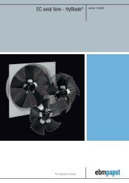
![Succesvol seminar [PDF] 314,2 kB - ebm-papst](https://img.yumpu.com/52907957/1/184x260/succesvol-seminar-pdf-3142-kb-ebm-papst.jpg?quality=85)

![magº 2013-1 [PDF] - ebm-papst](https://img.yumpu.com/52907773/1/190x252/mag-2013-1-pdf-ebm-papst.jpg?quality=85)