RXC31.1 Room controller Basic module
RXC31.1 Room controller Basic module
RXC31.1 Room controller Basic module

You also want an ePaper? Increase the reach of your titles
YUMPU automatically turns print PDFs into web optimized ePapers that Google loves.
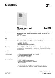
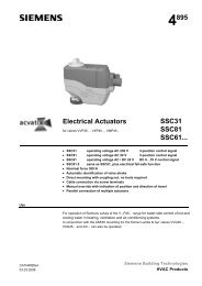
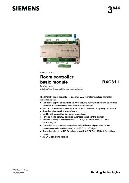
3 844DESIGO RXC<strong>Room</strong> <strong>controller</strong>,basic <strong>module</strong>for VAV plants,with LONMARK®-compatible bus communication<strong>RXC31.1</strong>The <strong>RXC31.1</strong> room <strong>controller</strong> is used for VAV room temperature control inindividual rooms. Control of supply and extract air, with volume control dampers or additionalcompact VAV <strong>controller</strong>s, with or without re-heaters Can be combined with extension <strong>module</strong>s for control of lighting and blinds Downloadable application software LONMARK®-compatible bus communications For use in the DESIGO building automation and control system Control of damper actuators with AC 24 V, 3-position or DC 0 … 10 Vcontrol signal Control of VAV compact <strong>controller</strong>s (with differential pressure sensor,volume <strong>controller</strong> and actuator) with DC 0 … 10 V signal Control of electric or LPHW re-heaters with AC 24 V or AC 24 V 3-positionsignals AC 24 V operating voltageCA2N3844en_0230 Jun 2009 Building Technologies
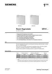
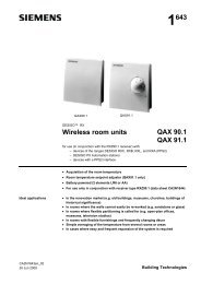
Integration into thebuilding automationand control systemWhen DESIGO RXC is integrated into a building automation and control systemadditional functions become available such as time scheduling, central control ofsetpoints, etc. (refer to the DESIGO INSIGHT documentation for further information).Types<strong>RXC31.1</strong>RXZ30.1<strong>Room</strong> <strong>controller</strong> for VAV systemsAccessories: Terminal coversOrderingWhen ordering please specify the quantity, product name and type code.The <strong>controller</strong>s are delivered with basic application 00031.The RXZ30.1 terminal covers are supplied in packs of 10 pairs and must be orderedseparately.Example:30 <strong>Room</strong> <strong>controller</strong>s for VAV systems <strong>RXC31.1</strong>/0003130 Pairs of terminal covers RXZ30.1CompatibilityThe <strong>RXC31.1</strong> can be used in conjunction with extension <strong>module</strong>s RXC40.1 for lightingcontrol (data sheet CA2N3842) and the RXC41.1 for the control of blinds (data sheetCA2N3843). For this purpose, the <strong>RXC31.1</strong> <strong>controller</strong> must be loaded with anapplication corresponding to the selected combination. Possible combinations and theassociated applications are described in the applications library (V1: CA2A3810,V2: CA110300).For operation, a room unit from the QAX… series may be used in conjunction withconventional momentary contact switches for lighting and blind control. Alternatively,the flexible room units, QAX50.1 or QAX51.1 may be used.See the RX hardware overveiw (CA2N3804) for a summary of the available fielddevices.Mechanical designThe <strong>RXC31.1</strong> <strong>controller</strong> consists of a housing base, a housing cover and the printedcircuit board with connection terminals. The <strong>controller</strong>s also have a connector base forthe extension <strong>module</strong>s, a tool socket, a service LED and a service pin.Plug-in ConnectionterminalsHousing coverPlug-in Connectionterminals80048Cable restraintsPlug-in connection terminalsfor LONWORKS® busConnector forextension <strong>module</strong>sHousing baseService LEDService pin.............Tool socket3/16Siemens <strong>RXC31.1</strong> – <strong>Room</strong> <strong>controller</strong> for VAV plants, basic <strong>module</strong> CA2N3844en_02Building Technologies 30 Jun 2009
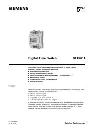
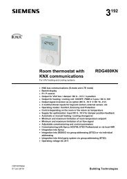
Terminal coversTerminal covers (RXZ30.1) are available as an option to protect the connectionterminals from physical contact and dirt. These covers also provide strain relief for thecables connecting the extension <strong>module</strong>s. The service LED remains visible when theterminal covers are in place, and the service pin can be operated with a pointedimplement. When fitting the terminal covers ensure that they lock into place.80049Removing the terminal coverLabelBar code, Code 128(Identification)Identification numberProtection standard3844Z01_01Temperature range(0 … 50 °C)Test date, series(Z, A, B, C…)Serial No.Factory-loadedapplicationDefinitiveapplicationLocationNoteConnection terminalsOptions for use of the labeling fields “Appl.” and “Loc.”: Hand-written entry of the location and the actual application … or Printed adhesive label (printed from the RXT10 commissioning and service tool)All connection terminals are detachable plug-in terminals. They are arranged so that,under normal circumstances, all incoming and outgoing cables can be connectedwithout crossing....Cable strain reliefThe conductors to the connection terminals can besecured with cable ties to the housing base.801704/16Siemens <strong>RXC31.1</strong> – <strong>Room</strong> <strong>controller</strong> for VAV plants, basic <strong>module</strong> CA2N3844en_02Building Technologies 30 Jun 2009
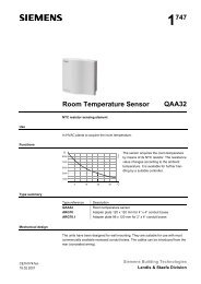
CommunicationLONWORKS® busThe <strong>RXC31.1</strong> <strong>controller</strong> communicates with other devices via the following interfaces: LONWORKS® bus (terminals CLA and CLB) for communication with: the PXR system <strong>controller</strong> or the NIDES.RX interface (to DESIGO) other DESIGO RXC devices LONMARK®-compatible third party devices (e.g. presence detector) PPS2 (terminals CP– and CP+): Interface to the QAX… room units. (In addition to PPS2, the LONWORKS® bus isalso looped to the tool socket on the room unit.) Tool socket (RJ45) on the <strong>controller</strong> or room unit, for: RXT10 commissioning and service tool (LONWORKS® bus) RXT20.1 service terminal (PPS2) PE bus (plug-in connection):Interface to the RXC40.1 and RXC41.1 extension <strong>module</strong>s.The diagram below shows the wiring of the LONWORKS® bus and PPS2 interface whena QAX… room unit is connected. It also shows the options for connecting the RXT10commissioning and service tool and the RXT20.1 service terminal.LonWorks® BusPPS2LonWorks® Bus3844A01enCP–CP+CLACLBQAX...<strong>RXC31.1</strong>CP–CP+CLACLBCLACLBPPS2LonWorks® BusToolPPS2ToolPPS2Service terminalRXT20.1LonWorks® BusRXT10.1PPS2Service terminalRXT20.1LonWorks® BusRXT10.1Service LEDService pinThe yellow service LED shows the current operational status of the <strong>controller</strong> by meansof different flashing patterns (see the RXT10 user manual, CA110338).The service pin is used to identify the <strong>controller</strong> in the commissioning phase. When thepin is pressed the <strong>controller</strong>’s identification number is transmitted to the RXT10commissioning and service tool.DisposalThe devices are classified as waste electronic equipment in terms of the European Directive2002/96/EC (WEEE) and should not be disposed of as unsorted municipal waste.The relevant national legal rules are to be adhered to.Regarding disposal, use the systems setup for collecting electronic waste.Observe all local and applicable laws.Siemens <strong>RXC31.1</strong> – <strong>Room</strong> <strong>controller</strong> for VAV plants, basic <strong>module</strong> CA2N3844en_02Building Technologies 30 Jun 20095/16
Engineering notesThe DESIGO RXC installation guide, document CA110334, contains the relevantengineering information for the LONWORKS® bus (topology, bus repeaters, bustermination, etc.) and for the selection and dimensions of connecting cables for thesupply voltage and field devices.See “Connection diagrams” for information on connecting field devices.AC 24 V supplyRXC40.1 and RXC41.1extension <strong>module</strong>sAC 24 V triac outputsExampleThe <strong>controller</strong> operates with an AC 24 V supply voltage (SELV / PELV). The supplycable must be protected with at least 10 A.The controlled devices (valves and damper actuators) are supplied directly from the<strong>controller</strong>. The maximum load on the outputs must not be exceeded (see “Technicaldata”). The power consumption of the connected devices must be taken into accountwhen sizing the transformer.The plug-in connection for the extension <strong>module</strong>s incorporates both thecommunications and the power supply. The power supply is limited to a maximum oftwo extension <strong>module</strong>s. The possible combinations are determined by the availableapplications. See the DESIGO RXC applications library (V1: CA2A3810,V2: CA110300). The simultaneous load on outputs Y1…Y6 must not exceed 24 VA The maximum load on each output must not exceed 12 VAEquipment Y1, Y2 (supply 1 3-position motorised actuator GDB13…1E 3 VAair)Y3, Y4 (extract 1 3-position motorised actuator GDB13…1E 3 VAair)Y5 (Heating) 2 thermic valve actuators, type STP72E 6 WY6 (Cooling) 2 thermic valve actuators, type STP72E 6 WSimultaneous load:2 motorised actuators (both ON6 VAcontinuously)2 thermic valve actuators * 6 W (12 W) **12 W (18 W)* The heating and cooling sequences are never operative simultaneously. Thereforeonly the actuators for one of the two sequences need to be included whencalculating the total load.** When cold, thermic valve actuators have a consumption of approximately 6 W. Amaximum of two thermic actuators may be connected to any one Y.. output.Compact VAV<strong>controller</strong>s If more than two compact VAV <strong>controller</strong>s are connected to the same output of the<strong>controller</strong> external auxiliary terminals must be used (only 2 wires perterminal). Only compact VAV <strong>controller</strong>s with a DC 0 … 10 V signal may be used.6/16Siemens <strong>RXC31.1</strong> – <strong>Room</strong> <strong>controller</strong> for VAV plants, basic <strong>module</strong> CA2N3844en_02Building Technologies 30 Jun 2009
MountingThe <strong>controller</strong> can be mounted in any orientation as follows:8006080061Rail mountingThe housing base is designed for snapmountingon DIN rails, type EN50022-35x7.5 (can be released with ascrewdriver).Surface mountingThere are four drill holes for screwmounting (see “Dimensions” for drillingdiagram). The housing base is fittedwith raised supports.Screws: Max. diameter 3.5 mm.When mounting note the following: Ensure adequate air circulation to dissipate heat generated during operation. Easy access is required for service personnel. Local installation regulations must be observed.The mounting instructions and a drilling template are printed on the <strong>controller</strong>packaging.Mounting withextension <strong>module</strong>sThe <strong>controller</strong> and extension <strong>module</strong>s (RXC40.1 and RXC41.1) must be mounted onthe same DIN rail.80050NoteIf different types of extension <strong>module</strong> are used they must be arranged in the followingorder: <strong>RXC31.1</strong> RXC40.1 RXC41.1CommissioningThe <strong>RXC31.1</strong> <strong>controller</strong> is commissioned with the RXT10 commissioning and servicetool. This is connected to the LONWORKS® bus via a tool socket (on the <strong>controller</strong> orroom unit).The commissioning procedure for the entire DESIGO RXC range is described in detailin the RXT10 user manual, document CA110338.LabelingThe labeling fields “Appl.” and “Loc.” on the <strong>controller</strong> are used to indicate theapplication actually loaded and the location of the <strong>controller</strong>, either in writing or by useof printed adhesive labels (see “Label” under “Mechanical design”).Siemens <strong>RXC31.1</strong> – <strong>Room</strong> <strong>controller</strong> for VAV plants, basic <strong>module</strong> CA2N3844en_02Building Technologies 30 Jun 20097/16
Function testNotesSTOP Note!All applications (including basic application 00031) allow direct interrogation of theinputs and control of the outputs using the RXT10 commissioning and service tool. Thismakes it possible to test the installation and to operate connected plant provisionallybefore the complete DESIGO RXC system is commissioned. The LONWORKS® bus plug (terminals 23 and 24) can be removed and reconnectedat any time, even while the <strong>controller</strong> is in operation. Only the original bus plug maybe used. Overloading the outputs Y1 … Y6 may cause the thermal fuse to trip and disable the<strong>controller</strong>. When the problem has been solved briefly disconnect and reconnect thepower supply. The <strong>controller</strong> will resume normal operation after a delay ofapproximately 10 minutes.Outputs Y1 … Y6 are not protected against accidental connection to AC 24 V.This can damage the triacs.Technical dataPower supply Operating voltage SELV / PELV AC 24 V ± 20 %Rated voltageAC 24 VFrequency50/60 HzInputsPower consumptionwithout field deviceswith field devices & extension <strong>module</strong>sInternal fuseSupply cable protection (external fuse)Signal inputs for volt-free contactsQuantityContact voltageContact currentContact transfer resistanceContact insulation resistanceNot suitable for pulse controlMeasured value input for temp. measurementQuantitySuitable temperature sensorsMeasuring rangeSensor currentResolutionAccuracyMeasured value inputs for DC 0 … 0.10 VQuantityMeasuring range (nominal)OverreachUnderreachResolutionSample rate6 VAMax. 33 VAThermal, automatic reset 10 A3 (D1, D2, D3)DC 33 VDC 8 mAMax. 100 Min. 50 k1 (X1) 1)LG-Ni 1000–40 ... 110 °C (2.1 ....2.6 mA)2.5 mA at 0 °C 0.2 KAt 25 °C 0,2 K3 (X1, U1, U2) 1)DC 0 ... 10 V3.0 V0 V20 mV 200 ms (U1, U2) 1 s (X1)1) X1 selected by option button in RXT10 tool: LG-Ni 1000 or DC 0 …10 V8/16Siemens <strong>RXC31.1</strong> – <strong>Room</strong> <strong>controller</strong> for VAV plants, basic <strong>module</strong> CA2N3844en_02Building Technologies 30 Jun 2009
OutputsCable connectionsTriac outputs AC 24 VQuantityOutput voltageOutput currentTotal nominal load(load on all outputs simultaneously)Control outputs DC 0 …10 VQuantityVoltage range (nominal)OverreachResolutionOutput currentResponse timeInterface to room unitMax. no. of connectable room unitsInterface type for RXT10Baud rate PPS2Baud rate LONWORKS®LONWORKS® busInterface typeTransceiverBaud rateBus topology and bus terminationInterface to extension <strong>module</strong>sPlug-in terminal blocksSolid conductorsStranded conductors withoutconnector sleevesStranded conductors with connector sleeves(DIN 46228/1)Max. tightening torqueConnecting cable for extension <strong>module</strong>sSingle cable lengthsSignal inputs D1 … D3Measured value input X1Triac outputs AC 24 V, Y1 ... Y6Control outputs DC 0 ... 10 V, YC1, YC2Interface to room unitCable type6 (Y1 ... Y6)AC 24 V on/off, PWM or 3-position(selected by switch)Max. 0.5 AMax. 24 VA2 (YC1, YC2)DC 0 ... 10 V5.5 V8 bits (50 mV)Max. 1mA100 msMax. 1LONWORKS®4.8 kBit/s78 kBit/sLONMARK®-compatible,electrically isolatedFTT-10A78 kBit/sSee Installation guide, CA110334Serial PE bus (power supply and data)Rising cage terminals1 x 0.2 ... 2.5mm 2or 2 x 0.2 ... 1.0 mm 21 x 0.2 ... 2.5mm 2or 2 x 0.2 ... 1.5 mm 21 x 0.25 ... 2.5mm 2or 2 x 0.25 ... 1.0 mm 20.6 Nm10-core ribbon cable, part of scope ofdeliverySee Installation guide, CA110334Max. 100 m with diameters 0.6 mmMax. 100 m with diameters 0.6 mmMax. 100m where A 1.5 mm 2Max. 100m where A 1.5 mm 2Max. 115 m where A= 0.75 mm 2(including tool connecting cable)4-core, twisted pair, unscreenedCompact VAV <strong>controller</strong> with PPS2interface(YC1, YC2)LONWORKS® busCable typeTool connecting cableMax. 230 m where A = 1.5mm 2 , for allcompact VAV <strong>controller</strong>s togetherSee Installation guide, CA110334See Installation guide, CA110334Housing protection standard Protection standard to EN 60529 IP30 with terminal cover fitted andwall mounted without DIN railAll other mounting arrangements: IP20Protection class Insulation protection class IIISiemens <strong>RXC31.1</strong> – <strong>Room</strong> <strong>controller</strong> for VAV plants, basic <strong>module</strong> CA2N3844en_02Building Technologies 30 Jun 20099/16
Ambient conditionsStandards and directivesEnvironmental compatibilityOperationTemperatureHumidityTransportTemperatureHumidityClass 3K5 to IEC 60,721-3-30 ... 50 °C< 85 % rhClass 2K3 to IEC 60,721-3-2– 25 ... 65 °C< 95 % rhProduct standard Automatic electroniccontrols for household and similar use EN 60730-1Electromagnetic compatibilityImmunity (domestic) EN 60730-1Emissions (domestic) EN 60730-1complianceMeets requirements of EMC directive 2004/108/ECUL complianceUL916C-Tick conformity (EMC) AS/NZS 61000-6-3The product environmental declarationCA2E3844 contains data on RoHS compliance,materials composition, packaging,environmental benefit, disposalDimensionsSee dimension diagramsWidth in DIN modular spacing units 8.5Weight Excluding packaging 0.28 kgISO 14001 (Environment)ISO 9001 (Quality)2002/95/EC (RoHS)Connection terminals1 2 3 4 5 6 7 8 9 10 11 12 13 14 15 16 17 18 19 20 21 22 23 24G0GGU1YC1G0G0YC2U2GGX1MD1AC 24 VGNDD2GNDD3CP–CP+CLACLBCLACLB0 ... 10 V IN0 ... 10 V OUT0 ... 10 V IN0 ... 10 V OUTAQT2 1 3 4QAX...LonWorks®BusMY1GY231 32 33Y3GY4Y5GY6G34 35 36 37 38 39 403844A02Power supplyG0 1 Controller groundG 2 AC 24 V supplyAnalogue inputs and outputsG 3 AC 24 V supply for sensors, actuators or compact VAV <strong>controller</strong>sU1 4 Measured value input for sensor (DC 0 … 10 V)YC1 5 DC 0 … 10 V control output for actuatorG0 6 Controller groundG0 7 Controller groundYC2 8 DC 0 … 10 V control output for actuatorU2 9 Measured value input for sensor (DC 0 … 10 V)G 10 AC 24 V supply for sensors, actuators or compact VAV <strong>controller</strong>s10/16Siemens <strong>RXC31.1</strong> – <strong>Room</strong> <strong>controller</strong> for VAV plants, basic <strong>module</strong> CA2N3844en_02Building Technologies 30 Jun 2009
Measured value inputs for temperature or air quality sensorsG 11 AC 24 V supply for sensorX1 12 Measured value input for sensor (LG-Ni 1000 or DC 0 … 10 V)M 13 Sensor groundSignal input for volt-free contactsD1 14 Signal inputGND 15 Signal groundD2 16 Signal inputGND 17 Signal groundD3 18 Signal input<strong>Room</strong> unitCP– 19 GroundCP+ 20 DataCLA 21 Data ACLB 22 Data BLONWORKS® bus (plug-in)CLB 23 Data BCLA 24 Data ATriac outputsY1 31 AC 24 V, 0.5 A switching outputG 32 AC 24 V actuator supplyY2 33 AC 24 V, 0.5 A switching outputY3 34 AC 24 V, 0.5 A switching outputG 35 AC 24 V actuator supplyY4 36 AC 24 V, 0.5 A switching outputY5 37 AC 24 V, 0.5 A switching outputG 38 AC 24 V actuator supplyY6 39 AC 24 V, 0.5 A switching outputG 40 AC 24 V actuator supplyTool socketStandard RJ45 tool socket for LONWORKS® devices.123456781 LONWORKS®, Data A (CLA)2 LONWORKS®, Data B (CLB)3 Not used4 Not used3206Z015 Not used6 Not used7 CP+8 CP–Connector forextension <strong>module</strong>sG0ADDRzATTNzVCCDG80052GRDYDATACLKDGG0 GroundADDRz Module addressATTNz HandshakeVCC DC 5 VDG Electronics groundGRDYDATACLKDGAC 24 VHandshakeDataClockElectronics ground11/16Siemens <strong>RXC31.1</strong> – <strong>Room</strong> <strong>controller</strong> for VAV plants, basic <strong>module</strong> CA2N3844en_02Building Technologies 30 Jun 2009
Connection diagramsN1G0G12G0GAC 24 VIndex AIndex BGU1YC1G03456GB1MpB1GYG0MY1GUCYG0MN2GUYCG0MN2G0YC2U2G78910MB1GpB2G0YGMY2G0YUCGMN3G0YCUGMN3GX1M111213BMTB3GU3G0AQB3.1D1GNDD2GNDD31415161718D1D2D3CP–CP+CLACLB19202122CP–CP+C+C–LonWorks® BusPPS2R1CLACLB2324LonWorks® BusY3GY4313233Y1GY2MY1Y3GY4343536Y1GY2MY3Y5GY6G37383940Y5Y6Y5.1Y6.1Y1GY2MY5.2Y5.33844A03N1<strong>RXC31.1</strong>N2, N3 1) VAV compact <strong>controller</strong> AC 24 V, 0...10 VB1, B2 1) Differential pressure sensorB3.1 Air quality sensorB3LG-Ni 1000 temperature sensorY1, Y2 1) Actuator for damper types 0... 10 VD1 ... D3 Volt-free contacts (window switch, occupancy sensor, etc.)R1QAX… room unitY1, Y3, Y5.2 AC 24 V 3-position damper actuatorsY5, Y6 AC 24 V thermic valve actuatorsY5.1, Y6.1 AC 24 V contactors for electric heating coilY5.3 Solid state relays Ac24V1) 1) Supply air devices to U1, YC1, and extract air devices to U2, YC2 (depending on application)12/16Siemens <strong>RXC31.1</strong> – <strong>Room</strong> <strong>controller</strong> for VAV plants, basic <strong>module</strong> CA2N3844en_02Building Technologies 30 Jun 2009
Notes Do not exceed the maximum simultaneous load on outputs Y1 … Y6(see “Engineering”). A power amplifier may be used to connect additional valve actuators to Y5 and Y6(see DESIGO RXC installation guide, CA110334). For information on actuators compatible with the <strong>RXC31.1</strong> <strong>controller</strong>, refer to therelevant application descriptions (see DESIGO RXC applications library(V1: CA2A3810, V2: CA110300). The AC 24 V supply (G) for devices such as the compact VAV <strong>controller</strong>s orDC 0 …10 V damper actuators, for example, can be derived either from the<strong>controller</strong> or from an external source (see DESIGO RXC installation guideCA110334). If the connected devices receive their supply from the <strong>controller</strong> thepower consumption of these devices must be taken into account when sizing thetransformer. The feedback signal (U or UC) from the VAV compact <strong>controller</strong> is not an essentialrequirement for the control in the <strong>RXC31.1</strong> <strong>controller</strong>.Parallel connection ofseveral thermicactuatorsUp to 2 thermic actuators can be connected directly to the room <strong>controller</strong>.In the case of more than 2 actuators a power amplifier is required.The same principle applies to output Y5.Note that the simultaneous load on outputs Y5 and Y6 must not exceed 9.5 VA.Power consumption at input X1 of the UA1T: 0.5 VA.STOP Note!Mixed operation: Connecting thermic actuators to the <strong>controller</strong> as well as to thepower amplifier is NOT allowed.Differing voltage of the power supply of the <strong>controller</strong> and the supply of the poweramplifier may cause big differences in the position of the valves.Connection to <strong>controller</strong>N100105 FGG0GG0AC 24 VY1GY5Y5.1N1 <strong>RXC31.1</strong>N2 UA1T (see data sheet CA2N3591)Y5 AC 24 V thermic valve actuatorY5.1 AC 24 V thermic valve actuatorSiemens <strong>RXC31.1</strong> – <strong>Room</strong> <strong>controller</strong> for VAV plants, basic <strong>module</strong> CA2N3844en_02Building Technologies 30 Jun 200913/16
Connection topower amplifierN1AC 24 VGG0AC 24 VGG000105 GGG0Y1GY5N21NSCOM8Y5.1Y5.323LSCOMY1COM76Y5.2Y5.44X1Y15N21NSCOM8Y5.5Y5.723LSCOMY1COM76Y5.6Y5.84X1Y15N1N2Y5Y5.x<strong>RXC31.1</strong>UA1T (see data sheet CA2N3591)AC 24 V thermic valve actuatorAC 24 V thermic valve actuator (max. 2 STA72E / STP72E actuators per Y1output on the UA1T)Notes The UA1T requires an AC 24 V supply voltage The UA1T is not suitable for the connection of 3-position actuators.14/16Siemens <strong>RXC31.1</strong> – <strong>Room</strong> <strong>controller</strong> for VAV plants, basic <strong>module</strong> CA2N3844en_02Building Technologies 30 Jun 2009
DimensionsAll dimensions in mmWithout terminalcovers35,390110623,913844M02With terminal covers50535,33,962 11611523844M01120Drilling diagram80056100135Siemens <strong>RXC31.1</strong> – <strong>Room</strong> <strong>controller</strong> for VAV plants, basic <strong>module</strong> CA2N3844en_02Building Technologies 30 Jun 200915/16
16/162000 - 2009 Siemens Switzerland Ltd.Subject to changeSiemens <strong>RXC31.1</strong> – <strong>Room</strong> <strong>controller</strong> for VAV plants, basic <strong>module</strong> CA2N3844en_02Building Technologies 30 Jun 2009