
Create successful ePaper yourself
Turn your PDF publications into a flip-book with our unique Google optimized e-Paper software.
DATAONLINE (UK) Ltd.9 Melbourne HousePriors Haw RoadCORBY NN17 5JGUKTel: 01536 264777Fax: 01536 264111www.dataonline.comDATAONLINE LLC10 Cottage StreetBERKELEY HEIGHTSNJ 07922USATel: 908 464 2646Fax: 908 464 3691www.dataonline.com<strong>THE</strong> <strong>WIRELESS</strong> <strong>DATAPORT</strong> <strong>CATALOGUE</strong>SEPTEMBER 2010
<strong>WIRELESS</strong> REMOTE TELEMETRY UNITS (WRTU) ANDASSOCIATED PRODUCTSINTRODUCTION ........................................................................................................................................3<strong>THE</strong> <strong>DATAPORT</strong> WRTU RANGE ................................................................................................................4DPG8xx ONE OR TWO CHANNEL LIQUID LEVEL GAUGE........................................................................5DPW422 DUAL CHANNEL <strong>WIRELESS</strong> WRTU ............................................................................................7DPW444 FOUR CHANNEL <strong>WIRELESS</strong> WRTU WITH 802.15.4 LOCAL RADIO NETWORK CAPABILITY ..8DPE460 SIX CHANNEL EXPLOSION PROOF <strong>WIRELESS</strong> WRTU WITHOUT A DISPLAY ............................9DPE421 TWO CHANNEL EXPLOSION PROOF <strong>WIRELESS</strong> WRTU WITH A SINGLE LCD DISPLAY ..........10DPR422 ONE or TWO CHANNEL 802.15.4 BASED REMOTE SENSOR....................................................11<strong>DATAPORT</strong> ACCESSORIES ........................................................................................................................12DPA910 DUAL CHANNEL ALARM RELAY BOARD..................................................................................12<strong>THE</strong> DPW & DPG RANGE ACCESSORIES ................................................................................................12DPA921 DUAL CHANNEL ANALOG REMOTE INDICATOR ................................................................13DPA911 FOUR CHANNEL ALARM RELAY BOARD ............................................................................13DPA940 DUAL CHANNEL RELAY ISOLATION MODULE ....................................................................14DPA930/1 SINGLE CHANNEL DIGITAL REMOTE INDICATOR ............................................................14DPA960 (115 VAC) MAINS POWER SUPPLY MODULE ......................................................................15DPA950 DUAL CHANNEL GALVANIC ISOLATION MODULE ............................................................15DPA960 (115 VAC) MAINS POWER SUPPLY MODULE ......................................................................16DPA961 (230 VAC) MAINS POWER SUPPLY MODULE ......................................................................17DPA964 UNIVERSAL ISOLATED DC POWER SUPPLY MODULE ........................................................18DPA965 UNIVERSAL HEATED POWER SUPPLY MODULE..................................................................19DPA966-Li VEHICULAR DC POWER SUPPLY MODULE......................................................................20DPA970/1 REMOTE INDICATOR RS232 DRIVER MODULE ................................................................21DPA975 4-20 mA ACTIVE CURRENT LOOP OUTPUT MODULE ........................................................21DPA981 USB LOCAL PROGRAMMING ADAPTOR ............................................................................22DPA976 4-20 mA PASSIVE CURRENT LOOP OUTPUT MODULE ......................................................22DPA420 802.15.4 RADIO CONTROLLER MODULE ............................................................................23DPA410 GPS MODULE FOR USE WITH MOBILE ASSETS ..................................................................23DPA440 FOUR CHANNEL RELAY ISOLATION MODULE ....................................................................24DPA430 ANALOG EXPANSION MODULE ..........................................................................................24DPA460 FOUR CHANNEL DIGITAL INPUT MODULE..........................................................................25DPA450 FOUR CHANNEL GALVANIC ISOLATION MODULE..............................................................25APPENDIX “A” – DPW422 BLOCK DIAGRAM ........................................................................................26APPENDIX “B” - TYPICAL DPW422 WRTU ASSEMBLY ..........................................................................27APPENDIX “C” - DPA930 WIRING DIAGRAM ........................................................................................28APPENDIX “D” - DP262 MATRIX 3 ........................................................................................................292
INTRODUCTIONDATAONLINE LLC has been designing and manufacturing Remote Telemetry systems since 1989 and hasa wealth of expertise in the installation and management of gathering asset data from industrialpremises. Since these early days of telemetry, we have seen the rise of mobile telephony and theinternet and have embraced both technologies to put us in the forefront of web-based telemetry.The DPW range of products reflects the “state of the art” in ultra low power wireless remote telemetryand can be powered from internal primary batteries, solar panels and rechargeable batteries, or directlyfrom external power supplies ranging from 6 to 60 Volts DC or 115 and 230 Volts AC. There is a heatedpower supply option for use in extremely cold climates that will maintain correct operation of the LCDdisplays and the internal battery.The WRTU’s can use the GSM network, the Reflex network, the CDMA network, the Vistar Satellitenetwork or WiFi to communicate back the DataOnline’s web servers to collect key inventory informationfrom the field. We currently supply GSM based units to most of the countries in the developed world.The use of low power 802.15.4 radio links with the new DPW42x WRTU’s further enhances the wirelessnature of our range of telemetry products. This new range allows the DPW424 WRTU to be mounted ina convenient control room with up to four remote tanks connected completely wirelessly to our website by using the DPR422 802.15.4 radio based Remote Sensors.The DPW42x WRTU can be used with the DPA410 GPS module and a GSM multiband radio to track assetssuch as containers around the world and report on a variety of parameters, including the contents ofan integral vessel, shock loading, shipping delays, etc.Another major advantage of the DPW424 WRTU is its ability to mix wired and wireless signals into thesame unit. This means that one DPW424 unit could be fitted on a tank and then receive the level signalsfrom 3 adjacent tanks using the DPR422 802.15.4 radio based Remotes with the absolute minimumamount of site wiring. As these 4 tank levels would now be sent through one shared radio, thecommunication costs are also kept to a minimum.The latest version of the wireless Dataport is the DPW444 unit with 4 analog inputs as standard and alarge 4 line LCD display with status indicators showing communication status, battery condition, etc.This model is only powered by lithium batteries, both primary and secondary cells in order to use themost up-to-date technology.3
<strong>THE</strong> <strong>DATAPORT</strong> WRTU RANGEThe DPG80x Liquid Level Gauges (LLG’s) and the DPW range of Wireless Remote Telemetry Units(WRTU’s) were designed to fit inside a weatherproof polycarbonate enclosure with the printed circuitboard in the lid of the box with the liquid crystal display fitted directly on this pcb. This methodologyallows the lid to be removed for installation on site by disconnecting the battery lead and the powersource lead. The standard one or two channel variants of the DPWxxx usually have their sensors fittedto the base of the enclosure and just need the attachment of two impulse lines from the tank beingmonitored to become operational. DPR422 802.15.4 radio based remote units are just as easy to install.Primary power is supplied by an external solar panel that is used to recharge an internal 6 Volt Lead-Acid or 8 Volt Lithium-Ion battery. Where solar power is impractical, such as indoor installations, aninternal miniature power supply module is used in place of the solar panel. The internal power supplymodules are for use with 6 to 60 Volts DC supplies or 115 & 230 Volts AC. The alternative is to use alithium thionyl chloride primary battery pack mounted in the base of the enclosure to give up to fiveyears of operation before the battery pack needs to be changed.The DPW WRTUs accept inputs from 4 to 20 mA transmitters that are usually powered by the Dataportitself. The DPW WRTUs can also use the CDMA network or the GSM network. They can use SIM cardsfrom any network provider.When the 4 to 20 mA transmitters are powered from local plant based systems it is important to checkthat connecting up both transmitter loops into the Dataport’s common ground input circuitry will notcause problems with the control system itself. If there is any doubt, we would recommend fitting theDPA940 or DPA950 two channel isolation module directly to the DPW800 board. The DPA440 or DPA450four channel isolation modules are mounted in a separate enclosure that is usually mounted next to theassociated Dataport.The DPW WRTU’s can be used with the DPA920/1 or DPA930/1 remote display units to give local tanklevel information away from the actual Dataport installation, such as found on sites with multiple tankson one or more concrete plinths.The DPW range of Digital Liquid Level Gauges (DLLG’s) and WRTU’s can be fitted with a variety of “addon”boards. As mentioned above, the DPA940 and DPA950 boards can be fitted to the main DPW800and DPW400 boards to produce relay or galvanic isolation from external control systems. They can alsobe fitted with the DPA910 two channel ALARM RELAY board to give local alarms in the shape of a pairof opening or closing relay contacts as the tank level drops above or below a critical point or thepressure in the tank crosses a preset threshold.Where the DPW series WRTU’s are used in POLL mode so that they support ad hoc enquiries, it isrecommended that they are powered from the Lithium-Ion/Solar rechargeable battery option or aminiature mains power supply.There are a number of external power supply options that can be fitted inside the DPW enclosures. TheDPA960 is used for 115 VAC supplies, the DPA961 for 230 VAC supplies and the DPA964-xx for 6 to 60VDC supplies.If the environment where the unit will be installed is very cold and air temperatures below -20ºC arepossible for long periods, we would recommend that the unit is fitted with the DPA965 heated powersupply board. The heater built into this power supply board will maintain an internal box temperatureabove -20ºC even if the outside air temperature falls as low as -40ºC. The DPA965 heated power supplywill operate from an AC supply between 85 and 265 VAC at 50 or 50 Hz.See the block diagram in Appendix A for a representative sample of how the various accessories can beused with the DPWxxx WRTU’s.4
<strong>THE</strong> DPG8XX ONE OR TWO CHANNEL LIQUID LEVEL GAUGEThis single or dual channel Dataport LLG accepts inputs from oneor two 4 to 20 mA transmitters that can be powered from theDataport or from an external control system. Two pushbuttons onthe front of the enclosure are used to put the display into “FILL”mode to show the rapidly changing tank level or to change themode of the display(s). The unit is usually battery powered butthere are a variety of other power supply options. The solar panel(when fitted) and any field wiring cables are brought into theenclosure from below using IP67 cable glands.SPECIFICATIONSMeasurement accuracy0.5% of span (full scale).Operating temperatureInputsProgrammingMeasurement interval-40°F to +150°F. Long term operation below -5°F requires the use of theDPA965 heated power supply option.One or Two 4-20mA current loops normally supplied from the integralsensors.Programmable via an RS232 adaptor for SPAN and ZERO calibration, FILLmode duration and ALARM point thresholds.Certain versions of the software allow the service engineer to set theSPAN of the display on-site.Adjustable from once every 15 minutes to once per day.Alarm thresholds2 settable alarm points per input channel.Display(s)1 or 2 six digit 17mm high LCD display panels.Power supplyEnclosure ratingInternal 7 Volts primary cell battery pack, solar panel and 2.5 Ahrechargeable battery.NEMA 4X or IP67ApprovalsUnit is CE approved.5
<strong>THE</strong> DPW811 SINGLE CHANNEL BASIC <strong>WIRELESS</strong> WRTUThis single channel Dataport WRTU accepts inputs from one 4 to 20mA transmitter that can be powered from the Dataport or from anexternal control system. Two pushbuttons on the front of theenclosure are used to put the display into “FILL” mode to show therapidly changing tank level or to change the mode of the display(s).The unit can be fitted with either a GSM or a REFLEX radio and avariety of power supply options. The solar panel and any fieldwiring cables are brought into the enclosure from below using IP67cable glands.SPECIFICATIONSMeasurement accuracy0.1% of span (full scale).Operating temperatureInputs-40°F to +150°F. Long term operation below -5°F requires the use of theDPA965 heated power supply option.One 4-20mA current loop normally supplied from the integral sensor.Measurement intervalAdjustable from once every 15 minutes to once per day.Reporting intervalAlarm thresholdsAdjustable from once per day to once per hour.10 settable alarm points per input channel.CommunicationsGSM cellular network (inc. GPRS) or the REFLEX paging network.Display(s)1 six digit 17mm high LCD display panel with optional yellow LEDbacklighting.Power supply Solar panel and 2.5 Ah rechargeable battery, AC mains supplies for 115and 230 VAC or internal 7 Volts primary cell battery pack.Enclosure ratingNEMA 4X or IP67ApprovalsUnit is CE approved, power supply to UL/TUV/CE, GSM radio to FTA, FCC,DOC, PTCRB, R&TTE, GCF & BABT, Reflex radio to FCC parts 2, 15, 24 & 90.6
<strong>THE</strong> DPW422 DUAL CHANNEL <strong>WIRELESS</strong> WRTUThis dual channel Dataport WRTU accepts inputs from one or two4 to 20 mA transmitters that can be powered from the Dataport orfrom an external control system. Two pushbuttons on the front ofthe enclosure are used to put the display into “FILL” mode to showthe rapidly changing tank level or to change the mode of thedisplay(s). The unit can be fitted with either a GSM or a REFLEXradio and a variety of power supply options. The solar panel andany field wiring cables are brought into the enclosure from belowusing IP67 cable glands.SPECIFICATIONSMeasurement accuracy0.1% of span (full scale).Operating temperatureInputs-40°F to +150°F. Long term operation below -5°F requires the use of theDPA965 heated power supply option.Two 4-20mA current loops normally supplied from the integral sensors.Measurement intervalAdjustable from once every 15 minutes to once per day.Reporting IntervalAlarm thresholdsAdjustable from once per day to once per hour.10 settable alarm points per input channel.CommunicationsGSM cellular network (inc. GPRS) or the REFLEX paging network.Display(s)1 or 2 six digit 17mm high LCD display panels with optional yellow LEDbacklighting.Power supply Solar panel and 2.5 Ah rechargeable battery, AC mains supplies for 115and 230 VAC or internal 7 Volts primary cell battery pack.Enclosure ratingNEMA 4X or IP67ApprovalsUnit is CE approved, power supply to UL/TUV/CE, GSM radio to FTA, FCC,DOC, PTCRB, R&TTE, GCF & BABT, Reflex radio to FCC parts 2, 15, 24 & 90.7
<strong>THE</strong> DPW444 4 CHANNEL <strong>WIRELESS</strong> WRTU with 802.15.4 localradio network capabilityThis is the latest addition to the product range and is a fourchannel Dataport that accepts inputs from one to four 4 to 20 mAtransmitters that are normally powered from the Dataport or from1 to 4 remote 802.15.4 radio based slave units. Two pushbuttonson the front of the enclosure are used to put the display into “FILL”mode to show the rapidly changing tank level or to change themode of the display(s). The unit can be fitted with either a GSM,CDMA, Satellite or a REFLEX radio and a variety of power supplyoptions. The solar panel and any field wiring cables are broughtinto the enclosure from below using IP67 cable glands.The DPW444 Master unit can display the contents of all 4 channelswhether, wired or wireless. Extensive system information is alsoavailable from this display when put into ‘DEBUG’ mode.The unit is converted to an 802.15.4 radio MASTER by the simpleaddition of the DPA420 accessory. This little module is selfcontainedand does not normally need an external antenna forreliable site operation. The associated 802.15.4 radio based Remoteunits do not usually require external antennas.SPECIFICATIONSMeasurement accuracy0.1% of span (full scale).Operating temperatureInputs-40°F to +150°F. Long term operation below -5°F requires the use of theDPA965 heated power supply option.Two 4-20mA current loops normally supplied from the integral sensors.Measurement intervalAdjustable from once every 15 minutes to once per day.Reporting intervalAdjustable from once per day to once per hour.Alarm thresholds10 settable alarm points per input channel.CommunicationsGSM cellular network (inc. GPRS) or the CDMA network.Display(s)4 lines of six digit 16mm high LCD display panel with 4 status indicatorsPower supplyEnclosure ratingSolar panel and 2.5 Ah rechargeable lithium battery, AC mains suppliesfor 115 and 230 VAC or internal 7 Volts primary lithium battery pack.NEMA 4X or IP67ApprovalsUnit is CE approved, power supply to UL/TUV/CE, GSM radio to FTA, FCC,DOC, PTCRB, R&TTE, GCF & BABT, Reflex radio to FCC parts 2, 15, 24 & 90.8
<strong>THE</strong> DPE460 6 CHANNEL EXPLOSION PROOF <strong>WIRELESS</strong> WRTUwithout a displayThis version of the Dataport is a six channel WRTU that accepts inputsfrom one up to four 4 to 20 mA transmitters that are normally poweredfrom the Dataport plus 2 thermocouples that are used to detect cold gasexiting from a vent pipe. Two pushbuttons on the top of the board areused to put the display into “DEBUG” mode for commissioningpurposes. The unit can be fitted with a GSM, radio and a primary lithiumbattery pack.The unit is normally fitted with a GPS radio that keeps track of the unitanywhere worldwide. In order for this feature to function correctly, thetop of the enclosure needs to have a clear view of the sky.Closed versionSPECIFICATIONSMeasurement accuracy0.1% of span (full scale).Operating temperature-40°F to +150°F.InputsMeasurement intervalReporting intervalFour 4-20mA current loops supplied from the integral power supply plus2 thermocouples for cold gas venting detection.Adjustable from once every 15 minutes to once per day.Adjustable from once per day to once per hour.Alarm thresholds10 settable alarm points per input channel.CommunicationsGSM cellular network (inc. GPRS) plus a worldwide GPS capability.Display(s)Power supplyNo display visible from outside the enclosure, but a small 8 character LCDis fitted for commissioning purposes.Internal 7 Volts, 45 Ahr lithium thionyl chloride battery pack.Enclosure ratingExplosion proof as per FM/CSA/ATEX/IECEx, NEMA 4X / IP68ApprovalsUnit is CE approved, GSM radio to FTA, FCC, DOC, PTCRB, R&TTE, GCF &BABT9
<strong>THE</strong> DPE421 2 CHANNEL EXPLOSION PROOF <strong>WIRELESS</strong> WRTUwith a single LCD displaySPECIFICATIONSMeasurement accuracy0.1% of span (full scale).Operating temperature-40°F to +150°F.InputsTwo 4-20mA current loops supplied from the integral power supply.Measurement intervalReporting intervalAdjustable from once every 15 minutes to once per day.Adjustable from once per day to once per hour.Alarm thresholds10 settable alarm points per input channel.CommunicationsGSM cellular network (inc. GPRS).Display(s)1 by 6 digit LCD display visible from outside the enclosure.Power supplyInternal 7 Volts, 45 Ahr lithium thionyl chloride battery pack.Enclosure ratingExplosion proof as per FM/CSA/ATEX/IECEx, NEMA 4X / IP68ApprovalsUnit is CE approved, GSM radio to FTA, FCC, DOC, PTCRB, R&TTE, GCF &BABT10
<strong>THE</strong> DPW & DPG RANGE ACCESSORIESThe DPW range of WRTU’s and the DPG80x DLLG’s can be used with the growing range of accessoriesto enhance and/or expand the capabilities of the overall installation.The DPA920 or DPA930 remote display units can be used with the DPWxxx WRTU’s to give local tanklevel information away from the actual Dataport installation, such as found on sites with multiple tankson one or more concrete plinths.When the 4 to 20 mA transmitters are powered from local plant based systems it is important to checkthat connecting up both transmitter loops into the Dataport’s common ground input circuitry will notcause problems with the control system itself. If there is any doubt, we would recommend fitting theDPA940 or DPA950 two channel isolation module directly to the DPWxxx board.The large selection of miniature internal power supplies allow the internal lead-acid battery to becharged from 115 VAC and 230 VAC mains supplies or any DC power source between 6 and 60 VDC.The DPW4xx WRTU now allows complete wireless operation by using up to four DPR422 Remote802.15.4 radio based Sensors to gather data from tanks on a site without using ANY interconnectingcables. Typically the DPW424 host would be sited in the plant control room to give local operator accesswith up to four remote sensors attached to plant based 4-20 mA transmitters. Battery life of theseremote sensors can be up to 5 years.<strong>DATAPORT</strong> ACCESSORIES<strong>THE</strong> DPA910 DUAL CHANNEL ALARM RELAY BOARDThis small printed circuit board fits on to the 4 fixing pillars on the DPW series controller boards andconnects into the “ALARM” connector on these boards.There are 2 independent relays on the board, each with a changeover contact available at the screwterminals. The relay contacts are rated at 0.3A at 115 VAC or 1.0A at 30 VDC, but are intended to driveinto low power alarm control systems. If the contacts are used to switch loads above 5 Watts, thenexternal suppressors should be fitted across the screw terminals.The operation of each relay is under the control of the microprocessor on the DPW800 series controllerboard and they would typically operate when the tank level went below a certain level or the pressurein the tank dropped below some preset value. See the operator' manual for the specific Dataport as tohow to program these relays.12
<strong>THE</strong> DPA911 FOUR CHANNEL ALARM RELAY BOARDThis small printed circuit board fits on to the 4 fixing pillars on the DPW series controller boards andconnects into the “ALARM” connector on these boards.There are 4 independent relays on the board, each with a changeover contact available at the screwterminals. The relay contacts are rated at 0.3A at 115 VAC or 1.0A at 30 VDC, but are intended to driveinto low power alarm control systems. If the contacts are used to switch loads above 5 Watts, thenexternal suppressors should be fitted across the screw terminals.The operation of each relay is under the control of the microprocessor on the DPW4xx series controllerboard and they would typically operate when the tank level went below a certain level or the pressurein the tank dropped below some preset value. See the operator' manual for the specific Dataport as tohow to program these relays.<strong>THE</strong> DPA921 DUAL CHANNEL ANALOG REMOTE INDICATORThis dual channel Remote Indicator is used in conjunction withthe range of Dataport WRTU’s and accepts an input from one4 to 20 mA transmitter that is powered from the Dataport orfrom an external control system.The unit is loop powered and SPAN and ZERO setting isachieved through the Programming port and allows the units ofdisplay to be set up to a maximum of 999999.The DPA921 can be supplied with a DT1 differential pressuresensor for remote tank applications and then has the ordercode DPG921.13
<strong>THE</strong> DPA930/1 SINGLE CHANNEL DIGITAL REMOTE INDICATORThis single channel Remote Indicator is used in conjunction withthe range of Dataport WRTU’s and repeats the reading shown onits host Dataport WRTU’s display. A small 2 pole programmingswitch is used to set which of the four possible WRTU channeldisplays to copy.The unit is normally powered from the host Dataport but can alsobe powered from its own internal battery pack that will maintainoperation for up to 5 years when the host Dataport is batterypowered itself.The DPA931 variant has an RJ45 connector directly on the printedcircuit board that allows standard CAT5 cables to be used toconnect the unit to its remote host Dataport.The DPA930/1 can be supplied with a DT1 differential pressuresensor for remote tank applications and then has the order codeDPR930/1.<strong>THE</strong> DPA940 DUAL CHANNEL RELAY ISOLATION MODULEThis two channel RELAY ISOLATION board is used in conjunction with the range of DPW DataportWRTU’s and isolates the analog inputs from each other. Note that each time an analog channel issampled, the Dataport is electrically connected to that specific input.The unit is powered from the Dataport to which it is attached and when the analog input channel ispowered, the DPDT relay is energised and puts a 100 ohm resistor into the external 4 to 20 mA loop.When the analog input channel is powered down, the relay de-energises and leaves the external loopintact.Two on-board LEDs are used to indicate when a reading cycle is in progress.14
<strong>THE</strong> DPA950 DUAL CHANNEL GALVANIC ISOLATION MODULEThis two channel GALVANIC ISOLATION board is used in conjunction with the range of DPW800Dataport WRTU’s and isolates the external analog inputs from each other and the host Dataport. Sincethe WRTU printed circuit board needs to be modified to use this module, this is NOT suitable for fieldupgrades.The unit is powered from the Dataport to which it is attached and when the analog input channel ispowered, the isolation circuitry is energised and measures the voltage across the 10 ohm resistor that isinserted into the external 4 to 20 mA loop.Span adjustment is factory set by two miniature potentiometers and Zero adjustment is performed bythe host Dataport in software. Two on-board LEDs are used to indicate when a measurement cycle is inprogress.<strong>THE</strong> DPA960 (115 VAC) MAINS POWER SUPPLY MODULEThis miniature power supply modulefits on the internal chassis plate insidethe DPW800 range of WRTU’s andreplaces the Solar Panel as the primebattery charging power source.This module is often fitted to its hostDataport where the solar panel cannotsee enough of the sun, e.g.installations inside buildings, or wherethe Dataport is set up to supportcontinuous polling.be fused at 0.1 Amps maximum outside of the Dataport.The integral red LED indicates thepresence of the mains supply and thatthe output is not short-circuited. Thetransformer used in the power supplyis inherently short-circuit proof, butthe mains supply to the module must15
<strong>THE</strong> DPA960 (115 VAC) MAINS POWER SUPPLY MODULEThis miniature power supply modulefits on the internal chassis plate insidethe DPW800 range of WRTU’s andreplaces the Solar Panel as the primebattery charging power source.This module is often fitted to its hostDataport where the solar panel cannotsee enough of the sun, e.g.installations inside buildings, or wherethe Dataport is set up to supportcontinuous polling.The integral red LED indicates thepresence of the mains supply and thatthe output is not short-circuited. Thetransformer used in the power supplyis inherently short-circuit proof, butthe mains supply to the module mustbe fused at 0.1 Amps maximum outsideof the Dataport.TECHNICAL SPECIFICATIONSSTANDARD UNIT MIN TYP. MAX UNITSOutput Voltage 5 7.5 9.5 VoltsOutput Current 40 80 120 mAOperating temperature -40ºC +50ºC CentigradeInput voltage (50-60Hz) 100 115 125 VAC16
<strong>THE</strong> DPA961 (230 VAC) MAINS POWER SUPPLY MODULEThis miniature power supply modulefits on the internal chassis plate insidethe DPW800 range of WRTU’s andreplaces the Solar Panel as the primebattery charging power source.This module is often fitted to its hostDataport where the solar panel cannotsee enough of the sun, e.g.installations inside buildings, or wherethe Dataport is set up to supportcontinuous polling.The integral red LED indicates thepresence of the mains supply and thatthe output is not short-circuited. Thetransformer used in the power supplyis inherently short-circuit proof, butthe mains supply to the module mustbe fused at 0.1 Amps maximum outsideof the Dataport.TECHNICAL SPECIFICATIONSSTANDARD UNIT MIN TYP. MAX UNITSOutput Voltage 5 7.5 9.5 VoltsOutput Current 40 80 120 mAOperating temperature -40ºC +50ºC CentigradeInput voltage (50-60Hz) 200 230 250 VAC17
<strong>THE</strong> DPA964 UNIVERSAL ISOLATED DC POWER SUPPLY MODULEThis miniature power supply module fitson the internal chassis plate inside theDPW range of WRTU’s and replaces theSolar Panel as the prime battery chargingpower source.This module is often fitted to its hostDataport where the solar panel cannotsee enough of the sun, e.g. installationsinside buildings, or where the Dataport isset up to support continuous polling.The integral yellow LED indicates thepresence of the DC supply and that theoutput is not short-circuited. The moduleis inherently short-circuit proof, but theDC supply to the module should be fusedat 0.5 Amps maximum outside of theDataport.SPECIFICATIONSSTANDARD UNIT MIN TYP. MAX UNITSOutput Voltage 5 7.5 9.5 VoltsOutput Current 40 60 80 mAOperating temperature -40ºC +50ºC CentigradeInput voltage 85% 100% 125% VDCInput to Output isolationvoltage withstand1500 VDCAll units comply with EN 55022 class A and FCC level A regulations.DPA964-6DPA964-12DPA964-24DPA964-48for supplies between 5 and 10 Volts DC.for supplies between 10 and 20 Volts DC.for supplies between 20 and 30 Volts DC.for supplies between 30 and 60 Volts DC.18
<strong>THE</strong> DPA965 UNIVERSAL HEATED POWER SUPPLY MODULERemote DisplayConnectorHeater2 Parts MainsConnector1 AhrLead-AcidBatteryThis power supply module fits inside the DPWrange of WRTU’s and replaces the Solar Panel andthe 2.5 AHr rechargeable lead-acid battery. It alsosupports the use of the DPA930 remote displayswithout any further equipment.This module is fitted to its host Dataport where theambient air temperature falls below -20ºC for longperiods of time. These conditions can be found inthe north of Europe and around the USA/Canadaborder. The use of this power supply supportscontinuous polling of the Dataport.The integral yellow LED indicates the presence ofthe battery charging supply and that the output isnot short-circuited. The red LED indicates that theinternal heater is switched off and the box is“warm”. The module is inherently short-circuitproof, but the mains supply to the module must befused at 1 Amp maximum outside of the Dataport.TECHNICAL SPECIFICATIONSInput voltage rangeInput frequency rangeInput current heater OFFInput current heater ONExternal fuseAmbient TemperaturerangeEMI/RFI conducted85 – 264 VAC47 – 440 Hz30mA @ 115 VAC/ 35mA @ 230 VAC typical200mA @ 115 VAC/ 120mA @ 230 VAC typical1.5 A slow blow type recommended-40 °C to +50 °CEN55022 class B, FCC part 15 level BEMC ComplianceESD to IEC/EN61000-4-2 4kV / 8kVRF immune to IEC/EN61000-4-3 3V / mFast transients to IEC/EN61000-4-4 1kVSafety standards UL 1950, IEC 60950, EN 60950Output supplyTemperature controlComms portRemote Display connector8.3 Volts max @ 80 mA max used to trickle charge the internal lead-acidbattery9 Watt heater switched on at an internal box temperature of +3 °C andoff at +7 °C3.6 VDC logic level signals from the Dataport hostRS232 transmit & receive lines to remote displays and a 4.2 VDC powersupply rated at 100 mA max.19
<strong>THE</strong> DPA966-LI VEHICULAR DC POWER SUPPLY MODULEThis miniature power supply module fitson the internal chassis plate inside theDPW range of WRTU’s and replaces theSolar Panel as the prime battery chargingpower source. It is only for use with 7.4Volt rechargeable Lithium-ion batteries.The integral GREEN LED indicates thepresence of the DC supply and that theoutput is not short-circuited. The moduleis inherently short-circuit proof, but theDC supply to the module should be fusedat 0.5 Amps maximum outside of theDataport.SPECIFICATIONSSTANDARD UNIT MIN TYP. MAX UNITSOutput Voltage 8.1 8.2 8.3 VoltsOutput Current 120 140 160 mAOperating temperature -40ºC +50ºC CentigradeInput voltage 12 24 48 VDCInput to Output isolationvoltage withstand1500 VDCAll units comply with EN 55022 class A and FCC level A regulations.20
<strong>THE</strong> DPA970/1 REMOTE INDICATOR RS232 DRIVER MODULEThese small boards fit on the chassis plate inside a DPWxxx WRTU and supports operation of the DPA930or DPA931 Remote Indicators.Two flying leads connect the board to the host Dataport and a five way screw connector is used toterminate the field wiring from up to four remote DPA930 indicators. The board is powered from theDataport’s power supply and the remote indicator can also be powered from this power supply, via thefive way field wiring.A newer version of this board, the DPA971, has an RJ45 connector onboard to allow direct connectionof CAT5 cables between the Dataport and the remote display. The DPA931 Remote Indicator also has anRJ45 connector allowing CAT5 cable connectivity.<strong>THE</strong> DPA975 4-20 mA ACTIVE CURRENT LOOP OUTPUT MODULEThis small printed circuit board fits on to the 4 fixing pillars on the DPW series controller boards andconnects into the “ALARM” connector on these boards.The 4-20 mA current loop output is under the control of the host Dataport’s microcontroller and can bespanned independently of the main displays in the host. In order for this module to drive the currentloop continuously, the host Dataport MUST be mains powered using one of the DPA96x power supplymodules.Zero and span adjustment of the board itself is achieved by two on-board miniature potentiometers inthe factory and these should NOT be adjusted in the field. Change the Zero and/or Span values throughthe Dataport’s programming port or “over the air” using the DataOnline web site.21
<strong>THE</strong> DPA976 4-20 MA PASSIVE CURRENT LOOP OUTPUT MODULEThis small printed circuit board fits on to the 4 fixing pillars on the DPW series controller boards andconnects into the “ALARM” connector on these boards.The 4-20 mA current loop output is under the control of the host Dataport’s microcontroller and can bespanned independently of the main displays in the host. In order for this module to function correctly,the external current loop must be powered by a DC supply between 8 and 30 VDC.Since this board is effectively powered by an external source, it does not require any significant powerfrom the host Dataport. Consequently, the host Dataport can be Solar powered or primary batterypowered, as is normal for the range of DLLG’s.<strong>THE</strong> DPA981 USB LOCAL PROGRAMMING ADAPTORThis programming adaptor hasa ’chip’ fitted inside the USBconnector and is used withnotebooks, laptops, PC’s, etc.to allow certain parametersstored in the DPW Dataport’smemory to be changed.It is powered from the USBport on the host computer andwill normally be mapped intoone of the COM ports on thePC and operate at 9600 Baud.Plugging this programmer intothe PROG port on the Dataportwill put the Dataport into the“local communication mode”and the Dataport will “signon”at 9600 Baud. See theoperator’s manual for theindividual DPW programmingcapabilities.22
<strong>THE</strong> DPA410 GPS MODULE FOR USE WITH MOBILE ASSETSThis small module “plugs on” to the main pcb of the DPW4xx WRTU and allows the Dataport to findout its position on the earth using the GPS satellite network and the onboard COPERNICUS radiomodule. An active GPS antenna must be mounted with a reasonable view of the sky and then pluggedinto the mating socket on the DPA410 board.When this module is fitted to the DPW4xx board, the DPA420 802.15.4 Radio Controller module cannotbe used.<strong>THE</strong> DPA420 802.15.4 RADIO CONTROLLER MODULEThis small module “plugs on” to the main pcb of the DPW844 WRTU andallows the Dataport to communicate at 2.4 GHz with up to 4 DPR4xxRemote Sensor units. The module has its own onboard antenna and doesnot normally need an external antenna for correct operation. The 4Remotes can each be up to 1000 feet away from the DPW444 WRTU underideal conditions.When this module is fitted to the DPW4xx board, the DPA410 GPS modulecannot be used.23
<strong>THE</strong> DPA430 ANALOG EXPANSION MODULEThis module “plugs on” to the main pcb of the DPW42x WRTU and extends the unit’s hardwiredchannels from 2 to 4. It contains a DC-DC converter that produces an 18 VDC supply for powering 2external 4-20 mA transmitters. These new channels (3 & 4) behave in an identical manner to channels 1& 2 in that they can be individually programmed for recording rate, alarm thresholds, sensor delay, etc.When this module is fitted to the DPW44x board, the following modules cannot be used:DPA910 dual alarm relays, DPA940 relay isolator, DPA950 galvanic isolator and the DPA975 and DPA9764-20 mA current output modules.<strong>THE</strong> DPA440 FOUR CHANNEL RELAY ISOLATION MODULEThis four channel RELAY ISOLATION board is used in conjunction with the DPW444 Dataport WRTU andisolates the analog inputs from each other. Note that each time an analog channel is sampled, theDataport is electrically connected to that specific input.The unit is powered from the Dataport to which it is attached and when the analog input channel ispowered, the DPDT relay is energised and puts a 100 ohm resistor into the external 4 to 20 mA loop.When the analog input channel is powered down, the relay de-energises and leaves the external loopintact.Four on-board LEDs are used to indicate when a reading cycle is in progress.24
<strong>THE</strong> DPA450 FOUR CHANNEL GALVANIC ISOLATION MODULEThis four channel GALVANIC ISOLATION board is used in conjunction with the DPW444 Dataport WRTUand isolates the analog inputs from each other and the Dataport itself.The unit is powered from the Dataport to which it is attached and puts a 10 ohm resistor into theexternal 4 to 20 mA loop. There is no connection between each channel and any other channel and the10 ohm resistor is permanently connected in series with the instrument loop.Four on-board LEDs are used to indicate when a reading cycle is in progress.<strong>THE</strong> DPA460 FOUR CHANNEL DIGITAL INPUT MODULEThis 4 channel Digital Input board is used in conjunction with the DPW444 Dataport WRTU and monitorsthe states of up to four volt-free contacts. The contacts are scanned continuously by the onboardprocessor and it signals any change of state to the host microcontroller when it is interrogated every 2seconds. This means that the unit cannot count pulses whose duration is less than 2 seconds, but it willreact to shorter pulses as events, that would be reported to the web service.Because this module only uses the EXP connector on the Dataport board, it can be used in conjunctionwith some of the other Dataport Accessories. Consult the sales department for more information.25
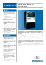
1234512345APPENDIX “A” – DPW422 BLOCK DIAGRAMLOCAL PROGRAMMINGADAPTOR FOR PDAs,etc.DPA981SOLAR PANELD DCHANNEL 1 DISPLAYDPW422 <strong>DATAPORT</strong>1234566 VDC RECHARGEABLEBATTERY9 VDC PRIMARYBATTERYMAINS POWEREDBATTERY CHARGERC OPTIONAL CHANNEL 2 DISPLAY 123456CDPA960EXPANSIONBOARDAREAUNIVERSAL MAINS POWEREDHEATED POWER SUPPLY& RS232 LINE DRIVERDPA965B BDPA910 DUAL RELAY BOARDFOR LOCAL ALARMSLINE DRIVERMODULEDPA970RS232DPA930 REMOTE DISPLAY MODULEFOR SECOND TANK LEVEL, etc.DPA940 2 CHANNEL ISOLATIONBOARD FOR SHARED SIGNALSDPA920 CURRENT LOOPINDICATOR andREMOTE DISPLAYA DATAONLINE (UK) Ltd.A9 MELBOURNE HOUSEPRIORS HAW ROADCORBY NN17 5JGSINGLE CHANNEL 4-20mA OUTPUTMODULE FOR LOCAL PLC, DCS,etcDPA976Title<strong>DATAPORT</strong> DPW422 EXPANSION CAPABILITIESSize Document Number RevD051890B AFriday, April 29, 2005Date: Sheet of 1 126
APPENDIX “B” - TYPICAL DPW422 WRTU ASSEMBLYSolar PanelMounted Ona 180º SwivelPlateStainless SteelMounting PlateFill ButtonTank LevelDisplayPressure SensorTank PressureDisplayMechanicalPressure GaugePortMode ButtonExternal PowerLeadDifferentialPressure SensorGas LineConnectionLiquid LineConnection27
.APPENDIX “C” - DPA930 WIRING DIAGRAM54321DPW4xx based <strong>DATAPORT</strong> WRTUMaximum cable length is 250 feet (75M)when using CAT5 twisted pair cable.DPA930 or DPA931REMOTE DISPLAYD DFILL+VE1 RX12 GND23 FILL4 FILLspecial leadPROG1123456special leadSW112CSI-LC229 board5prog5 core cableC CPORTFILLDPA970 or DPA971DRIVER MODULEREDBROWNBLACKWHITEGREENOPTIONAL4-20 mA SENSOR+VEB B-VEDP+DP-LOOP+LOOP-TIE+VEIP2ORANGEBLUE.A ADATAONLINE LLCTitleWiring diagram for a <strong>DATAPORT</strong> WRTU & an DPA930 REMOTE DISPLAYSize Document Number RevA.Date: Monday, March 03, 2008Sheet 1 of 154321.1234.LINE.1234512.SENSOR1234.INPUT212328
APPENDIX “D” - DP262 MATRIX329
SPECIFICATIONSDATAONLINE LLC10 Cottage StreetBERKELEY HEIGHTSNJ 07922USATel: 908 464 2646Fax: 908 464 3691www.dataonline.comDATAONLINE (UK) Ltd.9 Melbourne HousePriors Haw RoadCORBY NN17 5JGUKTel: 01536 264777Fax: 01536 264111www.dataonline.com<strong>THE</strong> <strong>WIRELESS</strong> <strong>DATAPORT</strong> <strong>CATALOGUE</strong>SEPTEMBER 2010