City 3 Controller - Came UK
City 3 Controller - Came UK
City 3 Controller - Came UK

Create successful ePaper yourself
Turn your PDF publications into a flip-book with our unique Google optimized e-Paper software.
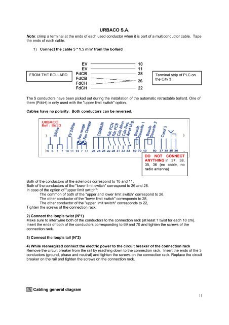
URBACO S.A.Note: crimp a terminal at the ends of each used conductor when it is part of a multiconductor cable. Tapethe ends of each cable.1) Connect the cable 5 * 1.5 mm² from the bollardFROM THE BOLLARDTerminal strip of PLC onthe <strong>City</strong> 3The 5 conductors have been picked out during the installation of the automatic retractable bollard. One ofthem (FdcH) is only used with the "upper limit switch" option.Cables have no polarity. Both conductors can be reversed.DO NOT CONNECTANYTHING in 37, 38,35, 36 (no cable, noradio antenna)Both of the conductors of the solenoids correspond to 10 and 11.Both of the conductors of the "lower limit switch" correspond to 26 and 28.In case of the option of "upper limit switch":The common of both of the "upper and lower limit switch" correspond to 26,The other conductor of the "lower limit switch" corresponds to 28,The other conductor of the "upper limit switch" corresponds to 22,Tighten the screws of the connection rack.2) Connect the loop's twist (N°1)Make sure to intertwine both of the conductors to the connection rack (at least 1 twist for each 10 cm).Insert the ends of both of the conductors corresponding to 69 and 70 and tighten the screws of theconnection rack.3) Connect the loop's tail (N°2)4) While reenergized connect the electric power to the circuit breaker of the connection rackRemove the circuit breaker from the rail by reaching down to the connection rack. Insert the ends of the 3conductors (ground, phase and neutral) and tighten the screws on the connection rack. Replace the circuitbreaker on the rail and tighten the screws on the connection rack.4.1 Cabling general diagram11