SECTION 819 MICROTUNNELING AND PIPE-JACKED TUNNELS ...
SECTION 819 MICROTUNNELING AND PIPE-JACKED TUNNELS ...
SECTION 819 MICROTUNNELING AND PIPE-JACKED TUNNELS ...
- No tags were found...

You also want an ePaper? Increase the reach of your titles
YUMPU automatically turns print PDFs into web optimized ePapers that Google loves.
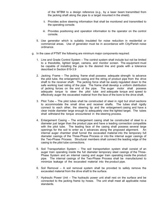
of the MTBM to a design reference (e.g., by a laser beam transmitted from<br />
the jacking shaft along the pipe to a target mounted in the shield).<br />
ii. Provides active steering information that shall be monitored and transmitted to<br />
the operating console.<br />
iii. Provides positioning and operation information to the operator on the control<br />
console.<br />
5. Use generator which is suitably insulated for noise reduction in residential or<br />
commercial areas. Use of generator must be in accordance with City/Parish noise<br />
ordinance.<br />
g. In the case of PTMT the following are minimum major components required:<br />
1. Line and Grade Control System – The control system shall include but not be limited<br />
to a theodolite, lighted target, camera, and monitor screen. The equipment must<br />
be capable of installing the pipe to the desired line and grade with a tolerance<br />
described in Section <strong>819</strong>-3.9<br />
2. Jacking Frame – The jacking frame shall possess adequate strength to advance<br />
the pilot tube, the enlargement casing and the string of product pipe from the drive<br />
shaft to the receiver shaft. The jacking force shall be easily regulated down to the<br />
safe working load rating of the pipe. The frame shall develop a uniform distribution<br />
of jacking forces on the end of the pipe. The auger motor shall possess<br />
adequate torque to steer the pilot tube and adequate torque and speed to<br />
effectively auger the excavated material from the face of the bore to the drive shaft.<br />
3. Pilot Tube – The pilot tubes shall be constructed of steel in rigid but short sections<br />
to accommodate the small drive and receiver shafts. The tubes shall rigidly<br />
connect to each other, the steering tip and the enlargement casing and have a<br />
clear inside diameter large enough to adequately view the lighted target. The tubes<br />
shall withstand the torque encountered in the steering process.<br />
4. Enlargement Casing – The enlargement casing shall be constructed of steel to a<br />
diameter just larger than the product pipe and have a leading connection compatible<br />
with the pilot tube. The leading face of the casing shall possess several large<br />
openings for the soil to enter as it advances along the proposed alignment. An<br />
internal auger chamber shall funnel the excavated material into the temporary full<br />
diameter casings of the Three-Phase Process or into the internal auger casings of<br />
the Two-Phase Process. Structural members shall connect the leading edge of the<br />
casing to the pilot tube connections.<br />
5. Soil Transportation System – The soil transportation system shall consist of an<br />
auger train operating inside the full diameter temporary steel casings of the Three-<br />
Phase System and an internal casing and auger train operating inside the product<br />
pipe. The internal casings of the Two-Phase Process shall be manufactured to<br />
minimize leakage of the excavated material into the product pipe.<br />
6. Soil Removal – A soil removal system shall be provided to safely remove the<br />
excavated material from the drive shaft to the surface.<br />
7. Hydraulic Power Unit – The hydraulic power unit shall rest on the surface and be<br />
connected to the jacking frame by hoses. The unit shall meet all applicable noise<br />
standards.