CylindriCal and Tapered roller Bearings
Bower Cylindrical and Tapered Roller Bearings - NTN Bearing
Bower Cylindrical and Tapered Roller Bearings - NTN Bearing
- No tags were found...

You also want an ePaper? Increase the reach of your titles
YUMPU automatically turns print PDFs into web optimized ePapers that Google loves.
Roller <strong>Bearings</strong><br />
Load Analysis<br />
In many applications, the load <strong>and</strong> speed considerations<br />
are critical to the bearing selection. Methods of analyzing<br />
load sources <strong>and</strong> the resolution of these loads into<br />
bearing reactions are presented below. Frequently, the<br />
methods to evaluate the magnitude of the load <strong>and</strong> the<br />
speed are based on a history of performance of similar<br />
equipment. Such st<strong>and</strong>ard approaches are essential<br />
when the bearings are exposed to a full spectrum of<br />
loads <strong>and</strong> speeds <strong>and</strong>/or a wide variety of work<br />
schedules.<br />
The first step in the process is to determine the<br />
magnitude <strong>and</strong> direction of the loads which the bearings<br />
are required to support. Loads may originate from a<br />
variety of sources including dead weight, belts, chains,<br />
sprockets, gears, imbalance, etc. Each load source is<br />
discussed below:<br />
Dead weight may be either concentrated or distributed<br />
over a given area. For most bearing applications,<br />
distributed loads may be resolved into a single<br />
concentrated load acting vertically through the center<br />
of gravity. For example, the location of the center of<br />
gravity in an automobile will determine load distribution<br />
between the four wheels. The load at each wheel is<br />
distributed over the area of contact between the tire<br />
<strong>and</strong> the road. This load may be considered concentrated<br />
at the geometric center of the contact area acting normal<br />
to the road surface.<br />
Belts are encountered in a wide variety of industrial<br />
applications. They are used for both power transmission<br />
<strong>and</strong> conveyor systems. Power transmission belts may<br />
be flat, “V” sectioned, or cogged for timing applications.<br />
Conveyor belts are normally flat for moving palletized<br />
loads or contoured to a trough shape for bulk materials.<br />
Friction between the drive pulley <strong>and</strong> the belt transmits<br />
the motive power in all applications except for cogged<br />
timing belts. To assure that sufficient frictional forces<br />
exist, the belts must be installed with the proper amount<br />
of preload tension. Belt manufacturers provide<br />
guidelines to establish the correct value for the preload.<br />
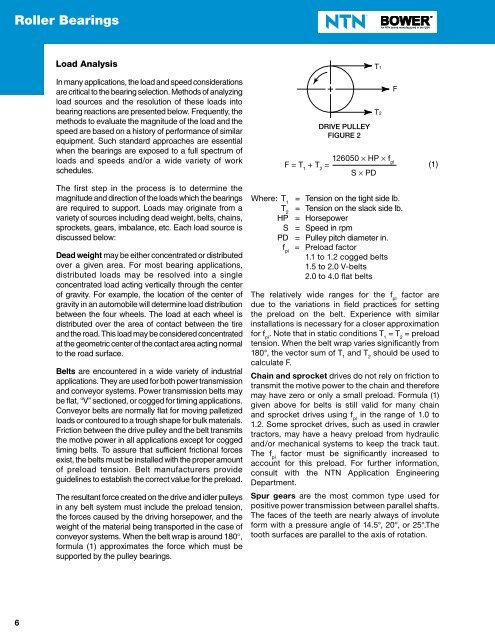
The resultant force created on the drive <strong>and</strong> idler pulleys<br />
in any belt system must include the preload tension,<br />
the forces caused by the driving horsepower, <strong>and</strong> the<br />
weight of the material being transported in the case of<br />
conveyor systems. When the belt wrap is around 180,<br />
formula (1) approximates the force which must be<br />
supported by the pulley bearings.<br />
DRIVE PULLEY<br />
FIGURE 2<br />
Where: where T 1<br />
= Tension on the tight side lb.<br />
T 2<br />
= Tension on the slack side lb.<br />
HP = Horsepower<br />
S = Speed in rpm<br />
PD = Pulley pitch diameter in.<br />
f pl<br />
= Preload factor<br />
1.1 to 1.2 cogged belts<br />
1.5 to 2.0 V-belts<br />
2.0 to 4.0 flat belts<br />
T1<br />
T2<br />
F = T 1<br />
+ T 2<br />
= <br />
126050 HP f pl<br />
S PD<br />
The relatively wide ranges for the f pl<br />
factor are<br />
due to the variations in field practices for setting<br />
the preload on the belt. Experience with similar<br />
installations is necessary for a closer approximation<br />
for f pl<br />
. Note that in static conditions T 1<br />
= T 2<br />
= preload<br />
tension. When the belt wrap varies significantly from<br />
180°, the vector sum of T 1<br />
<strong>and</strong> T 2<br />
should be used to<br />
calculate F.<br />
Chain <strong>and</strong> sprocket drives do not rely on friction to<br />
transmit the motive power to the chain <strong>and</strong> therefore<br />
may have zero or only a small preload. Formula (1)<br />
given above for belts is still valid for many chain<br />
<strong>and</strong> sprocket drives using f pl<br />
in the range of 1.0 to<br />
1.2. Some sprocket drives, such as used in crawler<br />
tractors, may have a heavy preload from hydraulic<br />
<strong>and</strong>/or mechanical systems to keep the track taut.<br />
The f pl<br />
factor must be significantly increased to<br />
account for this preload. For further information,<br />
consult with the NTN Application Engineering<br />
Department.<br />
Spur gears are the most common type used for<br />
positive power transmission between parallel shafts.<br />
The faces of the teeth are nearly always of involute<br />
form with a pressure angle of 14.5°, 20°, or 25°.The<br />
tooth surfaces are parallel to the axis of rotation.<br />
F<br />
(1)<br />
6