CylindriCal and Tapered roller Bearings
Bower Cylindrical and Tapered Roller Bearings - NTN Bearing
Bower Cylindrical and Tapered Roller Bearings - NTN Bearing
- No tags were found...

You also want an ePaper? Increase the reach of your titles
YUMPU automatically turns print PDFs into web optimized ePapers that Google loves.
Engineering Section<br />
An Imbalance Force Force is generated is generated when when a mass a rotates mass<br />
on rotates an axis on from an axis its center offset from of gravity. its center This imbalance, of gravity.<br />
called This imbalance, a centrifugal called force, a will centrifugal put an additional force, will load put on<br />
the an additional support bearings. load on This the load support direction bearings. will remain This<br />
stationary load direction in regard will remain to the rotating stationary ring. in The regard magnitude to the<br />
of rotating the centrifugal ring. The force magnitude may be determined of the centrifugal from equation force<br />
16. may be determined from equation 16.<br />
S 2<br />
Wt r S2<br />
C.F. = (16)<br />
lb.<br />
3.52 10 4<br />
The evaluation of a combination of rotating loads <strong>and</strong><br />
stationary loads is a complex calculation <strong>and</strong> should<br />
be referred to the NTN Application Engineering<br />
Department.<br />
THE CALCULATION THE CALCULATION OF BEARING OF LOADS<br />
Before the actual BEARING bearing loads LOADS can be calculated, the<br />
bearing spread must be defined. For a shaft supported<br />
Before the actual bearing loads can be calculated, the<br />
on two bearings, the bearing spread is defined as the<br />
bearing spread must be defined. For a shaft supported<br />
distance between the two points which are considered<br />
on two bearings, the bearing spread is defined as the<br />
to be the center of support for the load on the bearing.<br />
distance between the two points which are considered<br />
For cylindrical <strong>roller</strong> bearings, the point is defined as<br />
to be the center of support for the load on the bearing.<br />
the intersection of the axis of rotation of the bearings<br />
For cylindrical <strong>roller</strong> bearings, the point is defined as<br />
<strong>and</strong> a plane normal to the axis through the midpoint of<br />
the intersection of the axis of rotation of the bearings<br />
the <strong>roller</strong> length. See Figure 7.<br />
<strong>and</strong> a plane normal to the axis through the midpoint of<br />
the <strong>roller</strong> length. See Figure 7.<br />
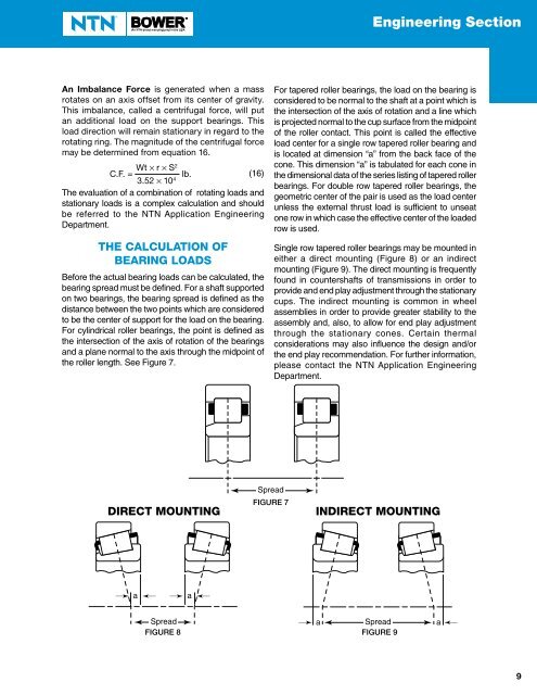
For tapered <strong>roller</strong> bearings, the load on the bearing is<br />
considered to be normal to the shaft at a point which is<br />
the intersection of the axis of rotation <strong>and</strong> a line which<br />
is projected normal to the cup surface from the midpoint<br />
of the <strong>roller</strong> contact. This point is called the effective<br />
load center for a single row tapered <strong>roller</strong> bearing <strong>and</strong><br />
is located at dimension “a” from the back face of the<br />
cone. This dimension “a” is tabulated for each cone in<br />
the dimensional data of the series listing of tapered <strong>roller</strong><br />
bearings. For double row tapered <strong>roller</strong> bearings, the<br />
geometric center of the pair is used as the load center<br />
unless the external thrust load is sufficient to unseat<br />
one row in which case the effective center of the loaded<br />
row is used.<br />
Single row tapered <strong>roller</strong> bearings may be mounted in<br />
either a direct mounting (Figure 8) or an indirect<br />
mounting (Figure 9). The direct mounting is frequently<br />
found in countershafts of transmissions in order to<br />
provide <strong>and</strong> end play adjustment through the stationary<br />
cups. The indirect mounting is common in wheel<br />
assemblies in order to provide greater stability to the<br />
assembly <strong>and</strong>, also, to allow for end play adjustment<br />
through the stationary cones. Certain thermal<br />
considerations may also influence the design <strong>and</strong>/or<br />
the end play recommendation. For further information,<br />
please contact the NTN Application Engineering<br />
Department.<br />
DIRECT MOUNTING<br />
Spread<br />
FIGURE Figure 77<br />
INDIRECT MOUNTING<br />
a<br />
a<br />
Spread a<br />
Spread a<br />
FIGURE Figure 8 FIGURE Figure 9<br />
9