

HPA A-Series O'Manual_13062006.indd
HPA A-Series O'Manual_13062006.indd
HPA A-Series O'Manual_13062006.indd

Create successful ePaper yourself
Turn your PDF publications into a flip-book with our unique Google optimized e-Paper software.
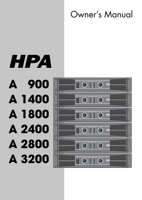
A 900<br />
A 1400<br />
A 1800<br />
A 2400<br />
A 2800<br />
A 3200<br />
Owner’s Manual<br />
ON<br />
OFF<br />
ON<br />
OFF<br />
ON<br />
OFF<br />
ON<br />
OFF<br />
ON<br />
OFF<br />
ON<br />
OFF<br />
POWER<br />
POWER<br />
POWER<br />
POWER<br />
POWER<br />
POWER<br />
0 10<br />
CHANNEL 1<br />
0 10<br />
CHANNEL 1<br />
0 10<br />
CHANNEL 1<br />
0 10<br />
CHANNEL 1<br />
0 10<br />
CHANNEL 1<br />
0 10<br />
CHANNEL 1<br />
PROFESSIONAL POWER AMPLIFIER<br />
PROTECT<br />
CLIP<br />
-10dB<br />
-20dB<br />
SIGNAL<br />
ACTIVE<br />
PROFESSIONAL POWER AMPLIFIER<br />
PROTECT<br />
CLIP<br />
-10dB<br />
-20dB<br />
SIGNAL<br />
ACTIVE<br />
PROFESSIONAL POWER AMPLIFIER<br />
PROTECT<br />
CLIP<br />
-10dB<br />
-20dB<br />
SIGNAL<br />
ACTIVE<br />
PROFESSIONAL POWER AMPLIFIER<br />
PROTECT<br />
CLIP<br />
-10dB<br />
-20dB<br />
SIGNAL<br />
ACTIVE<br />
PROFESSIONAL POWER AMPLIFIER<br />
PROTECT<br />
CLIP<br />
-10dB<br />
-30dB<br />
SIGNAL<br />
ACTIVE<br />
PROFESSIONAL POWER AMPLIFIER<br />
PROTECT<br />
CLIP<br />
-10dB<br />
-20dB<br />
SIGNAL<br />
ACTIVE<br />
0 10<br />
CHANNEL 2<br />
0 10<br />
CHANNEL 2<br />
0 10<br />
CHANNEL 2<br />
0 10<br />
CHANNEL 2<br />
0 10<br />
CHANNEL 2<br />
0 10<br />
CHANNEL 2<br />
<strong>HPA</strong><br />
A900<br />
<strong>HPA</strong><br />
A1400<br />
<strong>HPA</strong><br />
A1800<br />
<strong>HPA</strong><br />
A2400<br />
<strong>HPA</strong><br />
A2800<br />
<strong>HPA</strong><br />
A3200
�������<br />
�� ������� ���� �� ����� ������� �� ��� ��� ���� ���� ���� �� ������� ����� ����������<br />
�� ����� ������ ������ ��� ������ ��� �� ����� �������� �� ������� ����� ���������<br />
�� ������� ���� �� ����� ������� �� ��� ������ ���� ��������� �� ���� �� ���������<br />
�� ������ ���������� ������ ����� ���� ����� ���� �� ���� ���� ����� �������<br />
��<br />
��<br />
��<br />
��<br />
��<br />
��<br />
��<br />
��<br />
��<br />
���<br />
���<br />
���<br />
���<br />
���<br />
���<br />
���<br />
���<br />
���� �������� ����� ���� ������<br />
���� ������� ������ �� �����<br />
������� ��������� �� �������� ��<br />
����� ��� ���� �� ��� ��������<br />
�� ����������� ����������<br />
�������� ������ ��� ���������<br />
��������� ���� ��� �� ��<br />
���������� ��������� ��<br />
���������� � ���� �� ��������<br />
����� �� ��������<br />
�������<br />
���� �� �������� �����<br />
�� ��� ����<br />
�������� �� ������ ��� ���� ��<br />
�������� ������ �� ��� ������<br />
����� ��� ����� �� �����<br />
����������� ����� ������� �����<br />
������� �� ��������� �������<br />
����������<br />
��� ����������� ����� ������<br />
�� ����������� �������� ��<br />
�������� �� ����� ��� ���� ��<br />
��� �������� �� ���������<br />
��������� ��� �����������<br />
����������� ������������ ��<br />
��� ���������� ������������<br />
��� ����������<br />
��������� ������ ������������<br />
���� ����� �������������<br />
���� ����� �������������<br />
���� ��� ���������<br />
������ ��� �������������<br />
�� ��� ��� ���� ��������� ���� ������<br />
����� ���� ���� ��� ������<br />
�� ��� ����� ��� ���������� ��������� ������� �� ���������� ���� ��� ������������� �������������<br />
�� ��� ������� ���� ��� ���� ������� ���� �� ���������� ���� ���������� ������� �� ����� ��������<br />
���������� ����������� ���� ������� �����<br />
�� ��� ������ ��� ������ ������� �� ��� ��������� �� ��������� ���� ����� � ��������� ���� ��� ���<br />
������ ���� ��� ����� ���� ��� ������ � ��������� ���� ���� ��� ��� ������ ��� � ����� ��������� ������<br />
��� ���� ����� �� ��� ����� ����� ��� �������� ��� ���� ������� �� ��� �������� ���� ���� ��� ��� ���� ����<br />
������� ������� �� ����������� ��� ����������� �� ��� �������� �������<br />
������� ��� ����� ���� ���� ����� ������ �� �� ������� ����������� �� ��� ������ ����������� ������<br />
������� ��� �� ��� ����� ����� ���� ���� ���� ��� ����������<br />
���� ��� ����������������������� ��������� �� ��� �������������<br />
��� ���� ���� ��� ����� ������ ������� �������� �� ����� ��������� �� ��� ��������<br />
������ �� ���� ���� ��� ���������� ���� � ���� �� ����� ��� ������� ����<br />
������ ��� �������������� ����������� �� ����� ������ ���� ���������<br />
������ ��� ��������� ������ ���������� ���� �� ���� ������ ��� ���� ������� �� �����<br />
����� ��� ��������� �� ��������� ���������� ������� �� �������� ���� ��� ��������� ��� ���� ������� ��<br />
��� ���� ���� �� ����� ������ ���� �� ���� �� �������� ������ ��� ���� ������� �� ������� ���� ������<br />
���� ��� ��������� ��� ���� ������� �� ���� �� ��������� ���� ��� ������� ��������� �� ��� ����<br />
��������<br />
���� ��������� ����� ��� �� ������� �� �������� �� ��������� ����� ��� ���� �� ������ ������ ���� ������<br />
���� �� ����� ����� �� ������ �� ��� ����������<br />
���������� ������� ��������� ������ ����� ���� ����� ���� ���� ���� ����� �������<br />
������ ���� � ���� ����������� ����������� ������ ��� ������ �����
A 900 / 1400 / 1800 / 2400 / 2800 / 3200<br />
Table of Contents<br />
Introduction ………………………………………………………… 2<br />
Features ……………………………………………………………… 3<br />
Front Panel Controls ………………………………………………… 4<br />
Rear Panel Controls ………………………………………………… 5<br />
Protection …………………………………………………………… 7<br />
Setup ………………………………………………………………… 8<br />
Connections ………………………………………………………… 10<br />
Wiring ………………………………………………………………… 12<br />
Specifi cations ……………………………………………………… 13<br />
Table of Contents<br />
1
Introduction<br />
Introduction<br />
2<br />
ON<br />
OFF<br />
POWER<br />
0 10<br />
CHANNEL 1<br />
A 900 / 1400 / 1800 / 2400 / 2800 / 3200<br />
HEAVY DUTY PROFESSIONAL AMPLIFIER<br />
PROFESSIONAL POWER AMPLIFIER<br />
PROTECT<br />
CLIP<br />
-10dB<br />
-20dB<br />
SIGNAL<br />
ACTIVE<br />
A 900 / 1400 / 1800 / 2400 / 2800 / 3200<br />
Welcome.<br />
Congratulation and thank you for the purchasing A <strong>Series</strong>, a state-of-the-art heavy duty<br />
professional amplifi er.<br />
These amplifi er are designed to provide a big impact in sound reproduction and to<br />
produce the best and highest quality audio at an affordable price. We wish you great<br />
enjoyment and satisfaction when using your amplifi er, whether you are an installation,<br />
or reinforcement engineer.<br />
Unpacking and Installation<br />
Although it is neither complicated to install nor diffi cult to operate your amplifi er, a few<br />
minutes of your time is required to read this manual for a properly wired installation<br />
and becoming familiar with its features and how to use them. Please take a great care<br />
in unpacking your set and do not discard the carton and other packing materials. They<br />
may be needed when moving your set and are required if it ever becomes necessary to<br />
return your set for service. Never place the unit near radiator, in front of heating vents,<br />
to direct sun light, in excessive humid or dusty location to avoid damages and to guaranty<br />
a long reliable use. Connect your unit with the system components according to<br />
the description on the following pages.<br />
0 10<br />
CHANNEL 2<br />
<strong>HPA</strong><br />
A3200
A 900 / 1400 / 1800 / 2400 / 2800 / 3200<br />
Features<br />
<strong>HPA</strong> A-<strong>Series</strong> amplifi er delivers the following power ratings.<br />
A 900 2 x 210 Watts at 8 ohm, 2 x 320 Watts at 4 ohm and 2 x 420 Watts at 2 ohm<br />
A 1400 2 x 300 Watts at 8 ohm, 2 x 450 Watts at 4 ohm and 2 x 700 Watts at 2 ohm<br />
A 1800 2 x 400 Watts at 8 ohm, 2 x 600 Watts at 4 ohm and 2 x 900 Watts at 2 ohm<br />
A 2400 2 x 550 Watts at 8 ohm, 2 x 750 Watts at 4 ohm and 2 x 1200 Watts at 2 ohm<br />
A 2800 2 x 600 Watts at 8 ohm, 2 x 900 Watts at 4 ohm and 2 x 1400 Watts at 2 ohm<br />
A 3200 2 x 700 Watts at 8 ohm, 2 x 1100 Watts at 4 ohm and 2 x 1600 Watts at 2 ohm<br />
2-channel, parallel or bridged mono operating modes for fl exible application 900<br />
Watts for A 900, 1400 Watts for A 1400, 1800 Watts for A 1800, 2400 Watts for A<br />
2400, 2800 Watts for A 2800 and 3200 Watts for A 3200.<br />
Independent limiters for each channel reduce distortion.<br />
Independent input level controls for each channel allow precision adjustments.<br />
Precise signal and clip LED indicators to monitor performance, allow you to correct<br />
for overloading (clipping) condition.<br />
Low-frequency fi lters (40 Hz) remove rumble and subsonic frequency.<br />
Twin-tunnel and two temperature-sensitivity forced-air cooling system to maintain a<br />
low.<br />
Balanced XLR or balanced 1/4-inch TRS Combination input connector for each<br />
channel and LINK ports.<br />
5-way output binding posts or Speaker connectors enable secure operation.<br />
High-current toroidal transformer for absolute reliability.<br />
Independent DC and thermal overload protection on each channel automatically protects<br />
amplifi er and speaker.<br />
The A series can be mounted in any standard 19” rack.<br />
Features<br />
3
Front Panel Controls<br />
Front Panel Controls<br />
1. Rack Mounting Ears<br />
Two front panel mounting holes are provided<br />
on each mounting ear.<br />
2. Fan Vent<br />
A series amplifi ers are cooled by two (except<br />
for A 900) rear-mounted fans. Cool air is<br />
fl owed through the front fan fi lters, reducing<br />
the temperature of the inside components<br />
while forcing the heat out the rear vents.<br />
Never block these vents and keep them clean<br />
at all time.<br />
3. AC Power Switch<br />
This switch controls the units main power.<br />
4. Signal Indicators<br />
These green and yellow LED will illuminate<br />
to indicate that a signal is present at the<br />
amplifi er input, and that the signal is being<br />
amplifi ed.<br />
5. Clip Indicators<br />
These red LED will illuminate at the clipping<br />
threshold. If it lights frequently, you<br />
maybe overloading the <strong>HPA</strong> <strong>Series</strong> and a distorted<br />
signal is probably being output. Under<br />
heavy clipping activity lower the channel gain<br />
controls to reduce the risk of damage to your<br />
speakers and amplifi er.<br />
6. Active Indicators<br />
These blue LED indicate that AC power is<br />
connected and the amplifi er is turned on.<br />
4<br />
1 2 3<br />
ON<br />
OFF<br />
POWER<br />
0 10<br />
5<br />
CHANNEL 1<br />
PROFESSIONAL POWER AMPLIFIER<br />
PROTECT<br />
CLIP<br />
-10dB<br />
-20dB<br />
SIGNAL<br />
ACTIVE<br />
0 10<br />
CHANNEL 2<br />
8 4<br />
6 8<br />
<strong>HPA</strong><br />
A3200<br />
A 900 / 1400 / 1800 / 2400 / 2800 / 3200<br />
7 2 1<br />
7. Protect Indicators<br />
These red LED indicate that the channel<br />
is in Protect mode. When the channel<br />
goes into protect mode all output for that<br />
channel will turn off by output relay. The<br />
protect LED will light when overheating<br />
or other severe problem occur. This is to<br />
protect any speakers connected to the<br />
channel. These LED light for approximately<br />
fi ve seconds whenever the A <strong>Series</strong> is<br />
powered on and to fade slowly when the<br />
amplifi er is powered off. It is normal.<br />
8. Channel input level control<br />
These two 21-position detented controls<br />
adjust input level for their respective<br />
amplifi er channels. In Bridged Mono<br />
Mode, only channel 1 input level control<br />
are used to adjust signal level. In Parallel<br />
Mode, both input level control are used<br />
to adjust signal level for their respective<br />
amplifi er channels. At their fully counterclockwise<br />
position, the signal is attenuated<br />
by more than 80dB. At their fully clockwise<br />
position, the signal is at unity gain.<br />
When 0 dBu of signal arrives at the input<br />
jacks and the Channel input level controls<br />
are set to their fully clockwise position,<br />
the A <strong>Series</strong> delivers full power output.
A 900 / 1400 / 1800 / 2400 / 2800 / 3200<br />
Rear Panel Controls<br />
1 2 3 4 5<br />
1. Fan<br />
This is a variable speed cooling fan. Cooling<br />
air enters the amplifi er through the fan<br />
ports located on front of the amplifi er chassis,<br />
Be sure not to block these ports when installing<br />
the amplifi er or other associated equipment.<br />
2. Input connectors<br />
Connect the input source to these electronic<br />
balanced Combination connectors<br />
using either XLR or 1/4” TRS plugs. The 1/4”<br />
TRS and XLR plug confi gured as follows :<br />
Pin 2 (Tip) hot, Pin 3 (Ring) cold, and Pin 1<br />
(Sleeve) ground. We recommend the use of<br />
balanced three-conductor cabling wherever<br />
possible. Unbalanced two-conductor 1/4”<br />
plugs can also be inserted into these inputs,<br />
but you will get better signal quality and less<br />
outside noise and hum if you use balanced<br />
lines. Stereo signal should be connected to<br />
both the Channel 1 and Channel 2 input jacks<br />
; however ; when operating the A <strong>Series</strong> in<br />
Bridged Mono or Parallel modes, use the<br />
Channel 1 input jack only.<br />
3. Link connectors<br />
These jacks is used to send a parallel<br />
signal form the channel Link jacks to another<br />
device or amplifi er.<br />
4. High Pass Filter (HPF) switch.<br />
These slide switch are used to activate the<br />
built-in High Pass Filter.<br />
6<br />
7 8 9<br />
10<br />
Rear Panel Controls<br />
The HPF rolls off signals below 40Hz. This<br />
improves bass performance by limiting subaudio<br />
cone motion, making more power available<br />
for the speaker’s rated frequency range.<br />
When the fi lter is turn off, a 5 Hz roll off protects<br />
against DC or deep sub-audio inputs.<br />
5. Limiter switch<br />
When the input signal connected to your<br />
amplifi er is too high, you end up with a distorted<br />
output signal. To prevent this, both<br />
channels of your A <strong>Series</strong> features a clip<br />
limiter that can be engaged or disengaged<br />
selectively.<br />
6. Bridge / Stereo / Parallel switch<br />
This switch changes the amplifi er operating<br />
mode from either stereo or mono bridged<br />
or parallel. You can place this switch in<br />
“STEREO” position (center) for normal stereo<br />
operation. When placed in “PARALLEL” position,<br />
the channel 1 input signal is routed to<br />
the power amplifi er of both channel. When<br />
placed “BRIDGED” position, the channel 1<br />
input signal only is routed to both amplifi ers<br />
again. In this mode the channel 2 input is<br />
ignored.<br />
7. 5-way Binding Post<br />
Connect each channel of the A <strong>Series</strong> to<br />
4 ohms or 8 ohms loudspeakers.Two pairs<br />
of 5-way binding posts are provided for each<br />
channel, so that paralleling of speakers is<br />
possible.<br />
1<br />
5
Rear Panel Controls<br />
Connection to the binding posts can be made<br />
with bare wire, banana plugs, or spade lug<br />
terminations. Make connections to both the<br />
Channel 1 and Channel 2 terminals for Stereo<br />
or Parallel Mode, or a single connection<br />
across the red terminals only of Channel 1<br />
and Channel 2 for Bridged Mono Mode.<br />
8. Speakon output connectors<br />
You can use these to connect each channel<br />
of A <strong>Series</strong> to 8 ohms or 4 ohms loudspeakers.<br />
Using Speakon speaker cables,<br />
make connections to both the channel 1 and<br />
channel 2 connectots for Stereo or Parallel<br />
Mode, or to the Bridged mode connector for<br />
Bridged Mono Mode.<br />
9. Circuit breaker<br />
The breaker acts in place of common discardable<br />
fuses. This circuit breaker will trip if<br />
there is a fault with the main voltage or if maximum<br />
output is exceeded. Simply depress the<br />
circuit breaker and power up the unit again.<br />
10. AC input<br />
IEC connector for AC power cable. Connect<br />
the supplied heavy-gauge 3-pin IEC<br />
power cable.<br />
6<br />
A 900 / 1400 / 1800 / 2400 / 2800 / 3200
A 900 / 1400 / 1800 / 2400 / 2800 / 3200<br />
Protection<br />
Every model in the A <strong>Series</strong> incorporates<br />
protection features. The <strong>HPA</strong> <strong>Series</strong> front<br />
panel Protection LED indicates the activity<br />
of the relay speaker connection circuitry in<br />
each channel. When the protection LED turn<br />
on, this circuitry is active, and all connected<br />
speakers are muted.<br />
Initial power-up ; For approximately fi ve<br />
seconds after initial power-up, the protection<br />
circuitry is activated and the speaker outputs<br />
are muted. If everything is operating normally,<br />
you will hear an audible click at the conclusion<br />
of this brief period, as the protection circuitry<br />
is deactivated and the A <strong>Series</strong> begins<br />
delivering signal to connected speakers. It is<br />
normal for the Protection LED to fade gradually<br />
after the amplifi er is powered off.<br />
Thermal Protection ; Abnormally high heat<br />
sink temperatures will engage the Protect<br />
circuitry for the overheating channel only. An<br />
output relay disconnects the speakers until<br />
normal temperature range is restored. During<br />
this time, the Protect LED will light.<br />
To guard against this problem, make sure the<br />
A <strong>Series</strong> receives adequate ventilation on all<br />
sides and that both the front and rear panels<br />
are unobstructed. If the power transformer<br />
gets too hot, its thermal switch will disconnect<br />
all of the secondary power and disconnect<br />
both channel outputs.<br />
Short circuit ; If output is shorted due to<br />
faulty wiring, the thermal circuitry will automatically<br />
protect the amplifi er. If this will occur,<br />
the load will be disconnected by thermal<br />
protection circuitry (also output relay opens).<br />
DC Voltage Protection ; If an amplifi er channel<br />
detects DC voltage at speaker output,<br />
the output relay immediately open to prevent<br />
speaker damage.<br />
Subsonic Frequency Protection ; Built-in<br />
High Pass Filter provides subsonic frequency<br />
protection for each channel.<br />
Protection<br />
Current limiting Protection ; At the amplifi -<br />
er’s full power limit, or clipping point, the limiter<br />
circuitry will be activated. This is indicated<br />
by illumination of the Clip LED. The channel<br />
gain is automatically reduced, protecting the<br />
speakers from the high power. This circuitry<br />
may be activated by uncontrolled feedback,<br />
oscillations, improper equipment gain setting.<br />
And this circuitry is virtually transparent in<br />
operation and full signal bandwidth is maintained.<br />
Any time the Protection LED lights up (except<br />
for initial power-up during approximately fi ve<br />
seconds), there is reason to be concerned. If<br />
this occurs, turn the amplifi er off immediately<br />
and check carefully all wiring and external<br />
equipments in order to locate and correct the<br />
condition.<br />
7
Setup<br />
Setup<br />
Clip limiter<br />
Clip is the result of an amplifi er running into<br />
power supply limitation. The maximum output<br />
voltage that any amplifi er can produce is limited<br />
by its power supply. Attempting to output<br />
a voltage (or current) level that exceeds the<br />
power supply result in a fl attening effect on<br />
the signal, making it look cut off or “clipped”.<br />
A clipped waveform exhibits extreme harmonic<br />
distortion, dominated by large amplitude<br />
odd-ordered harmonics making it sound<br />
harsh or dissonant.<br />
The clip limiter detects this and reduce the<br />
gain to minimize the amount of overdrive. To<br />
preserve as much of the program dynamics<br />
as possible, limiting reduces the average<br />
program level until peaks barely clip. Each<br />
channel has its own clip limiter, and you can<br />
switch it on or off.<br />
When driving full-range speakers, clip limiting<br />
reduces high frequency distortion caused by<br />
bass overload. It also protects higher frequency<br />
drivers from excess overdrive and harsh<br />
clipping harmonics.<br />
HPF (Hi-Pass Filter)<br />
A fi lter having a passband extending from<br />
some fi nite cutoff frequency (not zero) up to<br />
infi nite frequency. Also known as a low-cut<br />
fi lter. HPF rolls off signals below 40Hz. The<br />
HPF removes frequencies below 40Hz. The<br />
reproduction of the signal’s bass portion is<br />
thus optimized, since ultra-low, distracting<br />
frequencies are eliminated, and more power<br />
is available for the reproduction of the wanted<br />
segment of the signal.<br />
8<br />
A 900 / 1400 / 1800 / 2400 / 2800 / 3200<br />
You should set up the fi lters so they best suit<br />
the frequency response of your speakers,<br />
since some speakers are particularly sensitive<br />
to over-excursion. The 50Hz fi lter works well<br />
with most compact full-range speakers.<br />
Mode Select<br />
Stereo Mode<br />
In stereo mode, both channels operate independently,<br />
with their input gain controls.<br />
Signal at channel 1’s input produces output<br />
at channel 1, while signal at channel 2’s<br />
input produces output at channel 2’s output.<br />
Recommended minimum nominal load impedance<br />
for stereo operation is 2 ohms per<br />
channel.<br />
Parallel Mode<br />
When set to Parallel mode, a signal applied to<br />
channel 1’s input will be amplifi ed and appear<br />
at outputs for both channel 1 & 2. With set to<br />
parallel. The parallel mode is well-suited for<br />
applications in which driving two speakers<br />
with the same signal but with separate amplifi<br />
cation.<br />
Bridged Mono Mode<br />
Bridged mono mode straps both amplifi er<br />
channels together to make a very powerful,<br />
single-channel monaural amplifi er. One channel<br />
”pushes” and the other channel “pulls”<br />
equally, doubling the power over that of<br />
either channel alone. Therefore the voltage is<br />
doubled, the peak power is quadrupled, and<br />
program power is roughly three times as high<br />
as that of the individual channel.
A 900 / 1400 / 1800 / 2400 / 2800 / 3200<br />
Signal is applied to the channel 1 input only<br />
and channel 1 input gain control is used to<br />
adjust signal level. The input gain control belonging<br />
to channel 2 are not used.<br />
Note : Bridged mono mode is to be used only<br />
when the A <strong>Series</strong> is connected to a 4 or 8<br />
ohms speaker load. Use of Bridged mode with<br />
speaker loads of 4 ohms or less can result in<br />
severe damage to the unit due to excessive<br />
heat and current limiting.<br />
Use extreme caution when operating the amplifi<br />
er in Bridged Mono Mode. Never ground<br />
either side of the speaker cable when the amplifi<br />
er is in Bridged Mono Mode ; the speaker<br />
load must “ fl oat “ away from the amplifi er<br />
chassis.<br />
Setup<br />
9
Connections<br />
Connections<br />
Stereo Mode<br />
Parallel Mode<br />
Bridged Mono Mode<br />
10<br />
Bridged/Mono<br />
A 900 / 1400 / 1800 / 2400 / 2800 / 3200<br />
(5-Way Output Binding Posts)<br />
(5-Way Output Binding Posts)<br />
(5-Way Output Binding Posts)
A 900 / 1400 / 1800 / 2400 / 2800 / 3200<br />
Stereo Mode<br />
Parallel Mode<br />
Bridged Mono Mode<br />
SPK+ to PIN 1+<br />
SPK- to PIN 1-<br />
SPK+ to PIN 1+<br />
SPK- to PIN 1-<br />
SPK+ to PIN 1+<br />
SPK- to PIN 1-<br />
SPK+ to PIN 1+<br />
SPK- to PIN 1-<br />
B<br />
A<br />
B<br />
A<br />
Bridged/Mono<br />
B<br />
SPK+ to PIN 1+<br />
SPK- to PIN 2+<br />
SPK+ to PIN 1+<br />
SPK- to PIN 1-<br />
SPK+ to PIN 2+<br />
SPK- to PIN 2-<br />
SPK+ to PIN 1+<br />
SPK- to PIN 1-<br />
SPK+ to PIN 2+<br />
SPK- to PIN 2-<br />
B<br />
B<br />
Connections<br />
11
Wiring<br />
Wiring<br />
12<br />
A 900 / 1400 / 1800 / 2400 / 2800 / 3200<br />
These are several ways to interface the A series amplifi er to support a variety of applications.<br />
The A series features balanced inputs and outputs, so connecting balanced and unbalanced<br />
signals is possibles.<br />
Unbalances 1/4” Connector<br />
Balances TRS 1/4” Connector<br />
XLR Balanced Wiring Guide<br />
Speakon® Output Connector
A 900 / 1400 / 1800 / 2400 / 2800 / 3200<br />
Specifi cations<br />
A 900 A 1400 A 1800 A 2400 A 2800 A 3200<br />
Rated Output Power Stereo Both Channel Driven<br />
8 ohms 210 W 300 W 400 W 550 W 600 W 700 W<br />
4 ohms 320 W 450 W 600 W 750 W 900 W 1100 W<br />
2 ohms 420 W 700 W 900 W 1200 W 1400 W 1600 W<br />
Rated Output Power Bridged Mono<br />
8 ohms 650 W 900 W 1200 W 1400 W 1800 W 2200 W<br />
4 ohms 845 W 1400 W 1800 W 2400 W 2800 W 3200 W<br />
Signal to Noise Ratio<br />
(20 Hz ~ 20k Hz)<br />
100dB 102dB 102dB 104dB 104dB 104dB<br />
Distortion (SMPTE-IM) 0.05% 0.01% 0.01% 0.04% 0.04% 0.04%<br />
Input sensitivity @8 ohms 4dBu 4dBu 4dBu 4dBu 4dBu 4dBu<br />
Voltage Gain 30dB 32dB 33dB 34dB 35dB 35dB<br />
Output Circuitry AB AB AB H H H<br />
Current Consumption 120Vac / 240Vac<br />
@ 1/8 power @4 ohms 4.5A / 2.2A 6.3A / 3.1A 7.2A / 3.5A 7A / 3.5A 8.5A / 4.1A 9.5A / 4.7A<br />
@ 1/3 power @4 ohms 7A / 3.6A 9.5A / 4.8A 12A / 6A 14.5A / 7.1A 17A / 8.3A 19A / 9.3A<br />
@ Rated power @4 ohms<br />
Distortion<br />
10.5A / 5.5A 15.5A / 7.7A 19.5A / 9.5A 26A / 13A 32A / 16A 35A / 17.5A<br />
20 Hz-20k Hz Half Power 0.01% 0.01% 0.01% 0.03% 0.03% 0.03%<br />
1k Hz Rated Power 0.1% 0.1% 0.1% 0.1% 0.1% 0.1%<br />
Frequency Response 0/-0.5dB ; 20Hz-20KHz, 0/-3dB ; 5Hz-60KHz<br />
Damping Factor (400 Hz) 200 280 280 350 350 350<br />
Input Impedance 15Kohm Unbalanced, 30Kohm Balanced<br />
Input Clipping 22dBu (10Vrms)<br />
Cooling<br />
Connectors (each)<br />
Continuously variable speed, Front to rear<br />
Input Active balanced combo (XLR and 1/4” TRS common use)<br />
Output<br />
Control<br />
5-way Binding post and Speakon<br />
Front AC power switch, Channel 1 and 2 volume<br />
Rear HPF switch, Limiter switch, Mode selector switch<br />
Indicators Active(blue), Protection(red), Clip(red), Signal (green & yellow)<br />
Protection<br />
Short circuit, Thermal, Current limit, DC offset, Current inrush, RF protection, Turn on /<br />
Turn off muting<br />
Power requirements 100, 120/240Vac, 50/60Hz<br />
Dimensions (W × H × D) 19”(482mm) × 3.5”(88mm) × 16.5”(420 mm)<br />
Net Weight<br />
28 lb<br />
(12.6 kg)<br />
34 lb<br />
(15.4 kg)<br />
40 lb<br />
(18 kg)<br />
42 lb<br />
(18.8 kg)<br />
46 lb<br />
(20.7 kg)<br />
Specifi cations<br />
48 lb<br />
(21.4 kg)<br />
Necessary modifi cations are carried out without notice.<br />
13