Connector Tooling Guide - DTL Connectors
Connector Tooling Guide - DTL Connectors
Connector Tooling Guide - DTL Connectors

Create successful ePaper yourself
Turn your PDF publications into a flip-book with our unique Google optimized e-Paper software.
STANDARD ADJUSTABLE<br />
CRIMP TOOL<br />
®<br />
DANIELS<br />
MANUFACTURING<br />
CORPORATION<br />
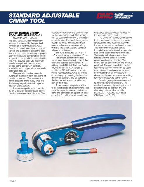
UPPER RANGE CRIMP<br />
TOOL AF8 M22520/1-01<br />
The DMC AF8 qualified to<br />
MIL-<strong>DTL</strong>-22520/1, has virtually limitless<br />
application within the specified<br />
wire range of 12 through 26 AWG.<br />
Over a thousand turret heads or positioners<br />
are available to adapt the tool<br />
frame to your specific military or proprietary<br />
contact/wire combination. The 8<br />
impression crimp, which is standard in<br />
the AF8, assures absolute maximum<br />
tensile strength with almost every<br />
closed barrel contact. In addition,<br />
special indent configurations are available<br />
upon request.<br />
The precision ratchet controls<br />
cycling of the tool in both directions of<br />
handle movement. This assures the<br />
same accurate crimp every time. It’s<br />
like having a quality control inspector<br />
at every work station.<br />
Positive crimp depth is controlled<br />
by an 8 position selector knob conveniently<br />
located on the tool frame. The<br />
operator simply dials the desired step<br />
for the wire being used. This setting<br />
can be secured by use of a locking pin<br />
or safety wire. The carefully engineered<br />
design achieves the absolute maximum<br />
mechanical advantage; along<br />
with the tool’s light weight, operator<br />
fatigue is minimized.<br />
The AF8 measures 9 3 ⁄4″ x 2 1 ⁄2″ x<br />
1 1 ⁄4″ approximately and weighs 15 oz.<br />
For proper operation the tool<br />
frame must be mated with one of the<br />
following optional accessories: a<br />
military head (TH-XXX Part No. Series)<br />
a turret head (TM-XXX series), a<br />
positioner (TP-XXX series), or a universal<br />
head (part No. UH2-5). This is<br />
done simply by orienting the head in<br />
the keyed position, and by tightening<br />
the hex socket screws provided as<br />
part of the head.<br />
A permanent dataplate is affixed<br />
to all turret heads and positioners. This<br />
plate lists specific contact part numbers,<br />
the corresponding position color<br />
code (for 3 position turret heads), and<br />
suggested selector depth settings for<br />
the wire size being used.<br />
The universal head is ideally suited<br />
for lab work and prototype production<br />
applications. This head is attached in<br />
the same manner as explained above.<br />
The selected contact is inserted<br />
through the entry hole on the opposite<br />
side of the tool frame from the head.<br />
The height adjusting screw is then<br />
rotated until the contact is in the<br />
proper position for crimping. The<br />
screw can be secured with the locknut<br />
provided. The wire sizes listed on the<br />
tool frame selector knob can be used<br />
as a reference starting point; however,<br />
some testing will be necessary to<br />
determine the optimum selector setting<br />
for your contact/wire combination.<br />
Periodic gaging is recommended<br />
to insure accurate calibration. This<br />
can be done easily by setting the tool<br />
selector knob to position #4, and<br />
checking indenter closure with<br />
M22520/3-1 “GO/NO-GO” gage<br />
(DMC part no. G125).<br />
PAGE 4<br />
© COPYRIGHT 2003 DANIELS MANUFACTURING CORPORATION