Uncontrolled
Uncontrolled Copy - DTL Connectors
Uncontrolled Copy - DTL Connectors
- No tags were found...

You also want an ePaper? Increase the reach of your titles
YUMPU automatically turns print PDFs into web optimized ePapers that Google loves.
<strong>Uncontrolled</strong> Copy<br />
Supplied by:<br />
Distributed Technology<br />
63 Bluehouse Lane,<br />
Oxted , Surrey. RH8 OAP. England.<br />
Tel : +44 1883 716161<br />
Fax: +44 1883 716865<br />
www.dtl-connectors.co.uk<br />
RADIALL<br />
The Quality Connection
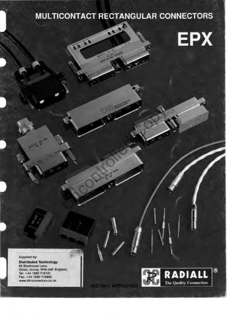
Multicontact connectors<br />
EPX series<br />
Introduction .......... .. .. .... ....... .<br />
Features ....... .... . ... .. .. ......... .<br />
Exploded view of size 2 connector .... . .<br />
Technical characteristics .... . ..... .. .. .<br />
Weights . ...... . .... . ... . . . .. . ..... . . .<br />
How to order ........................ .<br />
Insert module dimensions . . ...... ..... .<br />
Contact arrangements ............... .<br />
EPX size 1<br />
Connector mating guide ... ........... .<br />
Receptacle shells . ... .. ....... . .. .. . . .<br />
Plug shells .. .. . .. .. . . . ... ....... . ... .<br />
Fully mated connector dimensions ..... .<br />
Polarization ...... . .... .......... . . . .. .<br />
Backshelis .. .... . ..... .. ........ . . . . .<br />
Panel cut-outs<br />
3<br />
4<br />
5<br />
6<br />
7<br />
8-11<br />
12<br />
13<br />
14-15<br />
16-18<br />
19-21<br />
21<br />
22<br />
22-24<br />
25<br />
EPX size 2<br />
Connector mating guide . . . . . . . . . . . . . . . 26-27<br />
Receptacle shells . . . . . . . . . . . . . . . . . . . . . 28-30<br />
Plug shells . . . . . . . . . . . . . . . . . . . . . . . . . . . 31-33<br />
Fully mated connector dimensions . . . . . . 34<br />
Polarization . . . . . . . . . . . . . . . . . . . . . . . . . . . 34-35<br />
Backshells . . . . . . . . . . . . . . . . . . . . . . . . . . . 36-38<br />
Panel cut-outs 39<br />
EMI/RFI<br />
Shell fitted with grounding spring fingers 40<br />
Filtered version . . . . . . . . . . . . . . . . . . . . . . . 41<br />
Shell for panel conductive seal . . . . . . . . . . 42<br />
Contacts<br />
Crimp contacts . . . . . . . . . . . . . . . . . . . . . . . 43<br />
PC tail termination contacts . . . . . . . . . . . . . 44<br />
Wire wrap contacts . . .. . ... . .. .. ...... . 45<br />
Coaxial contacts . . . . . . . . . . . . . . . . . . . . . . 46-47<br />
Concentric twin ax contacts ......... . .. . 47<br />
Accessories ............ .. .......... . 48<br />
Tooling . .. ..... . ... . ............. .. . . 49<br />
Termination details<br />
Crimp contacts . . . . . . . . . . . . . . . . . . . . . . . 50<br />
Coaxial contacts . . . . . . . . . . . . . . . . . . . . . . 51 -55<br />
Concentric twinax contacts . . . . . . . . . . . . . 56<br />
Tooling and assembly instructions<br />
Mounting of insert module into the shell . . 57<br />
Mounting of size 1 shell onto panel . . . . . . 58<br />
Insertion and removal of contacts . . . . . . . 58<br />
Mounting of size 2 backshell onto shells 59-62<br />
Mounting of size 1 backshell onto shells 62<br />
Modification of polarization code . . . . . . . . 63<br />
Non standard products<br />
Fiber optic application . . . . . . . . . . . . . . . . . 64<br />
Custom design . . . . . . . . . . . . . . . . . . . . . . . 65<br />
<strong>Uncontrolled</strong> Copy<br />
Index of part numbers . . . . . . . . . . . . . . . . . 66<br />
J<br />
_)<br />
l<br />
/
Multicontact connectors<br />
EPX series<br />
The EPX connector is suitable for applications such as civil and military avionics, aircr~fts,<br />
electronic defence systems.<br />
telecommunications and<br />
Suitable for rack and panel, cable to cable or on front panels replacing circular connectors, the EPX range is available in<br />
two shell sizes.<br />
Space saving and lightweight, EPX has been designed to conform to the UTE-C-93425 HE 510 specification.<br />
The shell being manufactured from an aluminium alloy exhibits both strength and good shielding characteristics. To<br />
improve EMI/RFI characteristics the connector can be fitted with EMI grounding spring fingers and insert modules with<br />
filtered contacts.<br />
The insert modules for pin or socket contacts of the EPX can be mounted into either plug or receptacle shells regardless of<br />
gender and are easily removable with the use of a simple tool. This flexibility allows numerous combinations facilitating any<br />
maintenance work, manufacture of prototype equipment, etc ....<br />
Stacking of connectors is possible and optimizes the packing density of the contact. RADIALL can also upon request<br />
realize any configuration of multiple cavity shells, for specific applications.<br />
The modular concept of the EPX, while having good contact packing density offers the option of separating power<br />
transmission from signal transmission and therefore avoiding crosstalk problems.<br />
EPX uses contacts that are similar to those used in MIL-C-81659 B or ARINC 404 and benefits from rack and panel proven<br />
reliability.<br />
EPX is available in environmental and non-environmental styles with a large range of signal, power, coaxial and triaxial<br />
contacts. Termination styles include crimp, PC tail and wire wrap, front release front removable signal contacts are<br />
available.<br />
Space comparison between a circular connector and an EPX connector :<br />
EPX size 2:<br />
80 contacts size 22<br />
or 60 contacts size 20<br />
<strong>Uncontrolled</strong> Copy<br />
MIL-C-38999 size 21 : 79 contacts size 22<br />
or 41 contacts size 20<br />
15 50 +O ,ZO<br />
-0. 10<br />
(614 ~:~~~)<br />
Mating area = connector area = 14 cm2<br />
Plug area = 15 cm2<br />
Receptacle area = 16 cm2 ~- ___ - - -<br />
Mating area = 50 cm2 -------<br />
November 1994 edition<br />
RADIALL ®<br />
The Quality Conn.:-c ti on<br />
-3-
Multicontact connectors<br />
EPX series<br />
• Compact design provides high packing density and space saving.<br />
• High contact density compared with MIL-C-38999 and other rectangular connectors.<br />
• Low weight.<br />
• Interchangeability of pin and socket insert modules between plug and receptacle<br />
shells.<br />
• Ease of assembly and removable insert modules allowing rapid and easy<br />
maintenance.<br />
• Two sizes of shells : with either 1 or 2 insert modules.<br />
• Mounting styles : rack and panel, cable to cable or front panel mounting (alternative to<br />
circular connectors).<br />
• Protection against mismating provided by polarization keys offering up to 12<br />
positions for size 2 connectors and 36 positions for size 1 connectors.<br />
• Facility to separate power contacts from signal contacts.<br />
• Metal shell and EMI grounding fingers offer EMI/RFI protection.<br />
• Matihg and unmating of connectors by the use of jackscrews.<br />
• Large range of contacts either front or rear removable.<br />
• Use of MIL specification tooling.<br />
<strong>Uncontrolled</strong> Copy<br />
• Large range of shells, insert modules, backshells and accessories.<br />
• Choice of environmental or non-environmental with either filtered or fiber optic<br />
capability.<br />
Items in this catalog are covered by French and foreign Patents and/or Patents pending.<br />
EUR Patent no 0 183 587 - US Patent no 4 659 162<br />
RADIALL ®<br />
The Quality Connection j<br />
-4-
Multicontact connectors<br />
EPX series<br />
<strong>Uncontrolled</strong> Copy<br />
ITJ Shells, male (plug) and female (receptacle)<br />
~ Insert modules environmental or non-environmental<br />
for front or rear removable contacts<br />
[3] Signal contacts size 22, 20, 16, 12. Termination crimp,<br />
PC tail, wire wrap, coaxial size 5, 12 and 15,<br />
concentric twinax size 5 and fiber optic contacts size<br />
12 and 16.<br />
[1) Retention clips for insert module<br />
ffil Jackscrew sleeve with polarising keyway<br />
[QJ Jackscrew<br />
[1] Jacknut with polarising key<br />
[ID Insert module removal tool<br />
RADIALL ®<br />
The Quali ty Connection<br />
-5-
ELECTRICAL CHARACTERISTICS<br />
12<br />
12<br />
14<br />
.075 (1 .9)<br />
.134 (3.4)<br />
23<br />
17<br />
• Insulation resistance (500 V de) :<br />
• Dielectric withstanding voltage at sea level :<br />
> 5000MQ<br />
1500V/50Hz<br />
• EM/ shielding efficiency (page 40) : > 80 dB at 1 GHz<br />
I MECHANICAL CHARACTERISTICS<br />
• Durability: 500 matings<br />
• Shock: 1 shock in each axis<br />
half-sinusoidal I amplitude 50g I duration 11 ms<br />
• Sinusoidal vibration: 10-2000 Hz<br />
acceleration 20 g I 4 H per axis I interruption < 1 fl.S<br />
• Random vibration :<br />
• Salt spray :<br />
1 g 2 /Hz (50/2000Hz) I interruption < 1 fl.S<br />
48, 96 or 500 H depending of shell plating<br />
• Damp heat : 56 days I 95% RH<br />
• Fluid immersion: EN2591 test C15<br />
• Insert module retention :<br />
• Contact retention :<br />
• Mating force :<br />
M/L-T-5624, H-5606, H-7100, L-6081, L-7808<br />
size 22:<br />
size 20:<br />
size 16:<br />
size 12:<br />
size 5:<br />
C-25769, A-8243, COOLANOL 25<br />
shell size 1 :<br />
shell size 2 :<br />
> 40 daN (90 Lbs)<br />
> 4,5 daN (10 Lbs)<br />
> 6,7 daN (15 Lbs)<br />
> 11 daN (25 Lbs)<br />
> 11 daN (25 Lbs)<br />
> 11 daN (25 Lbs)<br />
< 10 daN (22 Lbs)<br />
< 20 daN (42 Lbs)<br />
• Coupling torque (jackscrew): 1.2 Nm (10.4 Lbs/inch)<br />
ENVIRONMENTAL CHARACTERISTICS<br />
• Temperature range : -65 · c to +155 ·c<br />
• Temperature life :<br />
MATERIALS AND PLATING<br />
• Shell:<br />
• Insert module :<br />
• Seal:<br />
• Contact:<br />
• Backshell :<br />
• Screw:<br />
<strong>Uncontrolled</strong> Copy<br />
• Clip·<br />
1000 Hat +155 ·c<br />
aluminum alloy nickel/cadmium<br />
glass filled thermosetting resin<br />
f/uorosilicone elastomer<br />
copper alloy gold over nickel<br />
aluminum alloy nickel/cadmium<br />
stainless steel (48, 96 H salt spray)<br />
aluminum alloy (500 H salt spray)<br />
beryllium copper<br />
RADIALL ®<br />
The Qualit y Connection<br />
-6-
EPX 2 P 17 *<br />
.. REFERENCE<br />
617 900 .·<br />
617911<br />
Open Ty-Rap® backshe/1 (size 2)<br />
617 911 001<br />
617 922 003<br />
<strong>Uncontrolled</strong> Copy<br />
•. 9 (0.32)<br />
16 (0.56)<br />
0<br />
8,4 (0.30)<br />
Size 12<br />
*Polarization and plating to be specified.<br />
RADIALL ®<br />
The Quality Connection<br />
-7-
The modular construction of the<br />
EPX series permits 2 methods of<br />
ordering :<br />
Either by complete part number<br />
(shell, insert modules fitted and<br />
contacts) pages 8 - 9 or by defining<br />
separate components (shell,<br />
insert modules and contacts)<br />
pages 10- 11.<br />
EPX 1 R 11 X1 C<br />
EPX 2 P 17 A N<br />
<strong>Uncontrolled</strong> Copy<br />
-8-
E 40 P Y ························X<br />
E 14 S S E C3 S S X<br />
<strong>Uncontrolled</strong> Copy<br />
The Quahty Conne(' IIOn<br />
-9-
The modular construction of the<br />
EPX series permits 2 methods of<br />
ordering :<br />
Either by complete part number<br />
(shell, insert modules fitted and<br />
contacts) pages 8 - 9 or by defining<br />
separate components (shell,<br />
insert modules and contacts)<br />
pages 10- 11.<br />
EPX 1 R 11 X1 C<br />
EPX 2 P 17 A N<br />
<strong>Uncontrolled</strong> Copy<br />
The Quahfy Connection<br />
-10-
The modular construction of the<br />
EPX series permits 2 methods of<br />
ordering :<br />
Either by complete part number<br />
(shell, :nsert modules fitted and<br />
contacts) pages 8-9 or by defining<br />
separate components (shell,<br />
insert modules and contacts)<br />
pages 10-11 .<br />
EPX E 40 P<br />
*Contact arrangement 0 is available under P/N EPX N 0 (class N without contact type specification)<br />
Contacts (pages 43 to 47), backshells (size 1 page 23 - 24 ; size 2 page 36 to 38) and accessories (page 48)<br />
are to be ordered separately.<br />
<strong>Uncontrolled</strong> Copy<br />
RADIALL ®<br />
The Qualit y Connec tion<br />
-11 -
INSERT MODULE FOR SOCKET CONTACTS<br />
Non environmental<br />
9030<br />
(. 366)<br />
Environmental<br />
9030<br />
(. 366)<br />
.....---.<br />
.L__.I.<br />
-<br />
POLARIZING KEY<br />
12 (.472)<br />
'<br />
INSERT MODULE FOR PIN CONTACTS<br />
Non environmental<br />
POLARIZING KEY<br />
10060<br />
( .417)<br />
10 50<br />
(.059)<br />
10060<br />
( .417)<br />
rr- --<br />
'-- -<br />
POLARIZING KEY<br />
Environmental<br />
-----n<br />
<strong>Uncontrolled</strong> Copy<br />
12 (.472)<br />
'<br />
15050<br />
( .610)<br />
10 90<br />
( .075)<br />
-<br />
,J--1 I_.,_<br />
,l-1<br />
'-- f-<br />
POLARIZING KEY<br />
15050<br />
( .6 tO)<br />
'<br />
12 (.472)<br />
t<br />
12 (.472)<br />
'<br />
RADIALL ®<br />
The Qua lity Conneclion<br />
- 12 -
PIN INSERT MODULES : MATING FACE<br />
Termination styles available are shown in brackets.<br />
40<br />
40 cavities for size 22 signal contacts<br />
30<br />
700000001<br />
boq,poooo'<br />
~oogoooode<br />
LU000000<br />
30 cavities for size 20 signal contacts<br />
28<br />
22 cavities for size 22 signal contacts<br />
6 cavities for size 16 signal contacts<br />
or size 15 coaxial contacts<br />
or size 16 optical contacts<br />
17 '0 4 0000 1 05<br />
110 70 100 0'<br />
01<br />
17<br />
0 0 O.s ·,.0 0 cJ<br />
14 cavities for size 20 signal contacts<br />
3 cavities for size 12 signal contacts<br />
or size 12 coaxial contacts<br />
or size 12 optical contacts<br />
(S,V,W,Y,YA)<br />
(S)<br />
(S,V,W,Y)<br />
(S)<br />
(S)<br />
(S)<br />
(S)<br />
(S)<br />
6<br />
6 cavities for size 12 signal contacts<br />
or size 12 coaxial contacts<br />
or size 12 optical contacts<br />
c 3 [o·Oo]<br />
3 cavities for size 5 coaxial contacts<br />
or size 5 concentric twinax contacts<br />
with cavity reducer:<br />
size 12 signal contacts<br />
size 12 coaxial contacts<br />
l<br />
[ r====' -""=.<br />
0<br />
blanking insert<br />
<strong>Uncontrolled</strong> Copy<br />
(S)<br />
(S)<br />
(S)<br />
(S)<br />
(S)<br />
(S)<br />
14<br />
14 cavities for size 16 signal contacts<br />
or size 15 coaxial contacts<br />
or size 16 optical contacts<br />
(S)<br />
(S)<br />
RADIALL ®<br />
The Qualil y Connec tio n<br />
- 13-
The various components (backshells, plug shells, receptacle shells)<br />
linked by the same coloured line may be coupled together.<br />
Example: backshell617 907 mounts onto plug shell EPX 1 P 11 *as well<br />
as the receptacle shell EPX 1 R 18 *.<br />
Conversely, this plug shell will not mate with this receptacle shell.<br />
*polarization and plating to be specified.<br />
BACKSHELLS<br />
PLUG SHELLS<br />
RECEPTACLE<br />
SHELLS<br />
EPX 1 P 11 *<br />
<strong>Uncontrolled</strong> Copy<br />
EPX 1 B 12 *<br />
BACKSHELLS<br />
_____ ( ]<br />
00 00<br />
RADIALL<br />
The Quality Conneclion<br />
-14-
0 0 0 0<br />
[_______)<br />
617 921 003/004<br />
EPX 1 P 19 * EPX 1 P 21 *<br />
<strong>Uncontrolled</strong> Copy<br />
Thr Qual ily Connec tion<br />
-15-
18. 30 ±0. 10<br />
(.720±.004)<br />
2. 30 ±0. 10<br />
( . 09 1 ± . 004 )<br />
5 10 +0, 15<br />
0<br />
(. 200 \) 006)<br />
ENVIRONMENTAL :<br />
10 (. 394)<br />
NON ENVIRONMENTAL<br />
5 (. 197)<br />
M 3 X 0,5 rf.. 3 10 +0, 10<br />
'f.J • 0<br />
l<br />
18.30 ±0. 10<br />
r<br />
{.720±.004)<br />
r33 . 80 ±0,20<br />
(1.330±.008)<br />
+----5-.-10--+~~.~1~5---------- 1~=----.<br />
(. 200 \) 006) -+-----r'-'---Lol..---------------'l....L----'--',<br />
2 HOLES + 004<br />
(rj;. 122 o· l<br />
I Model supplied with hexagonal nut I<br />
Side or front panel mounting<br />
.. ____,_<br />
<strong>Uncontrolled</strong> Copy<br />
i------i<br />
..., 16 +0, 20<br />
-0, 10<br />
(. 630 ~: ~~~)<br />
ENVIRONMENTAL :<br />
10 (. 394)<br />
NON ENVIRONMENTAL<br />
5 {. 197)<br />
M 3 X 0. 5<br />
8. 10 ±0. 50<br />
(. 319± .020)<br />
0<br />
22 -0.30<br />
0<br />
( . 86 ;- . 0 12)<br />
50, 10<br />
Model supplied with hexagonal nut<br />
Front panel mounting<br />
RADIALL ®<br />
The Qualify Connection<br />
-16-
18. 30 ±0. 10<br />
(. 720± .004) M 3 x o. s--++•<br />
f---- 33' 80 ±0' 20<br />
I (1 .330±.008)<br />
16 +0.20<br />
-0 10<br />
0630~.·~~~:<br />
5 10 +0' 15<br />
' 0<br />
(. 200 + 0006)<br />
1<br />
( .827)<br />
ENVIRONMENTAL<br />
10 (. 394)<br />
NON ENVIRONMENTAL<br />
5 (. 197)<br />
18, 30 ±0. 10<br />
(.720 ±.004)<br />
M 3 X 0 ' 5 ____,-+--_,_.<br />
NON ENVIRONMEN TAL :<br />
5 (. 197)<br />
M 3 X 0, 5<br />
r<br />
33,80<br />
50, 10<br />
( 1. 181<br />
MAX<br />
±0.20 1<br />
(1 .330±.008)<br />
16, 70<br />
( 657)<br />
t<br />
16<br />
•, 70<br />
(. 657)<br />
<strong>Uncontrolled</strong> Copy<br />
r---j-+-----'--'-' 30 ( . 56 3 )<br />
MAX<br />
HEX SOCKET FOR<br />
9/64 ALLEN KEY<br />
~30[5631<br />
12.60 ±0.25 MAX<br />
(.496 ±.0 10)<br />
RADIALL ®<br />
The Qu:dily Conne
18 , 30 ±0 , 10<br />
(. 720±. 004)<br />
MAX PAt~EL<br />
THICKNESS<br />
1. 63 (. 064)<br />
18,70 ±0.20<br />
(.736 ±.008)<br />
5, 10 +~, 1 5<br />
(. 200 + 0006)<br />
ENVIRONMENTAL :<br />
10 (. 394)<br />
NON ENVIRONMENTAL<br />
5 (. 197)<br />
4 HOLES M 2 x 0,40<br />
C'SUNK go•<br />
------<br />
HEX SOCKET FOR ~.30 1.563)<br />
9/64 ALLEN KEY MAX<br />
<strong>Uncontrolled</strong> Copy<br />
Model supplied with knurled slotted screws<br />
Jackscrew is provided with a hex socket<br />
and slot for tightening with a key or<br />
screwdriver<br />
* Polarization and plating to be specified<br />
RADIALL ®<br />
The Quality Connection<br />
-18-
50. 10 (.ZOO) MAX<br />
* Polarization and plating to be specified<br />
ENVIRONMENTAL :<br />
10 (. 394)<br />
NON ENVIRONMENTAL<br />
5 (. 197)<br />
¢ 7 --~----+--•<br />
[¢ .Z75)<br />
HEX SOCKET<br />
IT,JO<br />
FOR<br />
9/64 ALLEN KEY<br />
1.563)<br />
ld!bl<br />
MAX<br />
10.65 +~, 10<br />
( . 4 19 \) 004 )<br />
* Polarization and plating<br />
to be specified<br />
ENVIRONMENTAL :<br />
10 (. 394)<br />
NON ENVIRONMENTAL<br />
5 (. 197)<br />
r--.- 5. 10<br />
10.65 +~.<br />
10<br />
(. 4 19 + 0004)<br />
M 3 X 0, 5<br />
+0 15<br />
( zoo + 0<br />
50 1 0 ( . ZOO) MAX<br />
~:<br />
r JO [1181)d<br />
0· _ --<br />
006)<br />
8 10.<br />
MAX ( .3 19 ±.<br />
h=l If . ~<br />
@I<br />
I<br />
Nl<br />
""'<br />
l<br />
11'-,<br />
I--'<br />
......<br />
M 3 X 0. 5<br />
<strong>Uncontrolled</strong> Copy<br />
=x<br />
..................<br />
16. 70<br />
(.657)<br />
t<br />
0,50<br />
OZO)<br />
( .614<br />
TOTAL PLAY :<br />
¢ 0. 75 ±0. 05<br />
[¢ 030± OOZ)<br />
3~A~ 563)<br />
bJ14.<br />
~-~<br />
'-..."-..<br />
'-JI<br />
~~<br />
"'<br />
"" '"-<br />
PANEL<br />
THICKNESS<br />
15 60 +O.<br />
. -0.<br />
(. 614 + 008)<br />
-.004<br />
0<br />
z -0. 10<br />
(.079 _0004<br />
zo<br />
10<br />
RADIALL ®<br />
The Quality Connectio n<br />
- 19-
* Polarisation and plating to be specified<br />
I Model supplied with hexagonal nut I<br />
Front panel mounting<br />
50. 10 ( .200) MAX<br />
[ill<br />
11 .6541<br />
M 3 X 0. 5<br />
ENVIRONMENTAL :<br />
10 (. 394)<br />
NON ENVIRONMENTAL<br />
5 (. 197) M 3 X 0, 5<br />
5 10 +0. 15<br />
c-- . 0 - -<br />
10.65 +~, 10<br />
(. 4 19 + 6004)<br />
(.ZOO \)006)<br />
* Polarisation and plating to be specified<br />
NON ENVIRONMENTAL<br />
5 (. 197)<br />
M 3 X 0, 5<br />
5 10 +0. 15<br />
. 0 -<br />
'- ( . zoo + 6<br />
10 65 +O. 10<br />
. 0<br />
( . 4 19 + 6 004)<br />
I<br />
F1<br />
~~<br />
f--..1<br />
r d<br />
30 ( 1 181)<br />
MAX<br />
8.10<br />
I<br />
50. 10 (.ZOO) MAX<br />
~:<br />
J1<br />
!=<br />
0.50<br />
±<br />
(. 319±. 020)<br />
16. 70<br />
(. 657)<br />
t<br />
M 3 X 0. 5<br />
i--30(1.181)l 12,60 ±O,Z5<br />
MAX (.496±. 010)<br />
IU II u 60<br />
<strong>Uncontrolled</strong> Copy<br />
~<br />
006)<br />
tBi n ll<br />
I<br />
1--'<br />
....... !:n:<br />
16 , 70<br />
(.657)<br />
t .._ ........,<br />
~~<br />
•O zo<br />
~ -0.10<br />
( . 6 14 ~ : ~~~)<br />
15<br />
60 +0.20<br />
-0. 10<br />
( 614 ~: ~~~)<br />
RADIALL ®<br />
The Qualify Connection<br />
-20-
4 HOLES M 2 x 0,40<br />
C'SUNK 90'<br />
ENVIRONMENTAL :<br />
10 (. 394)<br />
NON ENV IRONMENTAL<br />
5 (. 197)<br />
50 10 ( . 200) MAX<br />
.•..<br />
.·.· .. ·.· .. · .... ·.· ..<br />
F'~rfNllmb~r ) ·. ····<br />
~~XtB~iH •>·<br />
* Polarization and plating to be specified<br />
Model supplied with knurled slotted screws<br />
Jackscrew is provided with a hex socket and<br />
slot for tightening with a key or screwdriver<br />
14 ,30 (.563)<br />
r--- --r- MAX<br />
10 65 +O, 10<br />
0<br />
(419\)004)<br />
---+--+--- M 3 X 0 ' 5<br />
Visual fully mated "indicator"<br />
<strong>Uncontrolled</strong> Copy<br />
I<br />
t---<br />
23,65 ±0.25<br />
(.931 ±.010)<br />
._______,._.___~J ---'---~<br />
I<br />
I<br />
15 60 +<br />
0· 20<br />
' -0. 10<br />
--r--<br />
(. 614 ~: ~~~<br />
Front panel mounting only<br />
(except variant 31)<br />
RADIALL ®<br />
The Qualil y Conne
The two polarizing keys fitted to extremities of the size 1 shell can each take 6 positions. This enables up to 36 different<br />
codes.<br />
The polarization code corresponds to a letter or a number determined by the indicator on the edge of the polarizing<br />
keys. This code is carried over into the part number of the shell or complete connector in the column "polarization<br />
code".<br />
Example : in the drawing below, the position of the polarizing keys is N2 for the plug shell and N2 for the receptacle<br />
shell. Tt)is polarization code allows these two shells to be mated.<br />
To change the position of the polarizing keys see page 58.<br />
PLUG SHELL<br />
RECEPTACLE SHELL<br />
.------- h:ll<br />
32,50<br />
280:1~<br />
39L r<br />
LJ:<br />
( 1 . 535) 30 2' 50<br />
[0981<br />
2 HOLES<br />
¢ X<br />
~______J~<br />
50<br />
( 1. 969)<br />
¢ 12<br />
(. 472)<br />
2.80<br />
[~ ::J c<br />
<strong>Uncontrolled</strong> Copy<br />
6<br />
( .236)<br />
1 5,60<br />
( .614)<br />
Fitting the backshell, see page 66.<br />
cadmium/nickel under plate 617 907 5.1<br />
® Trade Mark ofThomas & Betts Corp.<br />
For other platings, consult Radiall.<br />
RADIALL ®<br />
The Quality Connection<br />
-22-
13 (. 512)<br />
ON FLATS<br />
50 MAX<br />
( 1. 969)<br />
30<br />
( 1. 18 1)<br />
2 HOLES<br />
¢ X<br />
__l___L_______l _<br />
34 '30<br />
(1 . 350) 2,80<br />
(. 110)<br />
50<br />
( 1. 969 )<br />
35 50<br />
(1 . 398)<br />
2<br />
(.079)<br />
0 0 0<br />
2. 50<br />
( .098 )<br />
______.J=4<br />
_ ¢ 10<br />
(. 394)<br />
5 (. 1 97)<br />
15 . 60<br />
1-4-------t-( . 6 14 )<br />
Fitting the backshell, see page 66.<br />
· < < Partillirriber < x Oia<br />
9~1M iJ fulrisR~ ~ Ji)1erpiCJ.le 61-rs66 3.1<br />
cadmium/nickel underplate 617 908 5.1<br />
For other platings, consult Radiall.<br />
<strong>Uncontrolled</strong> Copy<br />
l<br />
Fitting the backshell, see page 66.<br />
2 HOLES<br />
¢ X<br />
4 1~---<br />
:~<br />
50<br />
( 1. 969)<br />
L=l<br />
.. I<br />
15 . 60<br />
( 614)<br />
42<br />
cadmium olive drab<br />
617 921 003<br />
ci drl1rum/nickel underpiaie. 617 921602<br />
cadmium olive drab 617 921 001<br />
For other platings, consult Radiall.<br />
3.1<br />
5.1<br />
RADIALL ®<br />
The Qualit y Connection<br />
- 23-
34<br />
(1.338) 5(.197)<br />
2<br />
( .079)<br />
0 0 0<br />
34.30 2 80 J<br />
'I<br />
I~ 50 y I<br />
2 HOLES ~II .969)-----2:J<br />
¢ 5. 20(,205)<br />
2 HOLES<br />
M 2 X 0,40<br />
1<br />
16. 10 ( .634) MAX<br />
28,50<br />
(1 .122)<br />
L_<br />
L 49,60_j<br />
S-u-ita-b-le-fo-r -sh-el-l s-ty-le-s-23_ a_n_d -31-. ---,~<br />
48<br />
( 1. 89 0) 4 30<br />
(. 169)<br />
( 1. 953)<br />
11' 35<br />
(. 447)<br />
4 VIS M 2 x<br />
y<br />
4VIS<br />
M 2 X 0, 40<br />
<strong>Uncontrolled</strong> Copy<br />
16 .20 ~<br />
(. 638)<br />
I<br />
- -<br />
I<br />
Plating<br />
'\<br />
l<br />
This model permits attachment of cable braids onto the finger strip of the backshell using heatshrink<br />
solder sleeves (supplied with the backs hells).<br />
For other platings, consult Radial!.<br />
RADIALL ®<br />
The Qualify Connection<br />
- 24-
FIXED MOUNTING ON FRONT OF PANEL (except shell variant 13 and 31)<br />
B<br />
f<br />
30. 10 MIN<br />
~-----.>-----~ A<br />
( 1 . 185 ) 2<br />
+ R.2 MAX<br />
C0 4 7 2 9M~<br />
....._------,.---------.J<br />
14.40 MIN<br />
(. 567) ( 1. 653)<br />
HOLES ¢ 3. 10 ~0 · 10 ( . 122 ~ · 004 )<br />
I fit I ¢ 0' 10 ( . 004) @ I A I B I<br />
FLOAT MOUNTING ON FRONT OF PANEL (shell variant 13 only)<br />
B<br />
t<br />
+----<br />
15 . 30 MIN<br />
(.602 )<br />
31 MIN<br />
( 1 .220)<br />
~----~____,A<br />
R.Z MAX<br />
R. 079 MAX)<br />
42<br />
( 1. 653) _ ___,<br />
SIDE MOUNTING FOR RECEPTACLE SHELL WITHOUT FLANGE (shell variant 12)<br />
*-<br />
-,---t___,___: 2 HOLES ¢ 7 ±0 . 05 ( . 276 ±. 002 )<br />
I fit I ¢ 0' 10 ( . 004) @ I A I B I<br />
32. 50±0. 10 2 HOLES ¢ 3, 10 +0. 10 (. 122 +. 004)<br />
i :, fi_L ZBO±<br />
004<br />
\J[ OR M3 ~ 0, 5 THREA~<br />
-¥.':<br />
'<br />
" '<br />
I 1 1 I<br />
'- .::. -'1 l~o. -'<br />
-+------·-------------"<br />
15.80 MIN<br />
(. 622)<br />
<strong>Uncontrolled</strong> Copy<br />
FIXED MOUNTING ON REAR OF PANEL (shell variant 31 only) :-Consult Radiall<br />
The Quality Connection<br />
-25-
The various components (backshells, plug shells, receptacle shells) linked<br />
by a line may be coupled together.<br />
Example : plug shell EPX 2 P 19 * will only mate with receptacle shell<br />
EPX 2 R 18 *.<br />
*Polarization and plating to be specified.<br />
BACKSHELLS<br />
-<br />
PLUG SHELLS<br />
RECEPTACLE SHELLS<br />
~L----E-PX-~~1-2_*~~<br />
<strong>Uncontrolled</strong> Copy<br />
EPX 2 B 12 *<br />
L-----L....r"\'--__ ?<br />
BACKSHELLS<br />
RADIALL ®<br />
The Quality Connectio n<br />
-26-
I<br />
EPX 2 B 14 * I EPX 2 R 18 *<br />
'L..------,<br />
<strong>Uncontrolled</strong> Copy<br />
(<br />
I<br />
RADIALL<br />
The Quality Connection<br />
-27-
18, 30 ±0, 10<br />
(.720 ± 004)<br />
5. 10 ~0, 15<br />
1,=75 ,80 ±0.20 ~<br />
(2.984 ±.008)<br />
74 ±0, 10<br />
( 2 . 9 13 ± . 004 )<br />
Fixed by two clearance holes<br />
Rack or cable version<br />
2. 55 ±0, 10<br />
( . 100 ± . 004)<br />
NON ENVIRONMENTAL<br />
5 ( 197)<br />
4 HOLES<br />
¢3, 1 ~0 , 10<br />
( ¢ . 1 22 ~ 004 )<br />
················· P~ ifNJM!j;W •••···············<br />
* Polarization and plating to be<br />
specified<br />
18 ,30 ±0. 10<br />
(. 720 ±. 004)<br />
5. lO ;o. 15<br />
-<br />
( . zoo ~. 006)<br />
NON ENVIRONMEN TAL<br />
5 ( 197)<br />
2 HOLES<br />
¢3, 1 ~0, 10<br />
(¢ . 122 ~ 004 )<br />
Part Number<br />
EPX2_B 12 *<br />
~<br />
* Polarization and p lating t? be<br />
specified<br />
I<br />
7 4 ±O · 25 .-------~~ -~ ENVIRONMENTAL<br />
(2.913 ±.010)<br />
13.2281<br />
M 5 X 0,8<br />
r--------- 88 (3 .464) ------~<br />
MAX<br />
r<br />
_______ (75 , 80 ±0' 20 ------~-.ll<br />
2.984 ±.008)<br />
~~<br />
--u;;;;;;;;;;;v \ I<br />
I~ 74 ±0,25 ___ ___,:-.li~ENTAL<br />
~8~ ~ ~ '---" '---"<br />
1\. I<br />
~<br />
00<br />
I<br />
J<br />
10 (. 394)<br />
<strong>Uncontrolled</strong> Copy<br />
---+<br />
16 10 +O,ZO<br />
' -0, 10<br />
( . 6 30 ~ : ~~~)<br />
(2.913 ±.010) 10 (.394)<br />
I<br />
I<br />
13. zz8l<br />
88 (3.464)<br />
MAX<br />
M 5 X 0 8<br />
~~<br />
~<br />
Fixed by two clearance holes<br />
Rack or cable version<br />
I<br />
\<br />
\<br />
.,<br />
1<br />
I<br />
I<br />
0<br />
22 -0 30<br />
0 .<br />
(.866t<br />
-.012)<br />
20<br />
16, 10 ~~·<br />
10<br />
( . 630 ~. 0 08<br />
.004)<br />
RADIALL ®<br />
Th
18,30 ±0, 10<br />
( . 7 20 ± . 004)<br />
5. 10 ~0, 15<br />
-<br />
( .200 ~ 006)<br />
NON ENVIRONMENTAL<br />
5 (. 197)<br />
2 HOLES<br />
I<br />
______<br />
.--<br />
r<br />
75. 80 ±0. 20 --------~1 Fixed<br />
(2. 984 ± . 008)<br />
I<br />
I~<br />
M 3 X 0, 5<br />
~<br />
~~ '--"<br />
18 , 30 ±0 . 10<br />
(. 720 ± 0 004)<br />
16<br />
(. 630)<br />
t<br />
))}<br />
plating to<br />
5 10 +0, 15<br />
. 0 -<br />
( . 200 ~ . 006)<br />
NON ENVIRONMENTAL<br />
5 (. 197)<br />
2 HOLES<br />
¢ 3 . 1 ;o. 10<br />
l<br />
~<br />
~~<br />
16=» \ I :=1<br />
I<br />
by 2 threaded holes<br />
Rack or cable version<br />
ENVIRONMENT A L<br />
10 (. 394)<br />
74 ±0. 25 -------~=~1 16 10 •0. zo<br />
(2 .913 ±.010) . -0. 10<br />
I<br />
I<br />
I<br />
~ '--"<br />
I<br />
[][]<br />
13.2281<br />
88 (3 .464)<br />
MAX<br />
------- 75,80 ±0.20<br />
(2 . 984 ± . 008)<br />
1<br />
~~<br />
l==<br />
I<br />
~,<br />
M 5 X 0 8<br />
~~<br />
<strong>Uncontrolled</strong> Copy<br />
74 ~Z5<br />
2 .913 ±.010<br />
-<br />
I<br />
-<br />
I<br />
( 630 +.00 8 l<br />
- .004<br />
E NV IRONMENT AL<br />
10 (. 394)<br />
\ I<br />
I<br />
•<br />
22<br />
( .866t<br />
0<br />
-0.30<br />
0<br />
-.0 12)<br />
N.B. : for a recept acle shell<br />
without flange fix ed by 2<br />
threaded holes, us e the P/N<br />
EPX 2 R 14 *<br />
Cable version<br />
HEX SOCKET FOR<br />
9/64 ALLEN KEY<br />
(¢. 122 ; 004)<br />
* Polarization and plating to be<br />
specified<br />
~------88 (3.464)<br />
MAX<br />
16 10 +<br />
0· 20<br />
. -0, 10<br />
(.630 ~ ~~~)<br />
RADIALL ®<br />
The Qual it y Connecti on<br />
-29-
18, 30 ±0, 10<br />
( . 720 ±. 004)<br />
75.80 ±0.20~<br />
1,=(2.984 ±.008)<br />
7 4 ±0 • 10 * Polarization and plating to be<br />
(2 . 9 13 ±. 004 l specified<br />
5<br />
10 +0 . 15<br />
. 0<br />
~w z. 55 ±0. 10<br />
(. 200 ~. 006) +----r----'rlib~<br />
(. 100 ±.004)<br />
NON ENVIRONMENTAL<br />
5 (. 197)<br />
4 HOLES<br />
¢3, 1 ~0. 10<br />
(¢ . 122 ~.004)<br />
4 HOLES M 2 x 0.40<br />
C'SUNK 90 •<br />
74 ±0,25<br />
~---- (2 . 913 ±.010)<br />
M 5 X 0, 8<br />
88 (3.464) -----~<br />
~------ MAX<br />
ENVIRONMENTAL<br />
10 (. 394)<br />
<strong>Uncontrolled</strong> Copy<br />
\_<br />
•<br />
_j[_<br />
_j)_<br />
J<br />
16 10 +0.20<br />
' -0, 10<br />
( . 6 30 ~ : ~~~)<br />
RADIALL ®<br />
Th£" Qualit y Connection<br />
-30-
Cable version<br />
15 60 +<br />
0· 20<br />
. -0 . 10<br />
[. 6 14 ~ : ~~~}<br />
2 HOLES<br />
¢3. 1 ~0. 10<br />
M 5 X 0.8 [¢. 122 ~ . 004}<br />
NON ENVIRONMENTAL<br />
5 [. 197)<br />
-<br />
r<br />
(.6·lO)<br />
l<br />
+0. 10<br />
10.65 0<br />
{.419 ~.004}<br />
15 60 +<br />
0· 20<br />
. -0. 10<br />
[ . 6 14 ~ : ~~~}<br />
I<br />
NON ENVIRONMENTAL<br />
4. 8 (. 189)<br />
74 +0 - . 25<br />
[2.9 13 ±.010)<br />
•<br />
~<br />
r~J[=¢~<br />
'---<br />
\<br />
* Polarization and plating to be<br />
specified<br />
HEX SOCKET FOR<br />
ENVIRON MENTAL ALLEN KEY 9/64<br />
10 [ .394}<br />
I<br />
5 10 +0, 15<br />
. 0 -<br />
[ . zoo ~ . 006)<br />
~------ 89 (3. 504) --------~<br />
MAX<br />
[][]<br />
13. 228~------.-j<br />
r<br />
<strong>Uncontrolled</strong> Copy<br />
74 +0 - . 25<br />
(2.913 ±.010)<br />
Rack version<br />
Z FLOATING EYELETS<br />
¢ 3 . 1 ~o. 10 (¢. 122 ~ .004)<br />
TOT AL PLAY :<br />
¢ 0.75±0.05 (¢.030± .002<br />
ENVIRONMENTAL<br />
9. 8 {. 386)<br />
* Polarization and plating to be<br />
specified<br />
10.50 ±0.25<br />
(.413 ±.010)<br />
-<br />
]<br />
~<br />
r~Jl=¢~<br />
u<br />
\<br />
[<br />
15.95 ±0. 15<br />
( 628 ±. 006)<br />
I \<br />
~<br />
RADIALL ®<br />
The Qua lit y Connecti on<br />
- 31 -
15 60 +<br />
0· 20<br />
' -0, 10<br />
(.614 ~ : ~~~)<br />
1-4--------88 {3 . 464 ) ______ ~<br />
MAX<br />
00<br />
13.2281<br />
r<br />
2 HOLES<br />
¢3, 1 ~0, 10<br />
(¢. 122 ; .004)<br />
Rack version<br />
* Polarization and plating to be<br />
specified<br />
5, 10 ~ 0 , 15<br />
( .ZOO 0006)<br />
-+---+--.--__J__<br />
10, 65 ~ 0 ·<br />
10<br />
(. 419 ~ . 004)<br />
<strong>Uncontrolled</strong> Copy<br />
I .\<br />
If If<br />
Rack version<br />
2 FLOATING DEVICE M 3 x 0, 5<br />
THREAD DEEP:7. 50 (.295)<br />
TOTAL PLAY:<br />
¢ 0,75±0 , 05 {¢ .030±.002)<br />
* Polarization and plating to be<br />
specified<br />
NON ENVIRON MET AL<br />
10 ' 40 (. 409)<br />
74 ±0 . 25<br />
(2 .913 ±.0 10)<br />
ENV IRONMENTAL<br />
15' 40 ( . 606)<br />
COMPR E SSIO~<br />
2. 50 MAX<br />
(. 100 MAX<br />
10,50±0. 25<br />
(.413 ±.0 10)<br />
0, 30 ±0, 10<br />
(.012±.00(<br />
RADIALL ®<br />
T h ~ Quality Connectio n<br />
-32-
15 . 60 ~~ : ~~<br />
( . 6 14 ~ : ~~~)<br />
~------ 88 (3.464)--- -------l<br />
MAX<br />
[][]<br />
13 .228 I M 5 X 0.8<br />
r<br />
NON ENVIRONME N T AL 74 +0 - ' 25<br />
(2 . 9 13 ±. 0 10)<br />
5 (. 197)<br />
5. 10 ;o ' 15<br />
-<br />
...n=n_<br />
06)<br />
(. 200 6 °<br />
10 65 +O ' 10<br />
' 0<br />
(. 419 ; . 004)<br />
5 60 +0,20<br />
' - 0. 10<br />
. 614 ~: ~~~)<br />
-:--<br />
r_L<br />
NtJJ[:6~<br />
R W<br />
B<br />
M 5 X 0, 8<br />
? s<br />
<strong>Uncontrolled</strong> Copy<br />
2 HOLES<br />
¢3. 1 ~0 , 10<br />
004<br />
1¢ . 122 ~ -<br />
)<br />
Cable version<br />
* Polarization and plating to be<br />
specified<br />
ENVIRON MENTAL<br />
10 (. 394)<br />
Q<br />
I<br />
13<br />
(. 512)<br />
2 HOLES<br />
\<br />
L..::..J<br />
¢3 . 1~0. 1 0<br />
1¢ . 122 ~<br />
004 )<br />
4 HOLES M 2 x 0,40<br />
C'SUNK go •<br />
For mounting of 617 922 002<br />
Ty-Rap backshell<br />
74 ±0,25<br />
NON ENVI RONMENT AL F(Z.913 ±.010)<br />
5 (. 197)<br />
.--- -<br />
16<br />
( .630 )<br />
HEX SOCKET FOR<br />
ALLEN KEY 9/.6 4<br />
* Polarization and plating to be<br />
specified<br />
EN VI RONMENTAL<br />
10 (. 39 4)<br />
I<br />
10 65 +O.<br />
' 0<br />
10<br />
D()()()()()()()XX)(l<br />
OCXXXXXXXXXXXXXXXXj<br />
5 10 +0. 15<br />
' 0<br />
( . 4 19 ; . 004) Visual fully mated indicator ( . zoo ~. 006)<br />
RADIALL ®<br />
The Quality Connectio n<br />
-33-
Rear panel mounting<br />
Front panel mounting<br />
13,35 ±0,25<br />
(. 526 ±. 0 10)<br />
L_<br />
The polarization of size 2 shells is realised by a central polarizing key provided with 6 flats.<br />
I<br />
23,65 ±0,25<br />
(.931 ±.010)<br />
_j<br />
The polarizing indicator is a lug on the jacknut and jackscrew sleeve with a keyway. This indicator shows the<br />
polarization co·de .<br />
This code represented by a letter, is marked on the side of the shell.<br />
For the polarization code, the indicator is aligned to the corner of the polarizing Hex (A, B, C, D, E, F codes) or to a<br />
flat (N, R, W, X, Y, Z codes) .<br />
<strong>Uncontrolled</strong> Copy<br />
The code is carried over into the part number of the shell or the complete connector in the column "polarization code".<br />
To change the polarizing position please see page 63.<br />
Polarizing key P/N page 48.<br />
RADIALL ®<br />
The Qua li ty Conneclion I<br />
-34-
Polarization code is marked on the shell.<br />
A, B, C, D, E, F polarization code<br />
The polarizing indicator is aligned to the corner of polarizing hex.<br />
E<br />
polarizing hex.<br />
PLUG SHELL 0<br />
B<br />
A<br />
0<br />
c<br />
This position for polarizing<br />
allows mating of the two shells.<br />
In this example, polarization<br />
position is F.<br />
polarizing indicator<br />
RECEPTACLE 0<br />
SHELL<br />
polarizing indicator<br />
N, R, W, X, Y, Z polarization code<br />
The polarizing indicator is aligned to the flat of polarizing hex.<br />
PLUG SHELL 0<br />
B<br />
B<br />
B polarizing hex.<br />
E<br />
c<br />
D<br />
polarizing hex.<br />
<strong>Uncontrolled</strong> Copy<br />
A<br />
0<br />
0<br />
polarizing indicator<br />
This position for polarizing<br />
allows mating of the two shells.<br />
In this example, polarization<br />
position is N.<br />
0<br />
v<br />
polarizing indicator<br />
I RADIALL ®<br />
The Qualit y Connecti on<br />
- 35-
cl·;----(2-.9-i_3) _-_----------~---JI<br />
34,50 ~~--<br />
0--------~ 0 ~ 1<br />
( 1. 358)<br />
I .t==Lc::-======::::=::::J.....~~rc::=::T"l"""L-=========jj<br />
( .051)<br />
35 MAX<br />
( 1. 378) 26.50<br />
( 1. 043)<br />
r----- 63,50<br />
(2 . 500 ) __ _.-..J<br />
(2.913) 74 _____<br />
6, 50<br />
(. 256)<br />
<strong>Uncontrolled</strong> Copy<br />
15,60<br />
(. 614)<br />
platings, consult Radiall.<br />
6<br />
(. 236)<br />
1' 30<br />
( .051 )<br />
-- 2 CAVITIES FOR<br />
SEPARATION OF CIRCUITS<br />
015, 60<br />
(. 614)<br />
Fitting the backshell , see page 59.<br />
For other pi a r Jngs, consul Radiall.<br />
RADIALL ®<br />
The Qualily Connectio n<br />
-36-
46 MAX<br />
( 1.811)<br />
26.50<br />
( 1.043)<br />
1' 30<br />
( .051)<br />
I<br />
48.5 MAX<br />
¢ 10<br />
(. 394)<br />
74<br />
(2 . 913)<br />
Z CAVITIES FOR<br />
SEPARATION OF CIRCUITS<br />
(Z . 9 13 l .------:.---r--__.__. - - I r-- - - I<br />
26. so I I I I<br />
( 1. 043)<br />
15.60<br />
( .6 14)<br />
Fitting the backs hell, see page 60 .<br />
. . ... ... . -.·.-.-....<br />
.. )< Partnultlbel- >>><br />
>_._ y~df1lilJ&tbi~ k~' ••wF~ e fP 1 •~~~ •••••••••••• < s h. 9o2 •.>•····· ·.<br />
For other platings, consult Radiall.<br />
2,80<br />
(. 110)<br />
F-<br />
<strong>Uncontrolled</strong> Copy<br />
7<br />
(. 276)<br />
¢ 15.60<br />
( 614)<br />
1' 30<br />
(. 051)<br />
¢ 10<br />
(. 394)<br />
Z CAVITIES FOR<br />
'--- SEPARATION OF CIRCUITS<br />
015,60<br />
(. 614)<br />
Fitting the backshell, see page 61.<br />
Plating<br />
Part number<br />
cadmium/nickel underplate 617 903<br />
For other platings, consult Radiall.<br />
RADIALL ®<br />
The Qualily Connection<br />
-37-
t5C<br />
29<br />
( l . 161)<br />
t=J<br />
1. 30<br />
(.051)<br />
16. 10<br />
(. 63 4) MAX<br />
28 .50<br />
(1. 122)<br />
+<br />
-.,.......<br />
0<br />
r--<br />
0 0<br />
"<br />
~ ~<br />
74 00<br />
(2. 913)<br />
2<br />
( .079)<br />
0 0 0 0 0<br />
r-. r-.<br />
L--...J<br />
](Q)[<br />
87 50<br />
4,30 ( 3 .445)<br />
(. 169)<br />
" " " " " " " "<br />
5 (. 1 97)<br />
<strong>Uncontrolled</strong> Copy<br />
~ ~ ~ ~ ~ ~ ~ ~<br />
~<br />
· 0<br />
r---<br />
-<br />
15.60<br />
(. 614)<br />
Fitting the backshell, see page 62.<br />
15,30<br />
(.602) ~-<br />
0<br />
I Suitable for shell styles 22 and 32.<br />
4 VIS M 2 x<br />
This model permits attachment of cable braids onto the finger strip of the backshell using heatshrink<br />
solder sleeves (supplied with the backs hells}.<br />
For other platings, consult Radial I.<br />
RADIALL ®<br />
The Quality Co nnection<br />
- 38 -
FIXED MOUNTING ON FRONT OF PANEL (except shell variant 13 and 17)<br />
16.40 MIN<br />
(. 646 )<br />
76,20 MIN<br />
~--------~------------~~ A<br />
(3 .000)<br />
2 HOLES¢ 3. 10 ~ 0 . 10 ( . 1 22 ~ · 004)<br />
R . 1 . 8 ( 0 7 1 ) MAX<br />
OR M3 x 0, 5 THREAD<br />
I ~ I ¢ 0' 1 0 ( . 004 ) (@ I A I 8 I<br />
82<br />
(3.228 )<br />
FLOAT MOUNTING ON FRONT OF PANEL (shell variant 13 and 17 only)<br />
77 MIN<br />
A f--..-11-----------------------~<br />
(3. 03 1)<br />
17,20 MIN<br />
(. 677)<br />
R. 1. 8 (. 071) MAX<br />
82<br />
(3 . 228)<br />
2 HOLES ¢ 3, 10 ~0. 10 ( 122; . 004)<br />
OR M3 x 0.5 THREAD FOR<br />
FLOAT MOUNTING ON REAR<br />
OR FRONT PANEL<br />
<strong>Uncontrolled</strong> Copy<br />
2 HOLES ¢ 3, 10 ~0 · 10 (. 122 ~ · 004 )<br />
FOR FLOAT MOUNT ING SPRING<br />
LOADED ON REAR PANEL<br />
I~ I ¢ 0. 10 (@ I A I 8<br />
SIDE MOUNTING FOR RECEPTACLE SHELL WITHOUT FLANGE (shell variant 12 and 32 only)<br />
74±0, 10<br />
(2. 9 13±. 004)<br />
cr- -;- ~ ;<br />
15,80 MIN<br />
(. 622 )<br />
: - . - - - - - - - - - - - .:- - ' I 2 HOLES ¢ 3' 10 ~0' 10 (. 122 ~. 004 )<br />
The Qualit y Connection<br />
-39-
A grounding spring fingers fitted to each plug shell cavity provides excellent EMI/RFI integrity between<br />
mated plugs and receptacles.<br />
This configuration is available for both plug shell sizes and all shell variants.<br />
! 111111 1 1111 1 11 1111 1 1 1 1 111111~ ~"'"""'"···' '"·~lllllllllllllllllllllllllr~~ ~~~~~~~ ~~~~~~~~~~~~~~ ~~~r<br />
fmgers<br />
CHARACTERISTICS<br />
Shielding effectiveness :<br />
Electrical continuity between shell :<br />
Durability :<br />
Grounding spring fingers material :<br />
ATTENUATION CURVE<br />
* Shell variant, polarization and plating to be specified<br />
0<br />
m<br />
-10<br />
~<br />
C/) -20<br />
C/)<br />
w<br />
z<br />
-30<br />
w<br />
> -40<br />
i=<br />
u<br />
w<br />
u.. -50<br />
u..<br />
w -60<br />
C)<br />
z<br />
-70<br />
0<br />
_J<br />
w -80<br />
I<br />
C/)<br />
___ ,..<br />
-90 ~ r-<br />
-100<br />
.5<br />
> 80 dB at 1 GHz<br />
< 1 mQ<br />
500 matings<br />
Beryllium copper, tin over nickel underplate<br />
<strong>Uncontrolled</strong> Copy<br />
____..-"'<br />
v<br />
/\ r., v<br />
_,<br />
FREQUENCY (GHz)<br />
1<br />
10<br />
HOW TO ORDER<br />
Version identified by the letter "H " in the column "shell type" (page 8 or 1 0).<br />
RADIALL ®<br />
The- Quality Connect inn<br />
-40-
Filtered EPX connectors provide a convenient method of preventing transmission of unwanted electromagnetic<br />
interference through input/output cables.<br />
To realise this function, RADIALL use and has a special expertise in two technologies :<br />
- Tubular filters : assembly of inductive/capacitive components on the contact,<br />
- Array filters : assembly of inductive/capacitive components in array.<br />
CHARACTERISTICS<br />
Operating voltage :<br />
Dielectric withstanding voltage :<br />
Insulation resistance :<br />
Temperature range :<br />
Electronic structure :<br />
Tubular<br />
200V<br />
500V<br />
> 10 000 MQ (200 V cc)<br />
-55°C I +125°C<br />
Pi<br />
Others structures available on request. Consult Radiall.<br />
TYPICAL ATTENUATION CURVES FOR DIFFERENT CAPACITANCE VALUES<br />
0<br />
-10<br />
-20! ........_<br />
6 -40<br />
~<br />
~ - 50<br />
w<br />
~ - 60 '<br />
-70 I<br />
-80<br />
1<br />
0<br />
- 10<br />
-20<br />
I<br />
m -30<br />
m - 3o<br />
"'-<br />
"'-<br />
z<br />
0 -40<br />
I<br />
~<br />
::><br />
z -50<br />
w I<br />
~ -60<br />
I<br />
-70;<br />
TUBULAR FILTERS<br />
~ r--- :-.<br />
1'---. 'r--<br />
I<br />
"~<br />
I<br />
I<br />
I<br />
ARRAY FILTERS<br />
I ~ 1--r-<br />
t-<br />
..........<br />
I<br />
r-....<br />
I<br />
I<br />
r---. !'--<br />
r--..... ........_<br />
I' I'<br />
" L 1 0 000 MQ (1 00 V cc)<br />
-55°C I +125°C<br />
Pi<br />
-80<br />
10 100 1000<br />
FREQUENCY (MHz)<br />
HOW TO ORDER<br />
Consult RADIALL.<br />
RADIALL ®<br />
The Quality Connection<br />
-41-
This version accepts a conductive seal fitted into a peripheral groove which provides an environmental<br />
seal and electrical continuity between shell and panel.<br />
GROOVE FOR<br />
CONDUCTIVE 0 'RING<br />
Connector supplied without conductive seal.<br />
Conductive seal:<br />
HOW TO ORDER<br />
574 01 020 shell size 1 (page 49).<br />
574 01 021 shell size 2 (page 49).<br />
Version identified by the letter "G" in the column "shell type" (page 8 or 1 0).<br />
GROOVE FOR<br />
CONDUCTIVE 0 'RING<br />
<strong>Uncontrolled</strong> Copy<br />
RADIALL ®<br />
Thr Qualily Con~c li on<br />
-42-
22<br />
reduced<br />
crimp barrel<br />
28<br />
30<br />
Pin 617 201<br />
Socket 617 301<br />
[j]<br />
,. E{]<br />
rn<br />
[j]<br />
IbM ••<br />
rn<br />
green<br />
green<br />
white<br />
white<br />
40<br />
28<br />
s<br />
16<br />
12<br />
16<br />
18<br />
20<br />
12<br />
14<br />
CABLING TOOLS PART NUMBER<br />
Pin 617 240<br />
Socket 617 340<br />
Pin 617 250<br />
Socket 617 350<br />
[j]<br />
~<br />
[j]<br />
C3DIJ<br />
blue<br />
blue<br />
yellow<br />
yellow<br />
<strong>Uncontrolled</strong> Copy<br />
28<br />
14<br />
17<br />
6<br />
C3*<br />
• with cavity<br />
reducer<br />
Italic : MIL part number - Bold : RADIALL part number<br />
s<br />
s<br />
282 891<br />
282 892<br />
12<br />
M22520/1- 01<br />
282 291<br />
M22520/1-02<br />
282 972<br />
(all plastic)<br />
282 547<br />
(all plastic)<br />
282 547<br />
282 945<br />
Termination of crimp contacts page 50.<br />
Installation and removal of crimp contacts from insert module page 58.<br />
RADIALL ®<br />
The Quahty Connect•o n<br />
- 43 -
REAR REMOVABLE CONTACT*<br />
22<br />
Pin 617 205<br />
==:C:UII==:JI==i<br />
¢o. 635<br />
40 3,2±0,6 282 890<br />
y<br />
X<br />
PLUG SHELL<br />
lr1.15<br />
11_0451<br />
---<br />
~<br />
=<br />
5, 10<br />
(.ZOO)<br />
5.80 ±0,05 10.55<br />
RECEPTACLE SHELL<br />
'"'iT<br />
I, 15<br />
X<br />
18,30 5.80 ±0.05<br />
P.C.<br />
BOARD<br />
SPACER<br />
!.228±.002) (.419) (.720) !.Z28± .002 )<br />
* See also "non standard products" page 66.<br />
Installation and removal of signal PC tail contacts from insert module see page 58.<br />
3<br />
1.100 x<br />
PRINTED CIRCUIT GRID PATTERN<br />
2, 54 X 3 =[[ill ¢ 3. 10 ~0 , 10<br />
~,.-;-w 13 2281 °<br />
=I .Joo ll _ rill~Jtl¢ _122 +.oo4 1<br />
~~ l+l¢0,10 100411<br />
+---+---+-----«~ 0 0 0 0 0 0 0 0 0<br />
~ _ ~o_o~o_o~ _<br />
~ 0 0 0 0 0 0 0 0 0 0 SIZE 1<br />
_.___ ____ ___,00000000~<br />
I ----------¢ 0, 75 MIN<br />
<strong>Uncontrolled</strong> Copy<br />
2. 54 x 9 = 22.86 1¢ .030 MINI<br />
1+1¢ 0 91<br />
¢ 0. 75 MIN<br />
I¢ .030 MIN)<br />
1~1¢ o @I<br />
¢10.5MIN<br />
1¢ .4 13MIN)<br />
¢ 3 10 +0. 10<br />
. 0<br />
1¢ . 1ZZ ; . 004 )<br />
I~ l¢o. 10 Loo4l I<br />
SIZE 2<br />
0 0 0 0 0 0 0 0<br />
2.54x9=l22,86l ~<br />
( . 100x9=[}Q9] )<br />
2. 54x9= lzz. 851<br />
[If]<br />
[ill]<br />
RADIALL ®<br />
The Quality Co nnection<br />
-44-
22 socket 617 303<br />
II<br />
1<br />
ip 0, 60x0, 60<br />
40 11 ,6±0,5<br />
282 948 v<br />
22 Pin 617 204<br />
=tJO:i:=::O• 'i!!I!!EJ!E3-oc{c{<br />
ip 0, 60x0. 60<br />
40 14,15±0,5<br />
282 948 w<br />
PLUG SHELL<br />
H-<br />
4,70 j 5, 10<br />
(. 185) (.ZOO)<br />
X 10, 65<br />
(. 419)<br />
,...--<br />
RECEPTACLE SHELL<br />
--<br />
u-<br />
4, 70<br />
(. 185)<br />
18,30 X<br />
(.720)<br />
Rear removable wire wrap contacts are supplied with a plastic anti-rotation device.<br />
Installation and removal of signal wire wrap contacts from insert module page 58.<br />
<strong>Uncontrolled</strong> Copy<br />
RADIALL ®<br />
The Quality t:or.nection<br />
-45-
---;<br />
Pin 617102<br />
m [TI[[J<br />
RG142<br />
A<br />
5 RG223 C3 s<br />
page 51<br />
KX23<br />
Socket 617 002<br />
I I<br />
m D<br />
5<br />
12<br />
Pin 617 104 --=3<br />
m [TI[[J<br />
RG178<br />
B<br />
C3 s<br />
KX21 page 52<br />
Socket 617 004<br />
I I<br />
l[] m<br />
Pin 617160 D<br />
[):::::=::::::i<br />
c:::1D==J 6<br />
Semi·rigid 17 c<br />
.085 C3* s<br />
page 53<br />
C1D<br />
D<br />
''With cavity<br />
Socket 617 060 ==Ll reducer<br />
<strong>Uncontrolled</strong> Copy<br />
CABLING TOOL PART NUMBER<br />
Italic : MIL part number - Bold : RADIALL part number<br />
*Consult RADIALL for all other cables.<br />
RADIALL ®<br />
The- Quality Connection<br />
-46-
15<br />
RG178<br />
KX21 s. T.<br />
Pin 617131<br />
Socket 617031<br />
0[] ICJJ=:=3<br />
LOIID<br />
milJD=::=J<br />
i!lc=JI<br />
OJ<br />
28<br />
14<br />
s<br />
02<br />
page 54<br />
15<br />
Semi-rigid<br />
.047<br />
Pin 617135<br />
Socket 617 035<br />
* See also "non standard products" page 66.<br />
CABLING TOOL PART NUMBER<br />
0<br />
<strong>Uncontrolled</strong> Copy<br />
0<br />
28<br />
14<br />
s<br />
03<br />
page 55<br />
Italic : MIL part number - Bold : RADIALL part number<br />
CABLING TOOL PART NUMBER<br />
Italic : MIL part number - Bold : RADIALL part number<br />
Insertion/eXtraction tool<br />
metallic body plastic body<br />
*Consult RADIALL for all other cables.<br />
RADIALL ®<br />
Tht Quality Conneclion<br />
-47-
CAVITY SEALING AND FILLER PLUG<br />
5<br />
5<br />
DUST CAPS<br />
CAVITY REDUCER<br />
pin contact<br />
pin and socket<br />
contact<br />
rear<br />
rear<br />
non environmental White 617 930<br />
environmental Red 925-05-450<br />
CONDUCTIVE SEAL<br />
for shell with panel seal groove<br />
<strong>Uncontrolled</strong> Copy<br />
COD<br />
socket<br />
cavity<br />
617 941<br />
shell size 574-01-021<br />
2<br />
0<br />
POLARIZING KEYS for shell size 2<br />
RADIALL ®<br />
The Quality Connection<br />
-48-
CRIMP TOOLS<br />
M22520/1-01<br />
M22520/2-01<br />
M22520/4-01<br />
M22520/5-01<br />
282 291<br />
282 281<br />
282 292<br />
282 293<br />
POSITIONERS for crimp tools<br />
INSERTION/EXTRACTION TOOL for contacts<br />
M22520/1-02<br />
M22520/2-08<br />
M22520/2-23<br />
282 560<br />
282 572<br />
282 578<br />
282 972<br />
282 971<br />
282 970<br />
DIE SET for crimp tool<br />
M22520/5-05 282 246<br />
282 556<br />
Insert module EXTRACTION TOOL<br />
282 521<br />
METALLIC BODY TOOLS<br />
282 512<br />
282 880<br />
282 881<br />
282 929<br />
282 946<br />
282 945<br />
PLASTIC BODY TOOLS<br />
M81969/1-01 282 885<br />
M81969/1-02 282 886<br />
M81969/1-03 282 546<br />
<strong>Uncontrolled</strong> Copy<br />
282 890<br />
282 891<br />
282 892<br />
282 538<br />
282 948<br />
ALL PLASTIC BODY<br />
282 547<br />
282 548<br />
SPIGOT WRENCH FOR POLARIZING KEYS<br />
SPIGOT WRENCH FOR BACKSHELLS<br />
RADIALL ®<br />
The Quality Connection<br />
-49-
1 See table for correct stripping dimensions.<br />
2 Insert stripped wire into contact crimp barrel.<br />
3 Use correct crimp tool and positioner (see table).<br />
4 Insert contact and wire into positioner.<br />
5 Squeeze tool handles firmly and completely.<br />
RADIALL<br />
22<br />
reduced crimp<br />
barrel<br />
16<br />
12<br />
617 201<br />
617 301<br />
617 240<br />
617 340<br />
617 250<br />
617 350<br />
CABLING TOOL PART NUMBER<br />
28<br />
30<br />
0,093<br />
0,055<br />
1,4<br />
4<br />
3,5<br />
5<br />
16<br />
1,34<br />
18<br />
0,93<br />
2,6<br />
6<br />
20<br />
0,6<br />
12<br />
3,18<br />
8<br />
3,4<br />
6<br />
14<br />
1,91<br />
7<br />
Italic: MIL part number - Bold : RADIALL part number<br />
<strong>Uncontrolled</strong> Copy<br />
20<br />
M22520/2-01<br />
282 281<br />
M22520/2-08<br />
282 971<br />
M81969/1-02<br />
282 886<br />
282 881<br />
M81969/1-02<br />
282 886<br />
282 891<br />
12<br />
M22520/1-01<br />
282 291<br />
M22520/1-02<br />
282 972<br />
(all plastic)<br />
282 547<br />
(all plastic)<br />
282 547<br />
282 945<br />
RADIALL ®<br />
The Qualily Conneclion<br />
-so-
Cables: RG58, RG141, RG142, RG223, KX23<br />
For center contact :<br />
Use crimp tool282 281 (M22520/2-01)<br />
selector 6 : RG58<br />
selector 8: RG141, RG142, RG 223, KX23<br />
Use positioner 282 572<br />
For body:<br />
Use crimp tool 282 293 (M22520/5-01)<br />
Use die set 282 246 (M22520/5-05)<br />
Hex A (5,4 I flats)<br />
For environmental version, slide sealing boot over<br />
cable before stripping<br />
1 Strip cable to dimensions.<br />
2 Slide ferrule A on cable.<br />
Introduce ferrule B under braid(s).<br />
Strip center conductor.<br />
3 Slide center contact onto conductor. Ensure conductor<br />
is visible through side hole.<br />
Crimp contact using correct crimp tool and positioner.<br />
Slide ferrule A over braid until it butts against ferrule B.<br />
4 Push home the cable assembly into body.<br />
Crimp body in the indicated area.<br />
--1---E-fr<br />
I 1<br />
I<br />
5 (.197) ± 0.3 (.012)<br />
,.. ..1<br />
12.5 (.492) ± 0.3 (.012)<br />
<strong>Uncontrolled</strong> Copy<br />
Body<br />
Crimping area<br />
RADIALL ®<br />
The Quality Connection<br />
-51-
Cables: RG174, RG178, RG180, RG316, KX21, KX22<br />
For center contact :<br />
Use crimp tool 282 281 (M22520/2-01)<br />
selector 6 : RG180, RG178, KX21<br />
selector 7: RG174, RG316, KX22<br />
Use positioner 282 572<br />
For body:<br />
Use crimp tool 282 293 (M22520/5-01)<br />
Use die set 282 246 (M22520/5-05)<br />
Hex A (5,4 I flats)<br />
For environmental version, slide sealing boot over<br />
cable before stripping<br />
1 Strip cable.<br />
2 Slide ferrule over braid until it butts against sheath.<br />
Fold braid over ferrule.<br />
Trim braid .<br />
Trim dielectric.<br />
3 Slide rear insulator on dielectric until it butts against<br />
braid.<br />
Slide center contact over conductor until it butts<br />
against rear insulator. Ensure conductor is visible<br />
through side hole.<br />
Crimp contact using correct crimp tool and positioner.<br />
4 Push home the cable assembly into the body.<br />
Crimp body in the indicated area.<br />
1 ~9 (.354) + g ~ 2 01<br />
0<br />
1.3 (. 051) - 02(006) 4.5 (.177)<br />
Side hole<br />
.. ,1 ~ ~ Ferrule<br />
~~ :)<br />
Rear insulator<br />
<strong>Uncontrolled</strong> Copy<br />
+<br />
Crimping area<br />
RADIALL ®<br />
Thr Qual ity Connectio n<br />
- 52-
Semi-rigid cables: .085, .047<br />
For center contact :<br />
Use soldering iron<br />
For body:<br />
Use soldering iron<br />
UT .85 CABLE<br />
1 Strip cable.<br />
2 Slide ferrule over cable.<br />
3 Slide center contact over conductor.<br />
Solder the center contact maintaining dimension<br />
shown.<br />
UT .047 CABLE<br />
FERRULE FOR UT . 08 5 CABLE<br />
FERRULE FOR UT .047 CABLE<br />
<strong>Uncontrolled</strong> Copy<br />
4 Push home the cable assembly into the body.<br />
Slide ferrule fully forward.<br />
Solder the ferrule and cable in the body.<br />
RADIALL ®<br />
The Qualily Connection<br />
-53-
Cables: RG174, RG179, RG316, KX22<br />
For center contact :<br />
Use crimp tool 282 281 (M22520/2-01)<br />
selector 3<br />
Use positioner 282 578<br />
For the ferrule :<br />
Use crimp tool 282 292 (M22520/4-01)<br />
Use positioner 282 556<br />
Use extraction tool 282 512<br />
1 Strip cable.<br />
2 Slide ferrule on cable.<br />
Comb braid(s).<br />
3 Introduce conductor into center contact.<br />
Insert contact into correct crimp tool with positioner<br />
and qimp contact.<br />
4 Push home the assembly into the body.<br />
Press braid(s) over grooved barrel.<br />
Slide ferrule over braid.<br />
Crimp ferrule.<br />
For center contact :<br />
Use crimp tool (M22520/2-01)<br />
selector 1<br />
Use positioner 282 578<br />
1 Strip cable.<br />
2 Slide ferrule on cable.<br />
Comb braid(s) .<br />
3 Introduce conductor into center contact.<br />
Insert contact into correct crimp tool with positioner<br />
and crimp contact.<br />
4 Push home the assembly into the body.<br />
Press braid(s) over grooved barrel.<br />
Slide ferrule over braid.<br />
Crimp ferrule.<br />
t *<br />
Cables : RG178, KX21 S.T., KX 21 D.T.<br />
3.2 (. 126)<br />
~<br />
4.8 (.189) 4 (. 157)<br />
~ -- Jt i4 . Jt i<br />
-t-lOJIDfJ ---t<br />
JC 0.5 (. 020)<br />
For the ferrule :<br />
Use crimp tool 282 292 (M22520/4-01)<br />
Use positioner 282 556<br />
Use extraction tool 282 512<br />
<strong>Uncontrolled</strong> Copy<br />
I ~ ,~ +<br />
4.8 (.189) 4.5 (.177)<br />
I~ Jt l 4 ~ I<br />
Single braid ferrule<br />
f=- II<br />
* ::m ==-== . ~ -<br />
Double braid ferrule<br />
~ED : 111 ~ w ~ ----w-~<br />
~0.5(.020)<br />
RADIALL ®<br />
The Quality Connection<br />
-54-
Semi-rigid cable : .047<br />
For center contact :<br />
Use soldering iron<br />
For the ferrule :<br />
Use soldering iron<br />
Use extraction tool 282 512<br />
1 Strip cable.<br />
2 Slide ferrule on cable.<br />
3 Solder center contact.<br />
4 Push home assembly into body.<br />
Slide forward ferrule .<br />
Solder ferrule and cable into body.<br />
<strong>Uncontrolled</strong> Copy<br />
, 4.5. (.177) - ~ 0.5 (.;;;--·------=*<br />
r ~ ( . 0 ~ 2 ) Ferrul~<br />
(C - i£W tlliB= -3<br />
RADIALL<br />
The Quality Connection<br />
- 55-
Cables : PAN 6421, M 17176100002<br />
For center contact :<br />
Use crimp tool282 281 (M22520I2-01)<br />
selector 3<br />
Use positioner 282 560<br />
For the ferrule :<br />
Use crimp tool 282 293 (M22520/5-01)<br />
Use die set 282 246 (M22520/5-05)<br />
Hex B (4,5 I flats)<br />
For body:<br />
Use crimp tool 282 293 (M22520I5-01)<br />
Use die set 282 246 (M22520I5-05)<br />
Hex A (5,4 I flats)<br />
1 Strip the cable.<br />
Comb braids after stripping off the high immunity<br />
shield.<br />
Trim the two conductors.<br />
Twist the braid at the end to reduce entry diameter.<br />
2 Slide ferrule on braid until it butts against sheath .<br />
Fold braid over ferrule.<br />
Trim braid.<br />
Strip the two conductors.<br />
3 Slide the rear insulator on first conductor until it butts<br />
against the braid.<br />
Position the second conductor in the rear insulator<br />
slot.<br />
Slide center contact over the first conductor until it<br />
butts against the rear insulator. The conductor should<br />
be visible through the side hole.<br />
Crimp center contact using the correct crimp tool and<br />
positioner.<br />
4 Slide the ferrule over the rear insulator.<br />
5 Slide cable a·nd crimped center contact into insulator,<br />
then push home the assembly into the intermediate<br />
contact, ensuring that the second conductor is aligned<br />
with the slot.<br />
Introduce the second conductor into the slot and slide<br />
the ferrule over the intermediate contact.<br />
Crimp ferrule ensuring first that the second conductor<br />
is aligned with the flat of the crimp die.<br />
6 Slide intermediatli contact into the insulator, then push<br />
home the assembly into the contact body.<br />
Crimp body.<br />
When crimping, squeeze body slightly in the crimp die<br />
in the indicated area, then push lightly on the cable to<br />
ensure that all the piece parts are fully home complete<br />
crimp.<br />
After assembly inspect dimensions<br />
2 (.079)<br />
- ~"----· ~ ·-<br />
- E -<br />
'<br />
I~<br />
1st conductor (white)<br />
~==~;~~~~~~on the center contact<br />
Rear insulator<br />
Ferrule<br />
<strong>Uncontrolled</strong> Copy<br />
The ferrule and the 2nd conductor<br />
must free the contact shoulder<br />
·& . .<br />
~ + -- ~<br />
- Push the cable I [<br />
1.----t 4.5 ( 177) :!: 0 3 ( 012)<br />
Crimping area<br />
2nd conductor on the<br />
intermediate contact<br />
m i Die'<br />
@<br />
2nd conductor facing<br />
hexagonal flat<br />
Outer contact<br />
RADIALL ®<br />
Th~ Quality Co nneclion<br />
-56-
The insert module is assembled into the rear of the<br />
shell by hand.<br />
Rear shell view<br />
1 Lir.e up the orientation key of the insert module with<br />
the shell cavity keyway.<br />
2 Offer the insert module into the shell cavity.<br />
3 Push the insert module squarely into the shell until the<br />
retention clips engage.<br />
4 Ensure that the insert module is fully retained by<br />
applying slight pressure to the front face.<br />
Shell<br />
Use extraction tool 282 521.<br />
1 Position the tines of the tool into the two grooves of the<br />
insert module.<br />
2 Insert the tool as far as it will go to release retention<br />
clips.<br />
3 From the mating face, push insert module with fingers<br />
un~il insert module moves back slightly.<br />
4 Remove tool from shell, leaving insert module partially<br />
extracted .<br />
5 Push insert module from the mating face completely<br />
out of the rear of the shell.<br />
Rear shell view<br />
<strong>Uncontrolled</strong> Copy<br />
Front shell view<br />
RADIALL ®<br />
The Qual ity Connection<br />
-57-
Use spanner 5.5 across flats.<br />
1 Release the nuts from the two polarizing keys.<br />
2 Remove the polarizing keys.<br />
3 Position the shell in the cut out.<br />
4 Assemble the polarizing keys in the required orientation<br />
(page 22).<br />
Polarizing key<br />
Jy<br />
CRIMP, PCB AND FRONT RELEASE WIRE WRAP CONTACTS<br />
Insertion of contacts into insert modules<br />
1 Position the contact at the extremity of the tool (side<br />
INS for contacts which require mixed tool).<br />
2 Introduce the assembly:<br />
- by rear face of insert module (for rear removable<br />
contacts,<br />
- by front face of insert module (for front removable<br />
contacts.<br />
3 Insert the tool as far as it will go to engage the retention<br />
clips.<br />
4 Remove tool from insert module.<br />
REAR RELEASE WIRE WRAP CONTACTS<br />
Insertion of wrapping contacts into insert modules<br />
1 Engage the contact in the insert module.<br />
2 Push the plastic anti-rotation piece with the INS side<br />
of the tool as far as it will go against the rear face of the<br />
insert module.<br />
Extraction of contacts from insert modules<br />
1 Introduce tool extremity into the insert module (side<br />
EXT for contacts which require mixed tool) by the front<br />
or rear face of insert module (depending on the<br />
contact).<br />
2 Insert the tool as far as it will go to relerase the retention<br />
clip.<br />
3 Release the contact and the tool, the assembly must<br />
slide without difficulty.<br />
Extraction of wrapping contacts from insert modules<br />
<strong>Uncontrolled</strong> Copy<br />
1 With the EXT side of the tool, push the plastic anti-rotation<br />
piece as far as it possible.<br />
2 Extract the contact.<br />
Mixed tool<br />
RADIALL ®<br />
The Quality Connec tion<br />
5 Assemble the washers and nuts and lock with a spanner.<br />
-58-
Use the spigot wrench 282 661.<br />
Rear shell view<br />
Ribbon cable should be fitted with contacts before<br />
moun!ing.<br />
1 If ribbon cable is less than 3. 7 thick, use the reducer. In<br />
the other cases (ribbon cable thickness between 3.7<br />
and 6.5) reducer is not necessary.<br />
Be careful : the backshe/1 can only be mounted one<br />
way round, so ensure that ribbon cable is located in<br />
correct cavity A or B.<br />
2 Engage the ribbon cable in the open side of the backshell<br />
3 Fit the contacts into the insert module.<br />
4 Install the insert module into the shell.<br />
Locking screw<br />
5 Apply some thread lock onto the accessory thread of the connector shell.<br />
Reducer for thin ribbon cable<br />
•<br />
1--Fixing screws of cable clamp<br />
6 Mount the backs hell onto the rear of the connector. Ensure that the locking screw is correctly positioned on the polarizing<br />
key accessory thread.<br />
7 Screw and tighten the locking screw with spigot wrench .<br />
8 Attach the cable clamp using the fixing screws.<br />
9 Push the ribbon cable into the backshell so that there is some slack when the clamp is tightened.<br />
10 Tighten the clamp to trap the ribbon cable.<br />
Use the spigot wrench 282 661.<br />
1 Feed the twisted pair cable through the outlet of the<br />
backshell.<br />
2 Strip and terminate the twisted pair cable.<br />
3 Fit the contacts into the insert module.<br />
4 Install the insert module into the shell.<br />
5 Apply some thread lock onto the accessory thread of<br />
the connector shell.<br />
6 Mount the backshell onto the rear of the connector.<br />
Ensure that the locking screw is correctly positioned<br />
on the polarizing key accessory thread.<br />
7 Screw and tighten the locking screw with the spigot<br />
wrench.<br />
8 Clamp the twisted pair cable with a Ty-Rap® in the slot<br />
of the outlet.<br />
Outlet of the backs hell<br />
<strong>Uncontrolled</strong> Copy<br />
Locking screw<br />
Slot<br />
® Trade Mark of Thomas & Betts Corp.<br />
RADIALL<br />
The Quality Connectio n<br />
-59-
Use the spigot wrench 282 661.<br />
Use a spanner with 13 mm across flats.<br />
Rear shell view<br />
1 Place the braid over the cable.<br />
2 Slide the nuts and braid clamp onto the cable.<br />
Be carreful : the backshe/1 can only be mounted one<br />
way round, so ensure that cable is located in correct<br />
cavity A or B.<br />
3 Feed the twisted pair cable through the outlet of the<br />
backs hell.<br />
4 Strip and terminate the twisted pair cable.<br />
5 Fit the contacts into the insert module.<br />
6 Install the insert module into the shell.<br />
7 Apply some thread lock onto the accessory thread of<br />
the connector shell.<br />
8 Mount the backshell onto the rear of the connector.<br />
Ensure that the locking screw is correctly positioned<br />
onto the p()larizing key accessory thread.<br />
9 Screw-and tighten the locking screw with the spigot<br />
wrench.<br />
10 Position the braid.<br />
11 Comb braids.<br />
12 Fold braid over braid clamp.<br />
13 Slide the assemblies on the threaded collar ensuring<br />
the alignment of slot with lug.<br />
14 Screw and tighten nuts with a spanner.<br />
Backs hell<br />
----rt Braid<br />
Locking screw<br />
Braid<br />
1 (.039) to 2 (.079)<br />
Braid clamp<br />
<strong>Uncontrolled</strong> Copy<br />
Threaded collar<br />
'0<br />
II<br />
I I<br />
' '<br />
RADIALL ®<br />
Tht- Quality Connect io n<br />
-60 -
Use the spigot wrench 282 661.<br />
Rear shell view<br />
1 Slide the nuts and braid clamp onto the cable.<br />
Be careful : the backshe/1 can only be mounted one<br />
way round, so ensure that cables are located in correct<br />
cavity A or B.<br />
2 Feed the cable through the outlet of the backshell.<br />
3 Strip and terminate the cable.<br />
4 Fit the contacts into the insert module.<br />
5 Install the insert module into the connector shell.<br />
6 Apply some thread lock onto the accessory thread of<br />
the connector shell.<br />
7 Mount the backshell onto the rear of the connector.<br />
Ensure that the locking screw is correctly position ned<br />
on the polarizing key accessory thread.<br />
8 Screw and tighten the locking screw with the spigot<br />
wrench.<br />
9 Equally distribute the ends of the braids into the slots<br />
of the threaded collar.<br />
10 Position the nuts.<br />
11 Align the four lugs of the nut into the four slot of threaded<br />
collar.<br />
12 Screw and tighten nuts.<br />
Backshell<br />
Threaded collar<br />
"""3 (.118)<br />
<strong>Uncontrolled</strong> Copy<br />
Locking screw<br />
Braid<br />
Nut<br />
Nut<br />
'!<br />
RADIALL<br />
The Qual ity Connection<br />
- 61 -
Use the spigot wrench 282 660.<br />
Rear shell view<br />
1 Slide the cable clamp onto the cables fitted with insert<br />
module.<br />
Be careful : the backshe/1 can only be mounted one<br />
way round, so ensure that cables are located in correct<br />
cavity A or B.<br />
2 Install the insert module into the connector shell.<br />
3 Apply some thread lock onto the assessory thread of<br />
the connector shell.<br />
4 Mount the cable clamp onto the rear of the connector.<br />
5 Screw and tighten the locking screw with the spigot<br />
wrench. Ensure that the cable clamp is correctly engaged<br />
in the shell.<br />
6 Anchor the cable with Ty-Rap® using the slot of the<br />
cable clamp.<br />
Use a spanner with 5,5 mm across flats.<br />
• For all backshells and cable clamps.<br />
1 Remove the nuts of two polarizing keys.<br />
2 Remove the polarizing keys.<br />
3 For the backshell : Thread cables through the outlet of<br />
the backshell.<br />
4 Fit the contacts into the insert module.<br />
5 Install the insert module into the connector shell.<br />
6 Mount the backshell or the cable clamp onto the rear<br />
of the connector.<br />
7 Replace the polarizing keys in their new position (page<br />
22).<br />
8 Replace the washers and screws and tighten them<br />
with the spanner.<br />
9 For cable clamp 617 921 005/006 : Fit the four screws<br />
(supplied with cable clamp) in the four threaded holes.<br />
• Cabling the outlet :<br />
Backshells 617 905 and 617 907 : Insert the cables<br />
through the outlet and fix them with a Ty-Rap®.<br />
Backs hells 617 906 and 617 908 : Follow mounting operations<br />
of 10 to 14 for backs hell 617 902 page 60.<br />
Cable clamp 617 921 001/002/003/004 : Lay cables<br />
against suitable slot (depending on cable size) and fix<br />
with a Ty-Rap®.<br />
<strong>Uncontrolled</strong> Copy<br />
Slot forTy-Rap<br />
Backs hell<br />
'<br />
cr:l}--Nut<br />
Shell<br />
Polarizing key<br />
® Trade Mark of Thomas & Betts Corp<br />
RADIALL ®<br />
The Qualit y Connectio n<br />
-62-
Use the spigot wrench 282 660.<br />
Rear shell view<br />
1 Introduce the spigot wrench into the two slots of the<br />
cyl!ndrical nut.<br />
2 Loosen the nut and remove it completely.<br />
3 Pull out the polarizing key of the shell to change the<br />
polarizing code.<br />
4 Replace the polarizing key in a new position (page 34<br />
- 35).<br />
5 Replace and tighten the cylindrical nut with the spigot<br />
wrench.<br />
Shell<br />
Polarizing key<br />
~<br />
Use the spigot wrench 282 660.<br />
1 Introduce the spigot wrench into the two slots of the<br />
cylindrical nut.<br />
2 Loosen the nut and remove it completely.<br />
3 Pull out the polarizing key of the shell to change the<br />
polarizing code.<br />
4 replace the polarizing key in a new position (page 34<br />
- 35) .<br />
5 Replace and tighten the cylindrical nut with the spigot<br />
wrench.<br />
Front shell view<br />
<strong>Uncontrolled</strong> Copy<br />
Spigot wrench<br />
~olarizing key<br />
Hexagon cavity<br />
---4.!:or'rr---,,f J<br />
RADIALL ®<br />
The Qua lity Connection<br />
-63-
A range of size 12 and 16 contacts have been specially developed for fibre optic termination. These<br />
contacts are designed to align silica/silica multimode fibre (125 and 140 microns) or HCS type (200 or<br />
400 microns). They can be fitted into the standard insert modules of the EPX series.<br />
CHARACTERISTICS :<br />
- Interchangeable with electrical contact.<br />
- Low insertion loss: 0.7 dB typ.<br />
- Quick and easy termination technique (bonding/polishing).<br />
- Removable.<br />
- Use same extraction tool as standard contacts.<br />
-Wide temperature range: -55°C +125°C<br />
- High precision ferrule.<br />
All these contacts are available in metal or ceramic versions.<br />
PLEASE CONSULT RADIALL FOR ALL REQUESTS.<br />
<strong>Uncontrolled</strong> Copy<br />
RADIALL ®<br />
The Qua lit y t:onneclion<br />
-64-
RADIALL can manufacture various shell configuration on customer specifications.<br />
These custom design products go from the addition of accessories (hoods, polarization , , ,) to the<br />
design of multicavity shells with standard insert modules.<br />
EXAMPLES OF CUSTOM DESIGN<br />
Multicavity shell<br />
<strong>Uncontrolled</strong> Copy<br />
Size 1 shell with spring<br />
loaded float mount<br />
"Push-Pull" system for<br />
size 2 connector<br />
RADIALL ®<br />
The Quality Connection<br />
-65-
P/N Designation Page<br />
I I<br />
P/N Designation Page<br />
Crimp, wire wrap and PC tail termination contacts<br />
Accessories<br />
617 200 Pin contact size 22 43 610 941 Cavity sealing size 20 48<br />
617 201 Pin contact size 22 reduced crimp barrel 43 616 910 Cavity sealing size 22 48<br />
617 204 Wire wrap pin contact size 22 45 616 911 Cavity sealing size 20 48<br />
617 205 PC tail termination rear removable pin contact size 22 44 616 912 Cavity sealing size 16 48<br />
617 220 Pin contact size 20 43 616 913 Cavity sealing size 12 48<br />
617 240 Pin contact size 16 43 617 930 Cavity sealing size 5 48<br />
617 241 Pin contact size 16 rOOuced crimp barrel 43 617 931 Cavity sealing size 5 48<br />
617 250 Pin contact size 12 43 617 932 Cavity sealing size 22 48<br />
617 262 Wire wrap pin contact siZe 22 45 617 940 Cavity reducer 48<br />
617 270 PC tail termination front removable pin contact size 22 44 617 941 Cavity reducer 48<br />
617 300 Socket contact size 22 43 617 961 Jackscrew with keyway 48<br />
617 301 Socket contact size 22 reduced crimp barrel 43 617 962 Jacknut with key 48<br />
617 303 Wire wrap socket· contact size 22 45 617 963 Jackscrew with keyway 48<br />
617 304 Wire wrap socket contact size 22 45 617 964 Jacknut with key 48<br />
617 320 Socket contact size 20 43 620 920 Cavity sealing size 22 48<br />
617 340 Socket contact size 20 43 620 922 Cavity sealing size 16 48<br />
617 341 Socket contact size 16 reduced crimp barrel 43 620 923 Cavity sealing size 12 48<br />
617 350 Socket contact size 12 43 244 02 060 Dust caps 48<br />
Coaxial contacts 244 02 061 Dust caps 48<br />
617 001 Socket contact size 5 46 574 01 020 Conductive seal 4248<br />
617 002 Socket contact size 5 46 574 01 021 Conductive seal 42 48<br />
617 003 Socket contact size 5 46 828 07 043 Spacer 44<br />
617 004 Socket contact size 5 46 925 05 450 Cavity sealing size 5 48<br />
617 005 Socket contact size 5 46 Tooling<br />
617 030 Socket contact size 15 47 282 246 Die set 46 47 49<br />
617 031 Socket contact size 15 47 282 281 Crimp tool 4346474950<br />
617 033 Socket contact size 15 47 282 291 Crimp tool 43 49 50<br />
617 035 Socket contact size 15 47 282 292 Crimp tool 47 49<br />
617 060 Socket contact size 12 46 282 293 Crimp tool 46 47 49<br />
617 061 Socket contact size 12 46 282 512 Metallic insertion I extraction tool 47 49<br />
617 101 Pin contact size 5 46 282 521 Insert module extraction tool 49<br />
617102 Pin contact size 5 46 282 538 Metallic extraction tool 44 45 49<br />
617 103 Pin contact size 5 46 282 546 Insertion I extraction tool (plastic body) 43 49 50<br />
617104 Pin contact size 5 46 282 547 Plastic insertion I extraction tool 43 49 50<br />
617 105 Pin contact size 5 46 282 548 Plastic insertion I extraction tool 46 47 49<br />
617 130 Pin contact size 15 47 282 556 Die set 47 49<br />
617 131 Pin contact size 15 47 282 560 Positionner 47 49<br />
617 133 Pin contact size 15 47 282 572 Positionner 46 49<br />
617 135 Pin contact size 15 47 282 578 Positionner 47 49<br />
617 160 Pin contact size 12 46 282 660 Spigot wrench for polarization keys 49<br />
617 161 Pin contact size 12 46 282 661 Spigot wrench for backshell 49<br />
Concentric twinax contacts 282 880 Metallic insertion tool 43 49 50<br />
617 050 Socket contact size 5 47 282 881 Metallic insertion tool 43 49 50<br />
617 150 Pin contact size 5 47 282 885 Insertion I extraction tool (plastic body) 43 49 50<br />
Backshells 282 886 Insertion I extraction tool (plastic body) 43 49 50<br />
617 900 Ribbon cable 36<br />
282 890 Metallic extraction tool 43 49 50<br />
617 901 "Ty-Rap®" clamp 36<br />
282 891 Metallic extraction tool 43 49 50<br />
617 902 Shielded termination 37<br />
282 892 Extraction tool 43 49 50<br />
617 903 screened twisted pair cable 37<br />
282 929 Metallic insertion tool 43 49 50<br />
617 905 "Ty-Rap®" clamp 22<br />
282 945 Metallic extraction tool 43 49 50<br />
617 906 Shielded termination 23 282 946 Metallic insertion I extraction tool 46 47 49<br />
617 907 "Ty-Rap®" clamp 22 282 948 Metallic extraction tool 45 49<br />
617 908 Shielded termination 23 282 970 Positionner 43 49 50<br />
617 911 Open "Ty-Rap® " 38 282 971 Positionner 43 49 50<br />
617 911 001 Open "Ty-Rap®" 38<br />
282 972 Positionner 43 49 50<br />
617 921 001 Open "Ty-Rap®" 23<br />
617 921 002 Open "Ty-Rap®" 23<br />
617 921 003 Open "Ty-Rap®" 23<br />
617 921 004 Open "Ty-Rap®" 23<br />
617 921 005 Solder termination 24<br />
617 921 006 Open "Ty-Rap®" 24<br />
617 922 002 Solder termination 38<br />
617 922 003 Open "Ty-Rap®" 38<br />
<strong>Uncontrolled</strong> Copy<br />
RADIALL ®<br />
The Qu:1Jity Connection<br />
-66-
Multicontact connectors<br />
EPX series<br />
Introd uction .. . ..... . ...... ..... . . . .. .<br />
Features . .. .... . . . . . .. .. .. . . ........ .<br />
Exploded view of size 2 connector ..... .<br />
Technical characteristics .......... . ... .<br />
Weights ... . .. ............. . .... ... . . .<br />
How to order ........................ .<br />
Insert module dimensions .. .. . . .... ... .<br />
Contact arrangements ............... .<br />
EPX size 1<br />
Connector mating guide .. . . . . ........ .<br />
Receptacle shel ls . .. . .... .. . ......... .<br />
Plug shells .... ....... .... . .... . .. . .. .<br />
Fully mated connector dimensions ..... .<br />
Polarization ...... .. . ...... . . ........ . .<br />
Backshelis . . ..... .... . ... .. .. . .. . ... .<br />
?t~tl \ cD\-oD\s .. ... .... ..... ...... ... .<br />
3<br />
4<br />
5<br />
6<br />
7<br />
8-11<br />
12<br />
13<br />
14-15<br />
16-18<br />
19-21<br />
21<br />
22<br />
22-24<br />
EPX size 2<br />
Connector mating guide . . . . . . . . . . . . . . . 26-27<br />
Receptacle shells . . . . . . . . . . . . . . . . . . . . . 28-30<br />
Plug shells . . . . . . . . . . . . . . . . . . . . . . . . . . . 31 -33<br />
Fully mated connector dimensions . . . . . . 34<br />
Polarization . . . . . . . . . . . . . . . . . . . . . . . . . . . 34- 35<br />
Backshells . . . . . . . . . . . . . . . . . . . . . . . . . . . 36-38<br />
Panel cut-outs . . . . . . . . . . . . . . . . . . . . . . . . 39<br />
EMI/RF I<br />
Shell fitted with grounding spring fingers 40<br />
Filtered version . . . . . . . . . . . . . . . . . . . . . . . 41<br />
Shell for panel conductive seal . . . . . . . . . . 42<br />
Contacts<br />
Crimp contacts . . . . . . . . . . . . . . . . . . . . . . . 43<br />
PC tail termination contacts . . . . . . . . . . . . . 44<br />
Wire wrap contacts . . . . . . . . . . . . . . . . . . . . 45<br />
25<br />
Coaxial contacts . . . . . . . . . . . . . . . . . . . . . . 46-47<br />
Concentric twinax contacts . ........... . 47<br />
Accessories ............ . ........... . 48<br />
Tooling . . . . .. . .... . . ...... .. . ... . . .. . 49<br />
Termination details<br />
Crimp contacts . . . . . . . . . . . . . . . . . . . . . . . 50<br />
Coaxial contacts . . . . . . . . . . . . . . . . . . . . . . 51-55<br />
Concentric twinax contacts . . . . . . . . . . . . . 56<br />
Tooling and assembly instructions<br />
Mounting of insert module into the shell . . 57<br />
Mounting of size 1 shell onto panel . . . . . . 58<br />
Insertion and removal of contacts . . . . . . . 58<br />
Mounting of size 2 backshell onto shells 59-62<br />
Mounting of size 1 backshell onto shells 62<br />
Modification of polarization code . . . . . . . . 63<br />
J<br />
Non standard products<br />
Fiber optic application . . . . . . . . . . . . . . . . . 64<br />
<strong>Uncontrolled</strong> Copy<br />
Custom design . . .. . .... ... . . ·. . . . . . . . . 65<br />
Index of part numbers . . . . . . . . . . . . . . . . . 66