Planetary Gear Drive
Seisa Compower DP1000 Series Catalog - Sumitomo Drive ...
Seisa Compower DP1000 Series Catalog - Sumitomo Drive ...
- No tags were found...

You also want an ePaper? Increase the reach of your titles
YUMPU automatically turns print PDFs into web optimized ePapers that Google loves.
®<br />
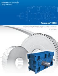
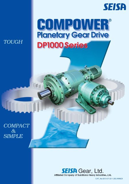
<strong>Planetary</strong> <strong>Gear</strong> <strong>Drive</strong><br />
DP1000 Series<br />
<strong>Gear</strong>, Ltd.<br />
Affiliated Company of Sumitomo Heavy Industries, Ltd.
A<br />
B<br />
C<br />
D<br />
E<br />
Features ......................................................................A-2<br />
Available Combination<br />
<strong>Drive</strong> Units and Reducer ...........................................A-4<br />
Basic Motor .........................................................A-6<br />
Reducer<br />
Standard Specifications.............................................B-2<br />
Construction Drawing...............................................B-3<br />
Nomenclature .......................................................B-4<br />
Selection ............................................................B-6<br />
Service Factor SF...................................................B-8<br />
Selection Tables .................................................. B-10<br />
Allowable Radial Load on Low Speed Shaft ..................... B-28<br />
Allowable Radial Load on High Speed Shaft .................... B-29<br />
Dimension Tables ................................................. B-30<br />
<strong>Drive</strong> Unit<br />
Standard Specifications.............................................C-2<br />
Construction Drawing...............................................C-3<br />
Nomenclature .......................................................C-4<br />
Selection ............................................................C-6<br />
Service Factor SF...................................................C-8<br />
Selection Tables .................................................. C-10<br />
Allowable Radial Load on Low Speed Shaft ..................... C-24<br />
Dimension Tables ................................................. C-26<br />
Applications<br />
Stacker/Reclaimer<br />
Bucket Wheel <strong>Drive</strong><br />
Simple Selection Table .............................................D-2<br />
Nomenclature .......................................................D-3<br />
Dimension Table ....................................................D-3<br />
Dimensions for Hollow Shaft .......................................D-4<br />
Selection Table......................................................D-5<br />
Slewing <strong>Drive</strong><br />
Simple Selection Table .............................................D-6<br />
Nomenclature .......................................................D-9<br />
Dimension Table ....................................................D-9<br />
Selection Table.................................................... D-10<br />
Technical Data<br />
Lubricant and Installation ...........................................E-2<br />
Painting Specifications and Rust Proof Standard..................E-3<br />
Moment of Inertia ...................................................E-4<br />
Specifications/Dimensions for Spline shaft ........................E-6<br />
Dimensions of Motor Adapter JEM / IEC ..........................E-7<br />
Recommended Couplings ..........................................E-8<br />
Warranty Policy ................................................... E-11<br />
Safety Precautions................................................ E-12<br />
Inquiry / Order Specification Sheet form ......................... E-13<br />
A―1
A-2
A<br />
Features<br />
Features ............................................................ A-2<br />
Available Combination<br />
Reducer and <strong>Drive</strong> Unit ................................ A-4<br />
Basic Motor .............................................. A-6
■ A Features<br />
● ● ● ● ● ● ● ● ● ● ● ● ● ● ● ● ● ●<br />
■Features<br />
“TOUGH, COMPACT & SIMPLE”<br />
1 Wide Variation of Lineup<br />
Applicable to various specifications with less number of parts by adopting modular design.<br />
Wide selection of <strong>Planetary</strong> <strong>Gear</strong> Reducer DP1000 Series for better choice of customer’s requests.<br />
1Availability of Output Torque from 0.46kNm to 736kNm and Power Range from 0.2kW to 1200kW.<br />
2Applicable to Reduction Ratio from 1/16 to 1/1400.<br />
3Applicable to foot mounting, flange mounting and shaft mounting(option).<br />
Reduction ratio<br />
5<br />
9<br />
16<br />
18<br />
20<br />
22.4<br />
25<br />
28<br />
31.5<br />
35.5<br />
40<br />
45<br />
50<br />
56<br />
63<br />
71<br />
80<br />
90<br />
100<br />
112<br />
125<br />
140<br />
160<br />
180<br />
200<br />
224<br />
250<br />
280<br />
315<br />
355<br />
400<br />
450<br />
500<br />
560<br />
630<br />
710<br />
800<br />
900<br />
1000<br />
1120<br />
1250<br />
1400<br />
Size of Reducer/torque(kNm)<br />
1010 1020 1030 1040 1050 1060 1070 1080 1090 1100 1110 1120 1130 1140 1150 1160 1170 1180 1190 1200 1210 1220<br />
0.46 0.69 1 1.6 3.2 5.5 8.6 13.6 15.9 22.6 29.4 39.2 53 72.6 95.2 128 157 186 275 402 549 736<br />
A-2
A Features ■<br />
● ● ● ● ● ● ● ● ● ● ● ● ● ● ● ● ● ●<br />
2 <strong>Drive</strong> Unit<br />
Prepared full lineup of direct motor mount type drive units.<br />
Simple layout of models can be made due to the unified combination of reducer and basic motor.<br />
Eliminate the necessity for foundation working for installation and alignment operation.<br />
3 High strength and rigidity of <strong>Planetary</strong> <strong>Gear</strong> system.<br />
1Equal distribution of <strong>Planetary</strong> <strong>Gear</strong> system.<br />
Optimum distribution of load to each gear is secured by <strong>Planetary</strong> <strong>Gear</strong> system and structure.<br />
Slimmer diameter can produce bigger transmission power of torque.<br />
2High pressure angle gear.<br />
27-degree pressure angle provides higher tooth strength, which is good for shock loads.<br />
27°Pressure Angle<br />
20°Pressure Angle<br />
A―3
■ A Features<br />
● ● ● ● ● ● ● ● ● ● ● ● ● ● ● ● ● ●<br />
■Available Combination<br />
Reducer<br />
Size<br />
Ratio 5 9 16 18 20 22.4 25 28 31.5 35.5 40 45 50 56 63 71 80 90 100 112 125<br />
1010 ● ● ● ● ● ● ● ● ● ●<br />
1020 ● ● ● ● ● ● ● ● ● ●<br />
1030 ● ● ● ● ● ● ● ● ● ●<br />
1040 ● ● ● ○ ○ ● ● ○ ● ● ● ● ●<br />
1050 ● ● ● ○ ○ ● ● ○ ● ● ○ ○ ● ○ ● ○ ○ ●<br />
1060 ● ● ● ○ ○ ● ○ ○ ● ○ ● ● ○ ○ ● ○ ● ○ ○ ●<br />
1070 ● ● ● ○ ○ ● ○ ○ ● ○ ● ○ ● ○ ○ ● ○ ● ○ ○ ●<br />
1080 ● ○ ○ ● ○ ○ ● ○ ● ○ ● ○ ○ ● ○ ● ○ ○ ●<br />
1090 ● ○ ○ ● ○ ○ ● ○ ○ ○ ● ○ ○ ● ○ ● ○ ○ ●<br />
1100 ○ ○ ● ● ● ● ● ● ● ● ● ○ ○ ● ○ ○<br />
1110 ○ ○ ● ● ● ● ● ● ● ● ● ○ ○ ● ○ ○<br />
1120 ○ ○ ● ● ● ● ● ● ● ● ● ○ ○ ● ○ ○<br />
1130 ○ ○ ● ● ● ● ● ● ● ● ● ○ ○ ● ○ ○<br />
1140 ○ ○ ● ● ● ● ● ● ● ● ○ ○ ● ● ● ●<br />
1150 ● ● ● ● ● ●<br />
1160 ● ● ● ● ● ●<br />
1170 ● ● ● ● ●<br />
1180 ● ● ● ● ●<br />
1190 ● ● ● ● ●<br />
1200 ● ● ● ●<br />
1210 ● ● ● ●<br />
1220 ● ● ● ● ●<br />
●:Standard Models ○:Manufactured Models (Option)<br />
Remark: This table is applicable only to shaft inline type in the catalogue.<br />
<strong>Drive</strong> Unit<br />
Ratio 5 9 16 18 20 22.4 25 28 31.5 35.5 40 45 50 56 63 71 80 90 100 112 125<br />
O/P speed 60Hz 360 200 113 100 90 80 72 64 57 51 45 40 36 32 29 25 23 20 18 16 14<br />
r/min 50Hz 300 167 94 83 75 67 60 54 48 42 38 33 30 27 24 21 19 17 15 13 12<br />
0.2×4 ● ● ●<br />
0.4×4 ● ● ●<br />
0.75×4 ● ● ● ● ● ●<br />
1.5×4 ● ● ● ● ● ● ● ● ●<br />
2.2×4 ● ● ● ● ● ● ● ● ● ●<br />
3.7×4 ● ● ● ● ● ● ● ● ● ●<br />
5.5×4 ● ● ● ● ● ● ● ● ● ●<br />
Motor 7.5×4 ● ● ● ● ● ● ● ● ● ●<br />
(kW × P) 11×4 ● ● ● ● ● ● ● ● ● ●<br />
15×4 ● ● ● ● ● ● ● ● ● ●<br />
18.5×4 ● ●<br />
22×4 ● ● ● ● ● ● ● ● ● ● ●<br />
30×4 ● ● ● ● ● ● ● ●<br />
37×4 ● ● ● ● ● ● ● ● ● ●<br />
45×4 ● ● ● ● ● ● ●<br />
55×4 ● ● ● ● ● ●<br />
Remark: This table is applicable only for shaft inline type in the catalogue.<br />
A-4
A Features ■<br />
● ● ● ● ● ● ● ● ● ● ● ● ● ● ● ● ● ●<br />
140 160 180 200 224 250 280 315 355 400 450 500 560 630 710 800 900 1000 1120 1250 1400 Ratio<br />
● ● ● ● ● ● ● ● 1010<br />
● ● ● ● ● ● ● ● 1020<br />
● ● ● ● ● ● ● ● 1030<br />
● ● ● ● ● ● ● ● 1040<br />
○ ○ ● ○ ● ● ● ● ● ● ● 1050<br />
○ ○ ● ○ ● ● ● ● ● ● ● 1060<br />
○ ○ ● ○ ● ● ● ● ● ● ● 1070<br />
○ ○ ● ○ ● ● ○ ● ○ ○ ● ○ ○ ● ○ ○ ● ○ ● 1080<br />
○ ○ ● ○ ● ● ○ ● ○ ○ ● ○ ○ ● ○ ○ ● ○ ● 1090<br />
● ○ ● ● ○ ● ○ ○ ● ○ ○ ● ○ ● ● ○ ● 1100<br />
● ○ ● ○ ● ○ ● ○ ○ ● ○ ○ ● ○ ● ● ○ ● 1110<br />
● ○ ● ○ ● ○ ● ○ ○ ● ○ ○ ● ○ ● ● ○ ● 1120<br />
● ○ ○ ○ ● ○ ● ○ ○ ● ○ ○ ● ○ ○ ● ○ ○ 1130<br />
● ● ● ● ● ○ ○ ● ○ ○ ● ○ ○ 1140<br />
● ● ● ● ● ● ● ● ● ● ● ● ● ● 1150<br />
● ● ● ● ● ● ● ● ● ● ● ● ● ● 1160<br />
● ● ● ● ● ● ● ● ● ● ● ● ● ● 1170<br />
● ● ● ● ● ● ● ● ● ● ● ● ● ● ● 1180<br />
● ● ● ● ● ● ● ● ● ● ● ● ● ● ● 1190<br />
● ● ● ● ● ● ● ● ● ● ● ● ● ● 1200<br />
● ● ● ● ● ● ● ● ● ● ● ● ● ● ● 1210<br />
● ● ● ● ● ● ● ● ● ● ● ● ● ● ● 1220<br />
Size<br />
140 160 180 200 224 250 280 315 355 400 450 500 560 630 710 800 900 1000 1120 1250 1400 Ratio<br />
13 11 10 9.0 8.0 7.2 6.4 5.7 5.1 4.5 4.0 3.6 3.2 2.9 2.5 2.3 2.0 1.8 1.6 1.4 1.3 60Hz O/P speed<br />
11 9.4 8.3 7.5 6.7 6.0 5.4 4.8 4.2 3.8 3.3 3.0 2.7 2.4 2.1 1.9 1.7 1.5 1.3 1.2 1.1 50Hz r/min<br />
● ● ● ● ● ● ● ● 0.2×4<br />
● ● ● ● ● ● ● ● 0.4×4<br />
● ● ● ● ● ● ● ● 0.75×4<br />
● ● ● ● ● ● ● ● ● 1.5×4<br />
● ● ● ● ● ● ● ● ● 2.2×4<br />
● ● ● ● ● ● ● ● ● ● 3.7×4<br />
● ● ● ● ● ● ● ● 5.5×4<br />
● ● ● ● ● ● ● ● 7.5×4 Motor<br />
● ● ● ● ● ● ● 11×4 (kW × P)<br />
● ● ● ● ● 15×4<br />
● ● ● ● ● ● 18.5×4<br />
● ● ● ● ● ● ● 22×4<br />
● 30×4<br />
37×4<br />
45×4<br />
55×4<br />
A―5
■ A Features<br />
● ● ● ● ● ● ● ● ● ● ● ● ● ● ● ● ● ●<br />
Basic Motor<br />
3-Phase Induction Motors<br />
4 Pole ●Standard Insulation ○Manufactured Models<br />
3-Phase Induction Motors with Built-in Brakes<br />
4 Pole ●Standard Insulation ○Manufactured Models<br />
Capacity<br />
Corrosionproof<br />
(Constant Torque)<br />
Inverter Motors<br />
Insulation Class<br />
Indoor Type Outdoor Type<br />
kW<br />
Class2 E B F H Indoor Type Outdoor Type<br />
0.2 ○ ○ ○ ● ○ ○ ○ ○ ○<br />
0.25 ○ ○ ○ ● ○ ○ ○<br />
0.4 ○ ○ ○ ● ○ ○ ○ ○ ○<br />
0.55 ○ ○ ○ ● ○ ○<br />
0.75 ○ ○ ○ ● ○ ○ ○ ○<br />
1.1 ○ ○ ○ ● ○ ○<br />
1.5 ○ ○ ○ ● ○ ○ ○ ○<br />
2.2 ○ ○ ○ ● ○ ○ ○ ○<br />
3.0 ○ ○ ○ ● ○ ○<br />
3.7 ○ ○ ○ ● ○ ○ ○ ○<br />
5.5 ○ ○ ○ ● ○ ○ ○ ○<br />
7.5 ○ ○ ○ ● ○ ○ ○ ○<br />
11 ○ ○ ○ ● ○ ○ ○ ○<br />
15 ○ ○ ○ ● ○ ○ ○ ○<br />
18.5 ○ ○ ○ ● ○ ○ ○ ○<br />
22 ○ ○ ○ ● ○ ○ ○ ○<br />
30 ○ ○ ○ ● ○ ○ ○<br />
37 ○ ○ ○ ● ○ ○ ○<br />
45 ○ ○ ○ ● ○ ○ ○<br />
55 ○ ○ ○ ● ○ ○ ○<br />
Remarks: Continuous Rating: 55kW and under. Applicable Voltage: 200V 50/60Hz (400V 50/60Hz, 440V 60Hz)<br />
Provided that the base frequency for driving an inverter is 60Hz.<br />
Capacity<br />
Corrosionproof<br />
(Constant Torque)<br />
Inverter Motors<br />
Insulation Class<br />
Indoor Type Outdoor Type<br />
kW<br />
Class2 E B F H Indoor Type Outdoor Type<br />
0.2 ○ ○ ○ ● ○ ○ ○ ○ ○<br />
0.25 ○ ○ ○ ● ○ ○ ○<br />
0.4 ○ ○ ○ ● ○ ○ ○ ○ ○<br />
0.55 ○ ○ ○ ● ○ ○<br />
0.75 ○ ○ ○ ● ○ ○ ○ ○<br />
1.1 ○ ○ ○ ● ○ ○<br />
1.5 ○ ○ ○ ● ○ ○ ○ ○<br />
2.2 ○ ○ ○ ● ○ ○ ○ ○<br />
3.0 ○ ○ ○ ● ○ ○<br />
3.7 ○ ○ ○ ● ○ ○ ○ ○<br />
5.5 ○ ○ ○ ● ○ ○ ○ ○<br />
7.5 ○ ○ ○ ● ○ ○ ○ ○<br />
11 ○ ○ ○ ● ○ ○ ○ ○<br />
15 ○ ○ ○ ● ○ ○ ○ ○<br />
18.5 ○ ○ ○ ● ○ ○ ○ ○<br />
22 ○ ○ ○ ● ○ ○ ○ ○<br />
30 ○ ○ ○ ● ○<br />
37 ●<br />
Remarks: Continuous Rating: 55kW and under. Applicable Voltage: 200V 50/60Hz (400V 50/60Hz, 440V 60Hz)<br />
Provided that the base frequency for driving an inverter is 60Hz.<br />
Brake Insulation: B type<br />
Note: 1. Motors with output kW specifications other than as listed in Tables 1-4 are also manufactured. Please send us your inquiry.<br />
Examples: Special voltage, dust-proof, humidity-proof, tropical treatment, high temperature, ship use, dual shaft-round &<br />
square, CSA standard, NEMA standard, etc.<br />
2. For inverter drive use, refer to ambient temperature, input r/min, mounting method, load characteristics.<br />
A-6
A Features ■<br />
● ● ● ● ● ● ● ● ● ● ● ● ● ● ● ● ● ●<br />
Safety Increased Explosion-proof (eG3) 3-Phase Induction Motor<br />
4 pole ●Standard Insulation ○Manufactured Models<br />
Capacity Corrosion-proo Insulation Class<br />
Indoor Type<br />
Outdoor Type<br />
kW<br />
Class 2 B F<br />
0.2 ○ ○ ○ ● ○<br />
0.4 ○ ○ ○ ● ○<br />
0.75 ○ ○ ○ ● ○<br />
1.5 ○ ○ ○ ● ○<br />
2.2 ○ ○ ○ ● ○<br />
3.7 ○ ○ ○ ● ○<br />
5.5 ○ ○ ○ ● ○<br />
7.5 ○ ○ ○ ● ○<br />
11 ○ ○ ○ ● ○<br />
15 ○ ○ ○ ●<br />
18.5 ○ ○ ○ ●<br />
22 ○ ○ ○ ●<br />
30 ○ ○ ○ ● ○<br />
37 ○ ○ ○ ●<br />
45 ○ ○ ○ ●<br />
55 ○ ○ ○ ●<br />
Remarks: Continuous Rating<br />
Applicable Voltage: 200V, 220V, 350V, 380V, 400V, 440V, 50/60Hz<br />
Pressure-tight Explosion-proof (d2G4) 3-Phase Motor<br />
4 pole ●Standard Insulation ○Manufactured Models<br />
Capacity Corrosion-proof Insulation Class<br />
Indoor Type<br />
Outdoor Type<br />
kW<br />
Class 2 B F<br />
0.2 ○ ○ ○ ○ ○<br />
0.4 ○ ○ ○ ○ ○<br />
0.75 ○ ○ ○ ● ○<br />
1.5 ○ ○ ○ ● ○<br />
2.2 ○ ○ ○ ● ○<br />
3.7 ○ ○ ○ ● ○<br />
5.5 ○ ○ ○ ● ○<br />
7.5 ○ ○ ○ ● ○<br />
11 ○ ○ ○ ● ○<br />
15 ○ ○ ○ ● ○<br />
22 ○ ○ ○ ● ○<br />
30 ○ ○ ○ ● ○<br />
37 ○ ○ ○ ○<br />
Remarks: Continuous Rating<br />
Applicable Voltage: 200V, 220V, 350V, 380V, 400V, 440V, 50/60Hz<br />
(Inverter Motors): 200V 60Hz, 220V 60Hz, 400V 60Hz<br />
Applicable Inverter: Applicable only to Sumitomo Inverters. (Refer to Inverter catalogue.)<br />
Safety Precautions<br />
For inverter drive use of Explosion-proof type, the combination of motor and inverter is defined by<br />
authorization. Always use the defined inverter specified.<br />
As inverter itself is not explosion-proof construction, please always set the inverter at the place<br />
where any explosive gas is not available.<br />
A―7
■ A Features<br />
● ● ● ● ● ● ● ● ● ● ● ● ● ● ● ● ● ●<br />
A-8
B<br />
Reducer<br />
Reducer<br />
Standard Specifications ........................................B-2<br />
Construction Drawing...........................................B-3<br />
Nomenclature ....................................................B-4<br />
Selection..........................................................B-6<br />
Service Factor SF ...............................................B-8<br />
Selection Tables ............................................... B-10<br />
Allowable Radial Load on Low Speed Shaft............... B-28<br />
Allowable Radial Load on High Speed Shaft .............. B-29<br />
Dimension Tables ............................................. B-30
■ B Reducer<br />
● ● ● ● ● ● ● ● ● ● ● ● ● ● ● ● ● ●<br />
■Reducer Standard Specifications<br />
Reducer<br />
Ambient Conditions<br />
Item<br />
Lubrication<br />
Method<br />
Standard Specification<br />
Oil bath lubrication<br />
(Some of the upper bearing are lubricated with grease)<br />
Lubricant Refer to the page E-2<br />
Reduction<br />
Involute <strong>Planetary</strong> <strong>Gear</strong><br />
Method<br />
Shaft<br />
Rotation direction of high speed shaft is the same as output shaft<br />
Direction<br />
Installation<br />
Indoor (Minimal dust and humidity)<br />
Location<br />
Ambient<br />
Temperature -10℃~40℃<br />
Ambient<br />
Humidity<br />
Under 85%<br />
Elevation Under 1,000 meters<br />
Atmosphere Well-ventilated location, free of corrosive gas, explosive gas, vapors and dust.<br />
Horizontal installation<br />
Installation<br />
Refer to the page E-2.<br />
Method of<br />
Coupling with Coupling, gears, chain sprocket or belt.<br />
driven Machine<br />
Surface preparation: Shot blasting after washing before machining.<br />
Inside painting: UNI GROUND PTC primer is sprayed once.<br />
Painting Outside painting: For prime coating, UNI GROUND PTC primer is sprayed once.<br />
For final coating, SUPIKA#3000 is sprayed once.<br />
Painting color: MUNSELL 2.5G 6/3. Refer to the page E-3.<br />
Note1: A heating or cooling system is necessary in case the ambient temperature is lower than -10℃ or higher than +40℃.<br />
B-2
B Reducer ■<br />
● ● ● ● ● ● ● ● ● ● ● ● ● ● ● ● ● ●<br />
■Construction Drawing<br />
DHF (flange type)<br />
No. Part Name No. Part Name<br />
1 Low Speed Shaft 6 Internal <strong>Gear</strong><br />
2 Seal Cover 7 Sun <strong>Gear</strong><br />
3 Case 8 Inter Mediate Cover<br />
4 Bearing 9 High Speed Shaft Cover<br />
5 <strong>Planetary</strong> <strong>Gear</strong> 10 High Speed Shaft<br />
B―3
■ B Reducer<br />
● ● ● ● ● ● ● ● ● ● ● ● ● ● ● ● ● ●<br />
■Nomenclature<br />
D HG 1090<br />
Series Shaft Direction and Mounting Style Connection for Motor<br />
D<br />
DP 1000<br />
Series<br />
<strong>Planetary</strong> <strong>Gear</strong><br />
<strong>Drive</strong><br />
HG Horizontal<br />
HF Horizontal Flange<br />
VF Vertical Flange<br />
(Blank) Solid Shaft<br />
J Motor Adaptor<br />
JM Motor Adaptor + Motor<br />
Size<br />
Torque kNm<br />
1010 0.46<br />
1020 0.69<br />
1030 1.0<br />
1040 1.6<br />
1050 3.2<br />
1060 5.5<br />
1070 8.6<br />
1080 13.6<br />
1090 15.9<br />
1100 22.6<br />
1110 29.4<br />
1120 39.2<br />
1130 53.0<br />
1140 72.6<br />
1150 95.2<br />
1160 128<br />
1170 157<br />
1180 186<br />
1190 275<br />
1200 402<br />
1210 549<br />
1220 736<br />
Remarks:<br />
Above figures of Torque show<br />
the transmission power of low<br />
speed shaft.<br />
HY Shaft mounting<br />
(Option)<br />
B-4
B Reducer ■<br />
● ● ● ● ● ● ● ● ● ● ● ● ● ● ● ● ● ●<br />
90<br />
Direction of High Speed Shaft Low Speed Shaft Option Nominal Ratio<br />
(Blank)Inline<br />
G※ Right angle<br />
(Option)<br />
※Following Direction code will<br />
be added.<br />
Direction code<br />
(View from A)<br />
L<br />
left<br />
U<br />
D<br />
View from A<br />
up<br />
down<br />
※”GR” will apply to VF type in<br />
spite of Direction code.<br />
R<br />
right<br />
(Blank)Solid Shaft<br />
Key type<br />
P Spline<br />
(Option)<br />
T Hollow Shaft Shrink Disk<br />
type (Option)<br />
(Blank)Standard<br />
Specification<br />
F Cooling Fan<br />
(Option)<br />
R Radial Case<br />
(Option)<br />
5<br />
9<br />
16<br />
18<br />
20<br />
22.4<br />
25<br />
28<br />
31.5<br />
35.5<br />
40<br />
45<br />
50<br />
56<br />
63<br />
71<br />
80<br />
90<br />
100<br />
112<br />
125<br />
140<br />
160<br />
180<br />
200<br />
224<br />
250<br />
280<br />
315<br />
355<br />
400<br />
450<br />
500<br />
560<br />
630<br />
710<br />
800<br />
900<br />
1000<br />
1120<br />
1250<br />
1400<br />
B―5
■ B Reducer<br />
● ● ● ● ● ● ● ● ● ● ● ● ● ● ● ● ● ●<br />
■Reducer Selection<br />
B-6
B Reducer ■<br />
● ● ● ● ● ● ● ● ● ● ● ● ● ● ● ● ● ●<br />
■Reducer Selection Example<br />
Conditions and final selections ○:Conditions ■:Selected item Reference page No.<br />
○ Ambient Condition :indoor, Ambient temperature 25℃ B-2:Standard Specification<br />
■ Check ambient condition<br />
→OK<br />
○ Motor power<br />
:22kW(Code:30)<br />
○ High speed shaft speed<br />
:1500r/min<br />
○ Shaft and mounting positions :Right Angle Shaft, Horizontal Mounting<br />
Load condition<br />
○ Type of load, operating hours, usage :Uniform load: 14 hours/day, conveyor<br />
■ Determine Service Factor →SF=1.25 B-8:Service Factor<br />
■ Calculate equivalent transmission power →P E =22×1.25=27.5kW<br />
○ Low speed shaft speed<br />
:20r/min<br />
■ Reduction ratio<br />
→1500/20=75<br />
Select nominal reduction ratio →75→71 B-4~B-5:Nomenclature<br />
■ Determine size<br />
■ Determine reducer size, type,<br />
reduction ratio<br />
→ Size 1090 Nominal reduction ratio<br />
71<br />
Mechanical power rating P N =34.2kW<br />
P E ≦ P N → OK<br />
B-16:Selection Tables<br />
■ Check dimension<br />
B-32 *1 :Dimension Tables<br />
■ Check nomenclature →DHG-1090-71 Code in Dimension Tables<br />
○ Ambient Temperature :20℃<br />
■ Temperature correction factor K1 →K1=1.0 B-9:Selection Tables<br />
■ Temperature correction factor K2 →K2=1.0 B-9:Selection Tables<br />
■ Thermal power rating P T →P T =32.0kW B-14:Selection Tables<br />
→P T ×K1×K2=32.0>22=P M →OK<br />
Check overhang load<br />
○ Overhang member<br />
:Sprocket (Single row)<br />
■ Overhang factor K3 →K3=1.0 B-28:Allowable Radial Load<br />
○ Radial load position<br />
:Center of shaft<br />
○ Radial load Fr<br />
:60kN<br />
■ Equivalent radial load F rE →F rE =60×1.25×1.0=75kN<br />
■ Allowable radial load →100kN B-28:Allowable Radial Load<br />
75<br />
100<br />
= 0.75 < 1 →OK<br />
○ Completion of selection<br />
■ Model selected<br />
→DHG-1090-71<br />
*1 page number of the relevant Dimension Table<br />
is indicated in the Selection Table.<br />
B―7
■ B Reducer<br />
● ● ● ● ● ● ● ● ● ● ● ● ● ● ● ● ● ●<br />
■Service Factorer SF<br />
Service Factor Table for <strong>Drive</strong>n Machines<br />
CRANES<br />
Classification<br />
of crane<br />
<strong>Drive</strong>n Machine<br />
Hoisting<br />
Ttaverse<br />
Motion<br />
Travel<br />
Motion<br />
Slewing<br />
Motion<br />
Operating Hours(hours/day)<br />
3 hrs 10 hrs 24 hrs<br />
Boom<br />
Hoisting<br />
GroupⅠ 1.00 1.50 1.25 1.00<br />
GroupⅡ 1.25 1.50 1.00<br />
GroupⅢ 1.50 1.75 1.25<br />
GroupⅣ 1.75 2.00 1.50<br />
The crane classification is<br />
based on JIS.<br />
「Calculation standard for<br />
the structure of crane」<br />
CONVEYORS(General purpose)<br />
Uniformly load or fed 1.00 1.00 1.25<br />
Heavy load<br />
Not uniformly fed 1.00 1.25 1.50<br />
Reciprocating or shaker 1.50 1.75 2.00<br />
ELEVATORS<br />
Elevators 1.50 1.50 1.50<br />
Escalators 1.25 1.25 1.25<br />
METAL MILLS<br />
Draw bench carriage・main drive 1.50 1.50 1.50<br />
Runout table<br />
Non reversing<br />
Group drives 1.50 1.50 1.50<br />
Individual drives 2.00 2.00 2.00<br />
Reversing 2.00 2.00 2.00<br />
Slab pushers 1.50 1.50 1.50<br />
Shears 2.00 2.00 2.00<br />
Wire drawing 1.25 1.25 1.25<br />
Wire winding machine 1.25 1.50 1.50<br />
MATAL STRIP PROCESSING MACHINERY<br />
Bridles 1.50 1.50 1.50<br />
Coilers & uncoilers 1.00 1.25 1.50<br />
Edge trimmers 1.00 1.25 1.50<br />
Flatteners 1.25 1.25 1.50<br />
Loopers 1.50 1.50 2.00<br />
Pinch rolls 1.25 1.25 1.50<br />
Scrap choppers 2.00 2.00 2.00<br />
Shears 2.00 2.00 2.00<br />
Slitters 1.00 1.25 1.50<br />
MILL、ROTARY TYPE<br />
Ball、Rod 2.00 2.00 2.00<br />
Cement Kilns 2.00 2.00 2.00<br />
Kilns (Except cement kilns) 1.50 1.50 1.50<br />
Dryers、Coolers 1.50 1.50 1.50<br />
SEWAGE DISPOSAL EQUIPMENT<br />
Aerators 2.00 2.00 2.00<br />
Bar screens 1.25 1.25 1.25<br />
Chemical feeders 1.25 1.25 1.25<br />
Dewatering screens 1.50 1.50 1.50<br />
Scum breakers 1.50 1.50 1.50<br />
mixers 1.50 1.50 1.50<br />
Sludge collectors 1.25 1.25 1.25<br />
Thickeners 1.50 1.50 1.50<br />
Vacuum filters 1.50 1.50 1.50<br />
EXTRUDERS<br />
Plastics 1.25 1.25 1.25<br />
Rubber 1.50 1.50 1.50<br />
FEEDERS<br />
Apron 1.00 1.25 1.50<br />
Belt 1.00 1.25 1.50<br />
Disk 1.00 1.00 1.25<br />
Reciprocating 1.50 1.75 2.00<br />
Screw 1.00 1.25 1.50<br />
<strong>Drive</strong>n Machine<br />
Operating Hours(hours/day)<br />
3 hrs 10 hrs 24 hrs<br />
RUBBER INDUSTRY<br />
Mixers 1.75 1.75 2.00<br />
Mixing mill -2smooth rolls 1.50 1.50 1.75<br />
Batch drop mill -2smooth rolls 1.50 1.50 1.50<br />
Cracker warmer<br />
-2roll:1 corrugated roll 1.75 1.75 1.75<br />
-2roll:1 corrugated roll 2.00 2.00 2.00<br />
Holding,feed & blend mill<br />
-2rolls 1.25 1.25 1.25<br />
Refiner -2 rolls 1.50 1.50 1.50<br />
Calenders 1.50 1.50 1.50<br />
PAPER MILL<br />
Alltypes incl.Paper making machine 2.00 2.00 2.00<br />
AGITATORS<br />
Liquids 1.00 1.00 1.25<br />
Liquids and solids 1.00 1.25 1.50<br />
Liquids Variable density 1.00 1.25 1.50<br />
MIXERS<br />
Concrete 1.25 1.25 1.50<br />
CRUSHER<br />
Stone 2.50 2.50 2.50<br />
BLOWERS<br />
Centrifugal 1.00 1.00 1.25<br />
Lobe 1.00 1.25 1.50<br />
Vane 1.00 1.25 1.50<br />
COMPRESSORS<br />
Centrifugal 1.00 1.00 1.25<br />
Lobe 1.00 1.25 1.50<br />
Reciprocating、multi cylinder 1.50 1.50 1.75<br />
Reciprocating、single cylinder 1.75 1.75 2.00<br />
FANS<br />
Centrifugal 1.00 1.00 1.25<br />
Cooling towers ※ ※ ※<br />
Forced draft 1.25 1.25 1.25<br />
Suction draft 1.50 1.50 1.50<br />
Idustrial、mine 1.50 1.50 1.50<br />
PUMPS<br />
Centrifugal 1.00 1.00 1.25<br />
Screw pump 1.25 1.25 1.50<br />
<strong>Gear</strong> pump 1.25 1.25 1.50<br />
DREDGES<br />
Cable reels 1.25 1.25 1.50<br />
Conveyors 1.25 1.25 1.50<br />
Cutter head drive 2.00 2.00 2.00<br />
Pumps 2.00 2.00 2.00<br />
Screen drives 1.75 1.75 2.00<br />
Stackers 1.25 1.25 1.50<br />
Winches 1.25 1.25 1.50<br />
GENERATORS 1.00 1.00 1.25<br />
HAMMER MILLS 1.75 1.75 2.00<br />
SUGAR INDUSTRY<br />
Beet slicer 2.00 2.00 2.00<br />
Cane knives 1.50 1.50 1.50<br />
Crushers 1.50 1.50 1.50<br />
Mills 1.75 1.75 1.75<br />
Notes<br />
(1) Values in the above table are based on AGMA standard and SEISA’s experience.<br />
(2) Values in the above table apply for electric motors as prime movers if prime<br />
mover is a multi cylinder combustion engine,0.25 has to be added to the SF.<br />
(3) Consult us for special duty or when special safety specifications are needed.<br />
(4) ※:Consult us.<br />
B-8
B Reducer ■<br />
● ● ● ● ● ● ● ● ● ● ● ● ● ● ● ● ● ●<br />
Refer to the following for driven machines not shown on the left page.<br />
Prime Mover Operating Hours Uniform Load<br />
U<br />
3 hours/day<br />
1.00<br />
Electric Motor 10 hours/day<br />
1.00<br />
24 hours/day<br />
1.25<br />
Internal Combustion<br />
Engine<br />
(multi cylinder)<br />
Note:<br />
3 hours/day<br />
10 hours/day<br />
24 hours/day<br />
1.00<br />
1.25<br />
1.50<br />
Type of Load<br />
Moderate Shock Load<br />
M<br />
1.00<br />
1.25<br />
1.50<br />
1.25<br />
1.50<br />
1.75<br />
Heavy Shock Load<br />
H<br />
1.50<br />
1.75<br />
2.00<br />
1.75<br />
2.00<br />
2.25<br />
Consult us when the operating hours are less then 3 hours/day or when an internal combustion engine (single<br />
cylinder) is used.<br />
Temperature correction factor K1<br />
K1<br />
Load ratio per hour<br />
Ambient temperature(℃)<br />
Under 10 20 30 40 50<br />
100% 1.15 1.00 0.85 0.70 0.55<br />
80% 1.35 1.20 1.00 0.80 0.65<br />
60% 1.55 1.40 1.15 0.95 0.75<br />
40% 1.75 1.60 1.35 1.10 0.90<br />
20% 1.95 1.80 1.50 1.20 1.00<br />
Note: Use 100% in case the operating hours will be more than two hours.<br />
Temperature correction factor K2<br />
Location Wind K2<br />
Indoor/closed ≧0.5m/s 0.7<br />
Indoor/open<br />
(Factory in general)<br />
Outdoor/without direct<br />
sunlight<br />
≧1.4m/s 1.0<br />
≧3.7m/s 1.4<br />
Overhang factor K3<br />
Overhang Member<br />
K3<br />
Sprocket(single row) 1<br />
Sprocket(double row) 1.25<br />
<strong>Gear</strong> 1.25<br />
V-belt 1.5<br />
Flat belt 2.5<br />
B―9
■ B Reducer<br />
● ● ● ● ● ● ● ● ● ● ● ● ● ● ● ● ● ●<br />
■Selection Table Reducer Reduction ratio 5・9<br />
Mechanical Power Rating P N<br />
Nominal<br />
Reduction<br />
H. Speed Shaft<br />
Speed n 1<br />
L. Speed Shaft<br />
Speedn 2<br />
Size of Reducer<br />
Ratio r/min r/min 1010 1020 1030 1040 1050 1060 1070 1080 1090<br />
Exact Reduction Ratio 5.053 5.053 5.053 5.053 5.053 5.053 5.053<br />
1800 360 4.39 7.65 11.7 11.7 23.5 43.0 86.9<br />
1500 300 3.67 6.33 9.80 10.1 19.6 35.8 72.4<br />
5 1200 240 2.86 5.10 7.86 8.06 15.7 28.7 58.0<br />
1000 200 2.45 4.18 6.53 6.73 13.1 23.9 48.3<br />
900 180 2.14 3.78 5.92 6.12 11.7 21.5 43.5<br />
750 150 1.84 3.16 4.90 5.10 9.80 18.0 36.2<br />
Exact Reduction Ratio 8.700 8.700 8.700 8.700 8.700 8.700 8.700<br />
1800 200 2.65 3.98 7.86 9.29 18.0 36.8 48.2<br />
1500 167 2.24 3.88 6.53 7.76 15.3 30.6 45.9<br />
9 1200 133 1.84 3.06 5.20 6.22 12.2 24.5 36.7<br />
1000 111 1.53 2.55 4.39 5.10 10.2 20.4 30.6<br />
900 100 1.33 2.35 3.88 4.59 9.18 18.4 27.6<br />
750 83 1.12 1.94 3.27 3.88 7.65 15.3 23.0<br />
Dimension Tables<br />
Horizontal B-30 B-30 B-30 B-30 B-30 B-30 B-30<br />
Flange, Horizontal B-36 B-36 B-36 B-36 B-36 B-36 B-36<br />
Thermal Power Rating P T 12.1 12.1 17.6 23.4 34.7 49.6 67.2<br />
Notes:<br />
1. The high speed shaft speed shall be under 1800 r/min. Consult us when it will be over 1800r/min.<br />
2. When the high speed shaft speed is not shown in the table, find it by the interpolation method.<br />
3. When the high speed shaft speed (n 1 ) id lower than 750 r/min, find the mechanical power rating (P N ) according to the following formula.<br />
P N =P750× N<br />
750<br />
4. Shown in the table are the ratings for the high speed shaft of reducer.<br />
5. The thermal power ratings (P T ) are applicable to continuous operation at ambient temperatures of 20℃ or less.<br />
B-10
B Reducer ■<br />
● ● ● ● ● ● ● ● ● ● ● ● ● ● ● ● ● ●<br />
Unit: kW<br />
Size of Reducer<br />
1100 1110 1120 1130 1140 1150 1160 1170 1180 1190 1200 1210 1220<br />
B―11
■ B Reducer<br />
● ● ● ● ● ● ● ● ● ● ● ● ● ● ● ● ● ●<br />
■Selection Table Reducer Reduction ratio 16~28<br />
Mechanical Power Rating P N<br />
Nominal<br />
Reduction<br />
H. Speed Shaft<br />
Speedn 1<br />
L. Speed Shaft<br />
Speedn 2<br />
Size of Reducer<br />
Ratio r/min r/min 1010 1020 1030 1040 1050 1060 1070 1080 1090<br />
Exact Reduction Ratio 16.17 16.17 16.17 16.17 16.17 16.17 16.17 16.17 16.17<br />
1800 113 3.13 4.75 7.50 9.68 22.5 38.0 65.5 104 130<br />
1500 94 2.96 4.49 7.10 9.17 21.3 36.0 62.0 98.0 120<br />
16 1200 75 2.77 4.20 6.64 8.57 18.0 31.8 50.0 75.5 94.3<br />
1000 63 2.62 3.82 6.10 7.19 15.0 26.5 41.7 62.9 78.6<br />
900 56 2.42 3.44 5.49 6.47 13.5 23.9 37.5 56.6 70.7<br />
750 47 2.02 2.87 4.57 5.40 11.3 19.9 31.3 47.2 59.0<br />
Exact Reduction Ratio ※ 18.29 ※ 18.29 ※ 18.29 ※ 18.29 ※ 18.29 ※ 18.29<br />
1800 100 9.14 21.6 35.2 61.7 96.5 126<br />
1500 83 8.66 20.4 33.3 58.4 91.4 111<br />
18 1200 67 7.84 18.0 31.1 50.0 74.5 88.8<br />
1000 56 6.53 15.0 26.5 41.7 62.1 74.0<br />
900 50 5.88 13.5 23.9 37.5 55.9 66.6<br />
750 42 4.90 11.3 19.9 31.3 46.5 55.5<br />
Exact Reduction Ratio ※ 19.68 ※ 19.68 ※ 19.68 ※ 19.68 ※ 19.68 ※ 19.68<br />
1800 90 8.69 20.4 33.4 58.6 91.7 109<br />
1500 75 8.02 19.3 31.6 55.5 86.8 90.9<br />
20 1200 60 6.42 15.9 29.6 48.1 71.0 72.7<br />
1000 50 5.35 13.2 25.5 40.1 59.2 60.6<br />
900 45 4.81 11.9 22.9 36.1 53.3 54.5<br />
750 38 4.01 9.93 19.1 30.0 44.4 45.4<br />
Exact Reduction Ratio 21.40 21.40 21.40 21.40 21.40 21.40 21.40 21.40 21.40<br />
1800 80 2.57 4.03 6.17 8.68 18.5 31.2 55.5 86.9 110<br />
1500 67 2.43 3.88 5.84 8.22 17.5 31.3 52.6 75.3 90.6<br />
22.4 1200 54 2.28 3.11 5.46 6.22 16.4 27.7 44.2 60.2 60.2<br />
1000 45 2.06 2.59 4.66 5.19 13.7 23.4 36.8 50.2 50.2<br />
900 40 1.85 2.33 4.20 4.67 12.3 21.1 33.2 45.2 45.2<br />
750 33 1.54 1.94 3.50 3.89 10.3 17.6 27.6 37.6 37.6<br />
Exact Reduction Ratio ※<br />
24.90 ※ 24.90 ※ 24.90 ※ 23.58<br />
1800 72 28.3 49.7 77.8 90.3<br />
1500 60 26.8 47.0 70.1 75.3<br />
25 1200 48 22.4 38.0 56.1 60.2<br />
1000 40 18.7 31.7 46.8 50.2<br />
900 36 16.8 28.5 42.1 45.2<br />
750 30 14.0 23.7 35.1 37.6<br />
Exact Reduction Ratio ※<br />
27.28 ※ 27.28 ※ 27.28 ※ 26.43<br />
1800 64 26.6 46.6 73.0 90.3<br />
1500 54 25.2 43.9 64.8 75.3<br />
28 1200 43 22.3 35.1 51.8 60.2<br />
1000 36 18.6 29.3 43.2 50.2<br />
900 32 16.8 26.3 38.9 45.2<br />
750 27 14.0 21.9 32.4 37.6<br />
Dimension Tables<br />
Horizontal B-31 B-31 B-31 B-31 B-31 B-31 B-31 B-31 B-31<br />
Flange, Horizontal B-37 B-37 B-37 B-37 B-37 B-37 B-37 B-37 B-37<br />
Thermal Power Rating P T 6.0 6.0 8.8 11.7 17.3 24.8 33.6 40.9 48.0<br />
Notes:<br />
1. The high speed shaft speed shall be under 1800 r/min. Consult us when it will be over 1800r/min.<br />
2. When the high speed shaft speed is not shown in the table, find it by the interpolation method.<br />
3. When the high speed shaft speed (n 1 ) id lower than 750 r/min, find the mechanical power rating (P N ) according to the following formula.<br />
4. Shown in the table are the ratings for the high speed shaft of reducer.<br />
5. The thermal power ratings (P T ) are applicable to continuous operation at ambient temperatures of 20℃ or less.<br />
B-12
B Reducer ■<br />
● ● ● ● ● ● ● ● ● ● ● ● ● ● ● ● ● ●<br />
Unit: kW<br />
Size of Reducer<br />
1100 1110 1120 1130 1140 1150 1160 1170 1180 1190 1200 1210 1220<br />
※ 16.17 ※ 16.17 ※ 16.17 ※ 16.17 ※ 16.17<br />
174 245 310 421 459<br />
146 215 273 370 404<br />
117 184 234 317 345<br />
97.3 161 206 279 304<br />
87.5 145 191 259 282<br />
73 121 161 224 249<br />
※ 18.29 ※ 18.29 ※ 18.29 ※ 18.29 ※ 18.29<br />
155 225 285 386 421<br />
129 198 251 340 371<br />
103 169 214 291 317<br />
86.0 142 189 256 279<br />
77.4 128 171 238 259<br />
64.5 107 143 199 228<br />
19.68 19.68 20.07 20.07 20.07<br />
144 213 267 339 394<br />
120 188 235 299 347<br />
95.9 158 201 255 297<br />
79.9 132 173 225 261<br />
71.9 119 156 209 243<br />
59.9 99.9 130 181 214<br />
22.98 22.98 22.98 22.98 22.98<br />
136 191 243 303 359<br />
120 168 214 267 316<br />
102 136 181 228 270<br />
87.6 114 152 201 238<br />
79.0 103 137 187 221<br />
66.0 85.7 114 159 194<br />
24.90 24.90 24.90 24.90 24.90<br />
129 181 229 284 339<br />
113 157 202 250 299<br />
96.8 126 168 214 255<br />
81.0 105 140 188 225<br />
73.0 94.8 126 175 209<br />
61.0 79.2 106 147 184<br />
27.28 27.28 27.28 27.28 27.28<br />
121 170 215 263 318<br />
106 143 189 232 280<br />
88.6 115 153 198 240<br />
74.0 96.1 128 174 211<br />
66.7 86.6 115 160 196<br />
55.8 72.4 96.5 134 172<br />
B-31 B-31 B-31 B-31 B-31<br />
B-37 B-37 B-37 B-37 B-37<br />
48.5 57.6 70.5 84.1 101<br />
※Those reduction ratios will be available as option. We, however, recommend standard reduction ratio considering extra cost and<br />
delivery date.<br />
B―13
■ B Reducer<br />
● ● ● ● ● ● ● ● ● ● ● ● ● ● ● ● ● ●<br />
■Selection Table Reducer Reduction ratio 31.5~45<br />
Mechanical Power Rating P N<br />
Nominal<br />
Reduction<br />
H. Speed Shaft<br />
Speedn 1<br />
L. Speed Shaft<br />
Speedn 2<br />
Size of Reducer<br />
Ratio r/min r/min 1010 1020 1030 1040 1050 1060 1070 1080 1090<br />
Exact Reduction Ratio 30.32 30.32 30.32 30.32 30.32 30.32 30.32 30.32 30.32<br />
1800 57 2.01 3.16 4.83 6.80 14.5 24.5 41.7 65.2 87.0<br />
1500 48 1.91 2.99 4.57 6.44 13.7 23.2 39.5 58.3 73.0<br />
31.5 1200 38 1.76 2.37 4.00 6.02 11.8 20.1 31.6 46.6 58.4<br />
1000 32 1.47 1.97 3.33 5.07 9.80 16.8 26.3 38.9 48.7<br />
900 29 1.32 1.78 3.00 4.56 8.82 15.1 23.7 35.0 43.8<br />
750 24 1.10 1.48 2.50 3.80 7.35 12.6 19.7 29.2 36.5<br />
Exact Reduction Ratio ※ 34.31 ※ 34.31 ※ 34.31 ※ 34.31 ※ 34.31 ※ 34.31<br />
1800 51 5.89 13.5 22.6 39.7 62.1 78.3<br />
1500 42 5.57 12.8 20.9 35.3 52.1 65.3<br />
35.5 1200 34 4.69 10.5 16.7 28.2 41.7 52.2<br />
1000 28 3.91 8.76 13.9 23.5 34.8 43.5<br />
900 25 3.52 7.88 12.5 21.2 31.3 39.2<br />
750 21 2.93 6.57 10.4 17.7 26.1 32.6<br />
Exact Reduction Ratio 39.79 39.79 39.79 39.79 39.79 39.79 39.79 39.79 ※ 39.79<br />
1800 45 1.66 2.61 3.99 7.03 12.0 18.8 33.6 52.5 52.5<br />
1500 38 1.58 2.47 3.85 5.73 11.3 15.7 30.4 45.0 49.7<br />
40 1200 30 1.36 2.02 3.08 4.69 9.06 12.5 24.4 36.0 45.0<br />
1000 25 1.13 1.68 2.57 3.91 7.55 10.4 20.3 30.0 37.5<br />
900 23 1.02 1.51 2.31 3.52 6.80 9.39 18.3 27.0 33.8<br />
750 19 0.85 1.26 1.93 2.93 5.66 7.83 15.2 22.5 28.1<br />
Exact Reduction Ratio ※ 47.81 ※ 47.81 ※ 47.81<br />
1800 40 25.3 45.4 45.4<br />
1500 33 21.1 37.9 42.0<br />
45 1200 27 16.9 30.3 33.6<br />
1000 22 14.1 25.2 28.0<br />
900 20 12.7 22.7 25.2<br />
750 17 10.6 18.9 21.0<br />
Dimension Tables<br />
Horizontal B-31 B-31 B-31 B-31 B-31 B-31 B-31 B-31 B-31<br />
Flange, Horizontal B-37 B-37 B-37 B-37 B-37 B-37 B-37 B-37 B-37<br />
Thermal Power Rating P T 6.0 6.0 8.8 11.7 17.3 24.8 33.6 40.9 48.0<br />
Notes:<br />
1. The high speed shaft speed shall be under 1800 r/min. Consult us when it will be over 1800r/min.<br />
2. When the high speed shaft speed is not shown in the table, find it by the interpolation method.<br />
3. When the high speed shaft speed (n 1 ) id lower than 750 r/min, find the mechanical power rating (P N ) according to the following formula.<br />
4. Shown in the table are the ratings for the high speed shaft of reducer.<br />
5. The thermal power ratings (P T ) are applicable to continuous operation at ambient temperatures of 20℃ or less.<br />
B-14
B Reducer ■<br />
● ● ● ● ● ● ● ● ● ● ● ● ● ● ● ● ● ●<br />
Unit: kW<br />
Size of Reducer<br />
1100 1110 1120 1130 1140 1150 1160 1170 1180 1190 1200 1210 1220<br />
30.32 30.32 30.32 30.32 30.32<br />
112 154 200 241 296<br />
98.6 129 172 212 260<br />
79.8 104 138 182 222<br />
66.7 86.6 115 160 196<br />
60.2 78.1 104 145 182<br />
50.3 65.3 87.0 121 159<br />
34.31 34.31 34.31 34.31 34.31<br />
103 137 182 219 271<br />
88.0 114 152 192 239<br />
70.7 91.8 122 165 204<br />
59.1 76.7 102 142 180<br />
53.3 69.2 92.2 128 167<br />
44.5 57.8 77.0 107 141<br />
39.79 39.79 39.79 39.79 39.79<br />
91.0 118 157 194 244<br />
76.1 98.8 132 171 215<br />
61.1 79.3 106 146 184<br />
51.1 66.3 88.4 123 162<br />
46.1 59.8 79.7 111 146<br />
38.5 50.0 66.6 92.5 122<br />
47.81 47.81 47.81 47.81 47.81<br />
73.6 87.5 131 171 213<br />
61.5 73.1 110 151 178<br />
49.4 58.7 88.3 123 143<br />
41.3 49.1 73.8 102 119<br />
37.2 44.2 66.5 92.4 108<br />
31.1 37.0 55.6 77.2 90.0<br />
B-31 B-31 B-31 B-31 B-31<br />
B-37 B-37 B-37 B-37 B-37<br />
48.5 57.6 70.5 84.1 101<br />
※Those reduction ratios will be available as option. We, however, recommend standard reduction ratio considering extra cost and<br />
delivery date.<br />
B―15
■ B Reducer<br />
● ● ● ● ● ● ● ● ● ● ● ● ● ● ● ● ● ●<br />
■Selection Table Reducer Reduction ratio 50~90<br />
Mechanical Power Rating P N<br />
Nominal<br />
Reduction<br />
H. Speed Shaft<br />
Speedn 1<br />
L. Speed Shaft<br />
Speedn 2<br />
Size of Reducer<br />
Ratio r/min r/min 1010 1020 1030 1040 1050 1060 1070 1080 1090<br />
Exact Reduction Ratio 51.74 51.74 51.74 51.74 51.74 51.74 51.74 51.74 51.74<br />
1800 36 1.41 2.15 3.39 4.88 9.68 17.2 29.0 42.9 53.7<br />
1500 30 1.34 2.01 3.06 4.15 8.60 15.3 24.2 35.7 44.7<br />
50 1200 24 1.08 1.60 2.45 3.25 6.88 12.2 19.4 28.6 35.8<br />
1000 20 0.90 1.34 2.04 2.71 5.73 10.2 16.1 23.8 29.8<br />
900 18 0.81 1.20 1.84 2.44 5.16 9.18 14.5 21.4 26.8<br />
750 15 0.68 1.00 1.53 2.03 4.30 7.65 12.1 17.9 22.4<br />
Exact Reduction Ratio ※ 58.51 ※ 58.51 ※ 58.51 ※ 58.51 ※ 58.51<br />
1800 32 9.22 15.9 25.7 37.9 47.5<br />
1500 27 7.81 13.5 21.4 31.6 39.6<br />
56 1200 21 6.25 10.8 17.1 25.3 31.6<br />
1000 18 5.21 9.00 14.3 21.1 26.4<br />
900 16 4.69 8.10 12.8 19.0 23.7<br />
750 13 3.91 6.75 10.7 15.8 19.8<br />
Exact Reduction Ratio ※ 62.97 ※ 62.97 ※ 62.97 ※ 62.97 ※ 62.97<br />
1800 29 8.72 15.1 24.1 35.6 44.6<br />
1500 24 7.48 12.8 20.1 29.7 37.2<br />
63 1200 19 5.99 10.2 16.1 23.8 29.7<br />
1000 16 4.99 8.53 13.4 19.8 24.8<br />
900 14 4.49 7.68 12.1 17.8 22.3<br />
750 12 3.74 6.40 10.1 14.8 18.6<br />
Exact Reduction Ratio 68.48 68.48 68.48 68.48 68.48 68.48 68.48 68.48 68.48<br />
1800 25 1.16 1.82 2.79 4.28 8.26 14.1 22.2 32.8 41.0<br />
1500 21 1.03 1.53 2.34 3.72 6.88 11.8 18.5 30.8 34.2<br />
71 1200 17 0.83 1.23 1.87 2.85 5.50 9.41 14.8 21.8 27.3<br />
1000 14 0.69 1.02 1.56 2.37 4.59 7.84 12.3 18.2 22.8<br />
900 13 0.62 0.92 1.40 2.14 4.13 7.06 11.1 16.4 20.5<br />
750 11 0.52 0.77 1.17 1.78 3.44 5.88 9.24 13.7 17.1<br />
Exact Reduction Ratio ※<br />
83.34 ※ 83.34 ※ 83.34 ※ 83.34 ※ 83.34<br />
1800 23 6.86 9.53 18.4 27.2 34.1<br />
1500 19 5.72 7.94 15.4 22.7 28.4<br />
80 1200 15 4.58 6.35 12.3 18.2 22.7<br />
1000 13 3.81 5.30 10.2 15.1 18.9<br />
900 11 3.43 4.77 9.22 13.6 17.0<br />
750 9.4 2.86 3.97 7.68 11.3 14.2<br />
Exact Reduction Ratio 90.63 90.63 90.63 90.63 90.63 90.63 90.63 90.63 90.63<br />
1800 20 0.95 1.41 2.15 3.27 6.31 9.53 17.0 25.0 31.4<br />
1500 17 0.79 1.17 1.79 2.72 5.26 7.94 14.1 20.9 26.1<br />
90 1200 13 0.63 0.94 1.43 2.18 4.21 6.35 11.3 16.7 20.9<br />
1000 11 0.53 0.78 1.19 1.81 3.51 5.30 9.42 13.9 17.4<br />
900 10 0.47 0.70 1.07 1.63 3.16 4.77 8.48 12.5 15.7<br />
750 8.3 0.39 0.59 0.89 1.36 2.63 3.97 7.07 10.4 13.1<br />
Dimension Tables<br />
Horizontal B-32 B-32 B-32 B-32 B-32 B-32 B-32 B-32 B-32<br />
Flange, Horizontal B-38 B-38 B-38 B-38 B-38 B-38 B-38 B-38 B-38<br />
Thermal Power Rating P T 4.1 4.1 5.9 7.7 11.5 16.5 22.4 27.2 32.0<br />
Notes:<br />
1. The high speed shaft speed shall be under 1800 r/min. Consult us when it will be over 1800r/min.<br />
2. When the high speed shaft speed is not shown in the table, find it by the interpolation method.<br />
3. When the high speed shaft speed (n 1 ) id lower than 750 r/min, find the mechanical power rating (P N ) according to the following formula.<br />
P N =P750× N<br />
750<br />
4. Shown in the table are the ratings for the high speed shaft of reducer.<br />
5. The thermal power ratings (P T ) are applicable to continuous operation at ambient temperatures of 20℃ or less.<br />
B-16
B Reducer ■<br />
● ● ● ● ● ● ● ● ● ● ● ● ● ● ● ● ● ●<br />
Unit: kW<br />
Size of Reducer<br />
1100 1110 1120 1130 1140 1150 1160 1170 1180 1190 1200 1210 1220<br />
81.69 76.99 76.99 76.99 ※ 76.99 73.49 73.49<br />
45.9 73.5 102 137 171 222 299<br />
39.0 61.2 84.9 114 143 195 263<br />
31.2 49.0 67.9 91.7 114 167 222<br />
26.0 40.8 56.6 76.4 95.0 140 186<br />
23.4 36.7 51.0 68.8 85.7 127 167<br />
19.5 30.6 42.5 57.3 71.4 106 140<br />
※<br />
92.39 ※ 87.07 ※ 87.07 ※ 87.07 ※ 87.07 83.12 83.12 82.88 79.37 79.37 85.58<br />
42.4 67.6 90.1 115 152 204 274 300 421 459 1586<br />
37.7 56.3 75.1 101 126 179 241 264 370 404 1396<br />
31.2 45.1 60.1 81.1 101 149 197 226 313 345 1147<br />
26.0 37.5 50.1 67.6 84.2 124 164 199 261 304 956<br />
23.4 33.8 45.1 60.8 75.8 112 148 185 235 282 860<br />
19.5 28.2 37.5 50.7 63.1 93.7 124 158 196 249 717<br />
※ 99.43 ※ 93.71 ※ 93.71 ※ 93.71 93.71 89.45 91.25 92.28 89.77 89.77 86.28 92.47 99.41<br />
40.3 62.8 83.7 107 141 194 257 275 386 421 798 1147 1428<br />
35.9 52.3 69.8 89.0 117 170 223 242 340 371 702 989 1234<br />
30.0 41.9 55.8 71.2 94.0 138 179 207 277 317 601 792 987<br />
25.0 34.9 46.5 59.4 78.2 116 150 182 231 279 518 660 823<br />
22.5 31.4 41.9 53.4 70.4 104 135 170 208 259 466 594 740<br />
18.7 26.2 34.9 44.5 58.7 87.1 113 142 173 228 389 495 617<br />
B-33 B-33 B-33 B-33 B-33<br />
B-39 B-39 B-39 B-39 B-39 B-39 B-39 B-39 B-39 B-39 B-39 B-39 B-39<br />
32.2 36.3 43.5 52.4 64.4 74.8 91.8 103 114 145 181 221 275<br />
※Those reduction ratios will be available as option. We, however, recommend standard reduction ratio considering extra cost and delivery date.<br />
B―17
■ B Reducer<br />
● ● ● ● ● ● ● ● ● ● ● ● ● ● ● ● ● ●<br />
■Selection Table Reducer Reduction ratio 100~180<br />
Mechanical Power Rating P N<br />
Nominal<br />
Reduction<br />
H. Speed Shaft<br />
Speedn 1<br />
L. Speed Shaft<br />
Speedn 2<br />
Size of Reducer<br />
Ratio r/min r/min 1010 1020 1030 1040 1050 1060 1070 1080 1090<br />
Exact Reduction Ratio ※ 97.01 ※ 97.01 ※ 97.01 ※ 97.01 ※ 97.01<br />
1800 18 4.77 9.53 15.8 23.4 29.3<br />
1500 15 3.97 7.94 13.2 19.5 24.4<br />
100 1200 12 3.18 6.35 10.6 15.6 19.5<br />
1000 10 2.65 5.30 8.80 13.0 16.3<br />
900 9.0 2.38 4.77 7.92 11.7 14.6<br />
750 7.5 1.99 3.97 6.60 9.75 12.2<br />
Exact Reduction Ratio ※ 109.7 ※ 109.7 ※ 109.7 ※ 109.7 ※ 109.7<br />
1800 16 4.77 9.02 14.2 20.9 26.2<br />
1500 13 3.97 7.51 11.8 17.4 21.8<br />
112 1200 11 3.18 6.01 9.45 13.9 17.5<br />
1000 8.9 2.65 5.01 7.87 11.6 14.6<br />
900 8.0 2.38 4.51 7.08 10.5 13.1<br />
750 6.7 1.99 3.76 5.90 8.72 10.9<br />
Exact Reduction Ratio 128.4 128.4 128.4 128.4 128.4 128.4 128.4 128.4 128.4<br />
1800 14 0.68 1.00 1.53 2.33 4.51 7.70 12.1 17.9 22.4<br />
1500 12 0.56 0.84 1.28 1.94 3.75 6.42 10.1 14.9 18.7<br />
125 1200 9.6 0.45 0.67 1.02 1.55 3.00 5.14 8.07 11.9 14.9<br />
1000 8.0 0.38 0.56 0.85 1.29 2.50 4.28 6.72 9.93 12.4<br />
900 7.2 0.34 0.50 0.77 1.17 2.25 3.85 6.05 8.94 11.2<br />
750 6.0 0.28 0.42 0.64 0.97 1.88 3.21 5.04 7.45 9.33<br />
Exact Reduction Ratio ※ 145.3 ※ 145.3 ※ 145.3 ※ 145.3 ※ 145.3<br />
1800 13 3.63 6.88 9.53 16.0 20.0<br />
1500 11 3.02 5.74 7.94 13.3 16.7<br />
140 1200 8.6 2.42 4.59 6.35 10.6 13.3<br />
1000 7.1 2.02 3.82 5.30 8.87 11.1<br />
900 6.4 1.81 3.44 4.77 7.99 10.0<br />
750 5.4 1.51 2.87 3.97 6.66 8.33<br />
Exact Reduction Ratio ※<br />
168.5 ※ 168.5 ※ 168.5 ※ 168.5 ※ 168.5<br />
1800 11 3.47 5.94 9.33 13.8 17.2<br />
1500 9.4 2.89 4.95 7.77 11.5 14.4<br />
160 1200 7.5 2.31 3.96 6.22 9.18 11.5<br />
1000 6.3 1.93 3.30 5.18 7.65 9.58<br />
900 5.6 1.74 2.97 4.66 6.89 8.62<br />
750 4.7 1.45 2.47 3.89 5.74 7.19<br />
Exact Reduction Ratio 181.9 181.9 181.9 181.9 181.9 181.9 181.9 181.9 181.9<br />
1800 10 0.48 0.72 1.09 1.66 3.22 5.50 8.64 12.8 16.0<br />
1500 8.3 0.40 0.60 0.91 1.39 2.68 4.58 7.20 10.6 13.3<br />
180 1200 6.7 0.32 0.48 0.73 1.11 2.14 3.67 5.76 8.51 10.7<br />
1000 5.6 0.27 0.40 0.61 0.92 1.79 3.06 4.80 7.09 8.88<br />
900 5.0 0.24 0.36 0.55 0.83 1.61 2.75 4.32 6.38 7.99<br />
750 4.2 0.20 0.30 0.46 0.69 1.34 2.29 3.60 5.32 6.66<br />
Dimension Tables<br />
Horizontal B-32 B-32 B-32 B-32 B-32 B-32 B-32 B-32 B-32<br />
Flange, Horizontal B-38 B-38 B-38 B-38 B-38 B-38 B-38 B-38 B-38<br />
Thermal Power Rating P T 4.1 4.1 5.9 7.7 11.5 16.5 22.4 27.2 32.0<br />
Notes:<br />
1. The high speed shaft speed shall be under 1800 r/min. Consult us when it will be over 1800r/min.<br />
2. When the high speed shaft speed is not shown in the table, find it by the interpolation method.<br />
3. When the high speed shaft speed (n 1 ) id lower than 750 r/min, find the mechanical power rating (P N ) according to the following formula.<br />
P N =P750× N<br />
750<br />
4. Shown in the table are the ratings for the high speed shaft of reducer.<br />
5. The thermal power ratings (P T ) are applicable to continuous operation at ambient temperatures of 20℃ or less.<br />
B-18
B Reducer ■<br />
● ● ● ● ● ● ● ● ● ● ● ● ● ● ● ● ● ●<br />
Unit: kW<br />
Size of Reducer<br />
1100 1110 1120 1130 1140 1150 1160 1170 1180 1190 1200 1210 1220<br />
108.1 101.9 101.9 101.9 109.4 104.5 104.5 105.2 98.54 98.54 96.12 103.6 105.5<br />
37.7 57.7 77.0 88.5 133 174 234 291 339 394 740 1058 1370<br />
33.8 48.1 64.2 73.7 111 148 196 249 299 347 651 884 1162<br />
27.6 38.5 51.3 59.0 88.5 119 157 199 252 297 557 707 930<br />
23.0 32.1 42.8 49.2 73.7 99.3 131 166 210 261 465 590 775<br />
20.7 28.9 38.5 44.2 66.4 89.5 118 149 189 243 419 531 697<br />
17.2 24.1 32.1 36.9 55.3 74.8 98.8 124 158 214 349 442 581<br />
※ 125.8 ※ 118.6 ※ 118.6 ※ 112.3 118.6 113.2 113.2 113.7 112.8 112.8 109.5 110.6 121.3<br />
32.9 49.6 66.2 93.4 122 164 216 273 303 359 675 992 1214<br />
26.7 41.4 55.1 77.9 102 137 181 230 267 316 594 828 1011<br />
22.0 33.1 44.1 62.3 81.6 110 145 184 220 270 490 663 809<br />
18.3 27.6 36.8 51.9 68.0 91.7 121 153 184 238 408 552 674<br />
16.5 24.8 33.1 46.7 61.2 82.7 109 138 165 221 367 497 607<br />
13.7 20.7 27.6 38.9 51.0 69.1 91.3 115 138 194 306 414 506<br />
※<br />
137.9 ※ 129.9 ※ 129.9 ※ 125.9 129.9 124.0 124.0 124.1 122.2 122.2 118.3 118.9 131.7<br />
32.0 45.3 60.4 84.2 112 150 198 253 284 339 640 924 1118<br />
27.3 37.7 50.3 70.1 93.1 125 165 211 250 299 563 770 931<br />
21.8 30.2 40.3 56.1 74.5 100 133 169 203 255 454 616 745<br />
18.2 25.2 33.5 46.8 62.1 83.8 111 141 169 225 378 513 621<br />
16.4 22.6 30.2 42.1 55.9 75.5 99.9 127 153 209 340 462 559<br />
13.6 18.9 25.2 35.1 46.6 63.1 83.4 105 127 184 283 385 466<br />
153.2 144.4 144.4 144.4 144.4 137.8 137.8 137.2 133.9 133.9 142.3 141.7 144.6<br />
29.5 40.8 54.4 73.4 101 135 178 229 263 318 562 776 1018<br />
24.5 34.0 45.3 61.1 83.8 113 149 191 232 280 471 646 848<br />
19.6 27.2 36.2 48.9 67.1 90.4 120 153 186 240 377 517 679<br />
16.4 22.6 30.2 40.8 55.9 75.5 99.9 127 155 211 314 431 566<br />
14.7 20.4 27.2 36.7 50.3 68.1 90.0 114 139 196 283 388 509<br />
12.3 17.0 22.6 30.6 41.9 56.9 75.2 95.4 116 171 236 323 424<br />
※<br />
173.3 ※ 163.4 ※ 163.4 ※ 163.4 163.4 155.9 155.9 154.3 148.8 148.8 159.4 157.7 161.0<br />
24.6 36.0 48.0 64.8 88.9 119 158 204 241 296 505 697 914<br />
20.5 30.0 40.0 54.0 74.1 99.8 132 170 209 260 421 581 762<br />
16.4 24.0 32.0 43.2 59.3 80.1 106 136 167 222 337 464 609<br />
13.6 20.0 26.7 36.0 49.4 66.9 88.4 113 139 196 280 387 508<br />
12.3 18.0 24.0 32.4 44.5 60.3 79.7 102 125 182 252 348 457<br />
10.2 15.0 20.0 27.0 37.0 50.3 66.5 84.8 104 154 210 290 381<br />
201.0 189.5 189.5 ※ 189.5 189.5 180.9 180.9 177.4 168.4 168.4 182.2 178.8 182.6<br />
18.4 31.1 41.4 55.9 76.6 103 136 177 219 271 442 615 806<br />
15.3 25.9 34.5 46.6 63.9 86.2 114 148 185 239 368 512 672<br />
12.3 20.7 27.6 37.3 51.1 69.2 91.4 118 148 204 294 410 537<br />
10.2 17.3 23.0 31.1 42.6 57.8 76.3 98.3 123 180 245 341 448<br />
9.20 15.5 20.7 28.0 38.3 52.0 68.8 88.5 111 163 221 307 403<br />
7.67 12.9 17.3 23.3 31.9 43.5 57.5 73.8 92.3 136 184 256 336<br />
B-33 B-33 B-33 B-33 B-33<br />
B-39 B-39 B-39 B-39 B-39 B-39 B-39 B-39 B-39 B-39 B-39 B-39 B-39<br />
32.2 36.3 43.5 52.4 64.4 74.8 91.8 103 114 145 181 221 275<br />
※Those reduction ratios will be available as option. We, however, recommend standard reduction ratio considering extra cost and<br />
delivery date.<br />
B―19
■ B Reducer<br />
● ● ● ● ● ● ● ● ● ● ● ● ● ● ● ● ● ●<br />
■Selection Table Reducer Reduction ratio 200~224<br />
Mechanical Power Rating P N<br />
Nominal<br />
Reduction<br />
H. Speed Shaft<br />
Speedn 1<br />
L. Speed Shaft<br />
Speedn 2<br />
Size of Reducer<br />
Ratio r/min r/min 1010 1020 1030 1040 1050 1060 1070 1080 1090<br />
Exact Reduction Ratio ※ 205.8 ※ 205.8 ※ 205.8 ※ 205.8 ※ 205.8<br />
1800 9.0 2.87 4.91 7.18 11.4 14.1<br />
1500 7.5 2.39 4.10 5.98 9.50 11.8<br />
200 1200 6.0 1.92 3.28 4.79 7.60 9.43<br />
1000 5.0 1.60 2.73 3.99 6.34 7.86<br />
900 4.5 1.44 2.46 3.59 5.70 7.07<br />
750 3.8 1.20 2.05 2.99 4.75 5.90<br />
Exact Reduction Ratio 238.7 238.7 238.7 238.7 238.7 238.7 238.7 238.7 238.7<br />
1800 8.0 0.37 0.55 0.84 1.28 2.48 4.24 6.66 9.83 12.3<br />
1500 6.7 0.31 0.46 0.70 1.07 2.06 3.53 5.85 8.19 10.3<br />
224 1200 5.4 0.25 0.37 0.56 0.85 1.65 2.82 4.44 6.55 8.21<br />
1000 4.5 0.21 0.31 0.47 0.71 1.38 2.35 3.70 5.46 6.84<br />
900 4.0 0.19 0.28 0.42 0.64 1.24 2.12 3.33 4.92 6.16<br />
750 3.3 0.15 0.23 0.35 0.53 1.03 1.77 2.77 4.10 5.13<br />
Dimension Tables<br />
Horizontal B-32 B-32 B-32 B-32 B-32 B-32 B-32 B-32 B-32<br />
Flange, Horizontal B-38 B-38 B-38 B-38 B-38 B-38 B-38 B-38 B-38<br />
Thermal Power Rating P T 4.1 4.1 5.9 7.7 11.5 16.5 22.4 27.2 32.0<br />
Notes:<br />
1. The high speed shaft speed shall be under 1800 r/min. Consult us when it will be over 1800r/min.<br />
2. When the high speed shaft speed is not shown in the table, find it by the interpolation method.<br />
3. When the high speed shaft speed (n 1 ) id lower than 750 r/min, find the mechanical power rating (P N ) according to the following formula.<br />
P N =P750× N<br />
750<br />
4. Shown in the table are the ratings for the high speed shaft of reducer.<br />
5. The thermal power ratings (P T ) are applicable to continuous operation at ambient temperatures of 20℃ or less.<br />
B-20
B Reducer ■<br />
● ● ● ● ● ● ● ● ● ● ● ● ● ● ● ● ● ●<br />
Unit: kW<br />
Size of Reducer<br />
1100 1110 1120 1130 1140 1150 1160 1170 1180 1190 1200 1210 1220<br />
※<br />
227.7 ※<br />
227.7 ※<br />
227.7 227.7 217.3 217.3 210.4 195.3 195.3 214.2 207.9 212.4<br />
24.8 34.5 40.6 63.8 86.1 114 149 191 244 376 529 693<br />
20.7 28.7 33.8 53.2 71.9 95.0 124 159 215 313 441 578<br />
16.6 23.0 27.0 42.5 57.7 76.3 99.5 127 184 250 352 462<br />
13.8 19.1 22.5 35.4 48.2 63.7 82.9 106 156 209 294 385<br />
12.4 17.2 20.2 31.9 43.4 57.4 74.6 95.4 141 188 264 347<br />
10.3 14.4 16.8 26.6 36.2 47.9 62.2 79.5 117 157 220 289<br />
234.7 234.7 250.3 255.8<br />
159 215 439 575<br />
132 185 366 479<br />
106 148 293 384<br />
88.3 124 244 320<br />
79.4 111 220 288<br />
66.2 92.7 183 240<br />
B-33 B-33 B-33 B-33<br />
B-39 B-39 B-39 B-39 B-39 B-39 B-39 B-39 B-39 B-39 B-39 B-39 B-39<br />
32.2 36.3 43.5 52.4 64.4 74.8 91.8 103 114 145 181 221 275<br />
※Those reduction ratios will be available as option. We, however, recommend standard reduction ratio considering extra cost and<br />
delivery date.<br />
B―21
■ B Reducer<br />
● ● ● ● ● ● ● ● ● ● ● ● ● ● ● ● ● ●<br />
■Selection Table Reducer Reduction ratio 250~450<br />
Mechanical Power Rating P N<br />
Nominal<br />
Reduction<br />
H. Speed Shaft<br />
Speedn 1<br />
L. Speed Shaft<br />
Speedn 2<br />
Size of Reducer<br />
Ratio r/min r/min 1010 1020 1030 1040 1050 1060 1070 1080 1090<br />
Exact Reduction Ratio<br />
1800 7.2<br />
1500 6.0<br />
250 1200 4.8<br />
1000 4.0<br />
900 3.6<br />
750 3.0<br />
Exact Reduction Ratio<br />
1800 6.4<br />
1500 5.4<br />
280 1200 4.3<br />
1000 3.6<br />
900 3.2<br />
750 2.7<br />
Exact Reduction Ratio 310.4 310.4 310.4 310.4 310.4 310.4 310.4 310.4 310.4<br />
1800 5.7 0.30 0.44 0.67 1.02 1.97 3.37 5.27 7.81 9.68<br />
1500 4.8 0.25 0.37 0.56 0.85 1.64 2.80 4.41 6.51 8.15<br />
315 1200 3.8 0.20 0.29 0.45 0.68 1.31 2.24 3.53 5.21 6.52<br />
1000 3.2 0.16 0.24 0.37 0.57 1.09 1.87 2.94 4.34 5.43<br />
900 2.9 0.15 0.22 0.33 0.51 0.98 1.68 2.64 3.91 4.89<br />
750 2.4 0.12 0.18 0.28 0.42 0.82 1.40 2.20 3.25 4.07<br />
Exact Reduction Ratio ※ 351.1 ※ 351.1<br />
1800 5.1 6.98 8.74<br />
1500 4.2 5.82 7.28<br />
355 1200 3.4 4.65 5.83<br />
1000 2.8 3.88 4.86<br />
900 2.5 3.49 4.37<br />
750 2.1 2.91 3.64<br />
Exact Reduction Ratio 410.9 410.9 410.9 410.9 410.9 410.9 410.9 410.9 410.9<br />
1800 4.5 0.22 0.33 0.51 0.77 1.49 2.56 4.02 5.93 7.43<br />
1500 3.8 0.19 0.28 0.42 0.64 1.25 2.13 3.35 4.94 6.19<br />
400 1200 3.0 0.15 0.22 0.34 0.52 1.00 1.70 2.68 3.95 4.95<br />
1000 2.5 0.12 0.19 0.28 0.43 0.83 1.42 2.23 3.30 4.13<br />
900 2.3 0.11 0.17 0.25 0.39 0.75 1.28 2.01 2.97 3.71<br />
750 1.9 0.09 0.14 0.21 0.32 0.62 1.07 1.67 2.47 3.09<br />
Exact Reduction Ratio ※<br />
464.7 ※ 464.7<br />
1800 4.0 4.87 6.67<br />
1500 3.3 4.06 5.56<br />
450 1200 2.7 3.25 4.45<br />
1000 2.2 2.71 3.71<br />
900 2.0 2.43 3.34<br />
750 1.7 2.03 2.78<br />
Dimension Tables<br />
Horizontal B-34 B-34 B-34 B-34 B-34 B-34 B-34 B-34 B-34<br />
Flange, Horizontal B-40 B-40 B-40 B-40 B-40 B-40 B-40 B-40 B-40<br />
Thermal Power Rating P T 3.0 3.0 4.3 5.8 8.7 12.3 16.8 20.4 24.4<br />
Notes:<br />
1. The high speed shaft speed shall be under 1800 r/min. Consult us when it will be over 1800r/min.<br />
2. When the high speed shaft speed is not shown in the table, find it by the interpolation method.<br />
3. When the high speed shaft speed (n 1 ) id lower than 750 r/min, find the mechanical power rating (P N ) according to the following formula.<br />
P N =P750× N<br />
750<br />
4. Shown in the table are the ratings for the high speed shaft of reducer.<br />
5. The thermal power ratings (P T ) are applicable to continuous operation at ambient temperatures of 20℃ or less.<br />
B-22
B Reducer ■<br />
● ● ● ● ● ● ● ● ● ● ● ● ● ● ● ● ● ●<br />
Unit: kW<br />
Size of Reducer<br />
1100 1110 1120 1130 1140 1150 1160 1170 1180 1190 1200 1210 1220<br />
261.4 246.4 246.4 246.4<br />
14.9 24.4 32.5 43.9<br />
12.4 20.3 27.1 36.6<br />
9.90 16.3 21.7 29.3<br />
8.30 13.6 18.1 24.4<br />
7.50 12.2 16.3 22.0<br />
6.20 10.2 13.6 18.3<br />
※295.7 ※278.6 ※278.6 ※278.6<br />
13.1 21.6 28.8 38.8<br />
11.0 18.0 24.0 32.4<br />
8.80 14.4 19.2 25.9<br />
7.30 12.0 16.0 21.6<br />
6.60 10.8 14.4 19.4<br />
5.50 9.00 12.0 16.2<br />
346.0 326.1 326.1 326.1<br />
11.3 18.4 24.6 33.2<br />
9.40 15.4 20.5 27.7<br />
7.50 12.3 16.4 22.1<br />
6.30 10.2 13.7 18.4<br />
5.70 9.20 12.3 16.6<br />
4.70 7.70 10.2 13.8<br />
※391.3 ※368.8 ※368.8 ※368.8 371.3 371.3 378.0 360.8<br />
9.30 16.3 21.7 29.4 51.8 68.5 83.5 228.0<br />
7.80 13.6 18.1 24.5 43.3 57.2 69.7 190.0<br />
6.20 10.9 14.5 19.6 34.7 45.9 55.9 151.9<br />
5.20 9.10 12.1 16.3 29.0 38.3 46.7 126.6<br />
4.70 8.20 10.9 14.7 26.1 34.5 42.0 113.9<br />
3.90 6.80 9.10 12.2 21.8 28.8 35.1 94.9<br />
※421.1 ※396.9 ※396.9 ※396.9 389.0 420.0 420.0 427.5 401.0 401.0 408.0 389.6 389.6<br />
9.30 15.2 20.2 27.3 38.1 45.9 60.6 73.9 95.0 140.0 201.0 288.0 386.0<br />
7.70 12.6 16.8 22.7 31.8 38.3 50.6 61.7 79.1 117.0 168.0 240.0 322.0<br />
6.20 10.1 13.5 18.2 25.4 30.7 40.6 49.5 63.3 93.3 134.3 192.1 257.2<br />
5.20 8.40 11.2 15.2 21.2 25.6 33.9 41.3 52.8 77.8 111.9 160.1 214.4<br />
4.70 7.60 10.1 13.6 19.1 23.1 30.5 37.2 47.5 70.0 100.7 144.1 192.9<br />
3.90 6.30 8.40 11.4 15.9 19.3 25.5 31.1 39.6 58.3 83.9 120 160.8<br />
457.9 462.0 462.0 462.0 ※440.0 452.0 452.0 460.0 453.6 453.6 447.9 440.7 440.7<br />
8.50 13.0 17.4 23.4 33.7 42.7 56.4 68.7 84.0 124.0 183.0 255.0 341.0<br />
7.10 10.8 14.5 19.5 28.1 35.6 47.1 57.4 70.0 103.0 152.9 212.0 284.0<br />
5.70 8.70 11.6 15.6 22.5 28.6 37.8 46.0 56.0 82.5 122.3 169.8 227.5<br />
4.80 7.20 9.60 13.0 18.7 23.8 31.5 38.4 46.7 68.8 101.9 141.5 189.5<br />
4.30 6.50 8.70 11.7 16.9 21.5 28.4 34.6 42.0 61.9 91.7 127.4 170.6<br />
3.60 5.40 7.20 9.80 14.0 17.9 23.7 28.9 35.0 51.6 76.5 106.1 142.2<br />
B-35 B-35 B-35 B-35<br />
B-41 B-41 B-41 B-41 B-41 B-41 B-41 B-41 B-41 B-42 B-42 B-42 B-42<br />
24.7 28.3 34.4 41.3 49.3 59.7 71.4 77.5 87.2 113 143 173 212<br />
※Those reduction ratios will be available as option. We, however, recommend standard reduction ratio considering extra cost and<br />
delivery date.<br />
B―23
■ B Reducer<br />
● ● ● ● ● ● ● ● ● ● ● ● ● ● ● ● ● ●<br />
■Selection Table Reducer Reduction ratio 500~900<br />
Mechanical Power Rating P N<br />
Nominal<br />
Reduction<br />
H. Speed Shaft<br />
Speedn 1<br />
L. Speed Shaft<br />
Speedn 2<br />
Size of Reducer<br />
Ratio r/min r/min 1010 1020 1030 1040 1050 1060 1070 1080 1090<br />
Exact Reduction Ratio ※ 500.1 ※ 500.1<br />
1800 3.6 4.87 6.20<br />
1500 3.0 4.06 5.17<br />
500 1200 2.4 3.25 4.13<br />
1000 2.0 2.71 3.45<br />
900 1.8 2.43 3.10<br />
750 1.5 2.03 2.58<br />
Exact Reduction Ratio 543.8 543.8 543.8 543.8 543.8 543.8 543.8 543.8 543.8<br />
1800 3.2 0.17 0.26 0.39 0.59 1.15 1.96 3.08 4.56 5.70<br />
1500 2.7 0.14 0.21 0.33 0.49 0.96 1.64 2.57 3.80 4.75<br />
560 1200 2.1 0.11 0.17 0.26 0.40 0.77 1.31 2.06 3.04 3.80<br />
1000 1.8 0.10 0.14 0.22 0.33 0.64 1.09 1.71 2.53 3.17<br />
900 1.6 0.09 0.13 0.20 0.30 0.57 0.98 1.54 2.28 2.85<br />
750 1.3 0.07 0.11 0.16 0.25 0.48 0.82 1.29 1.90 2.38<br />
Exact Reduction Ratio ※ 658.3 ※ 658.3<br />
1800 2.9 3.80 4.76<br />
1500 2.4 3.17 3.97<br />
630 1200 1.9 2.54 3.17<br />
1000 1.6 2.11 2.65<br />
900 1.4 1.90 2.38<br />
750 1.2 1.58 1.98<br />
Exact Reduction Ratio ※ 708.4 ※ 708.4<br />
1800 2.5 3.53 4.42<br />
1500 2.1 2.94 3.69<br />
710 1200 1.7 2.36 2.95<br />
1000 1.4 1.96 2.46<br />
900 1.3 1.77 2.21<br />
750 1.1 1.47 1.84<br />
Exact Reduction Ratio 770.4 770.4 770.4 770.4 770.4 770.4 770.4 770.4 770.4<br />
1800 2.3 0.12 0.18 0.28 0.43 0.82 1.41 2.21 3.27 4.09<br />
1500 1.9 0.10 0.15 0.23 0.35 0.69 1.17 1.84 2.72 3.41<br />
800 1200 1.5 0.08 0.12 0.19 0.28 0.55 0.94 1.47 2.18 2.73<br />
1000 1.3 0.07 0.10 0.16 0.24 0.46 0.78 1.23 1.81 2.27<br />
900 1.1 0.06 0.09 0.14 0.21 0.41 0.70 1.11 1.63 2.04<br />
750 0.9 0.05 0.08 0.12 0.18 0.34 0.59 0.92 1.36 1.70<br />
Exact Reduction Ratio ※ 871.7 ※ 871.7<br />
1800 2.0 2.90 3.63<br />
1500 1.7 2.42 3.03<br />
900 1200 1.3 1.93 2.42<br />
1000 1.1 1.61 2.02<br />
900 1.0 1.45 1.82<br />
750 0.8 1.21 1.51<br />
Dimension Tables<br />
Horizontal B-34 B-34 B-34 B-34 B-34 B-34 B-34 B-34 B-34<br />
Flange, Horizontal B-40 B-40 B-40 B-40 B-40 B-40 B-40 B-40 B-40<br />
Thermal Power Rating P T 3.0 3.0 4.3 5.8 8.7 12.3 16.8 20.4 24.4<br />
Notes:<br />
1. The high speed shaft speed shall be under 1800 r/min. Consult us when it will be over 1800r/min.<br />
2. When the high speed shaft speed is not shown in the table, find it by the interpolation method.<br />
3. When the high speed shaft speed (n 1 ) id lower than 750 r/min, find the mechanical power rating (P N ) according to the following formula.<br />
P N =P750× N<br />
750<br />
4. Shown in the table are the ratings for the high speed shaft of reducer.<br />
5. The thermal power ratings (P T ) are applicable to continuous operation at ambient temperatures of 20℃ or less.<br />
B-24
B Reducer ■<br />
● ● ● ● ● ● ● ● ● ● ● ● ● ● ● ● ● ●<br />
Unit: kW<br />
Size of Reducer<br />
1100 1110 1120 1130 1140 1150 1160 1170 1180 1190 1200 1210 1220<br />
※<br />
554.3 ※<br />
522.4 ※<br />
522.4 ※<br />
522.4 ※<br />
473.5 491.5 491.5 500.2 488.1 488.1 512.8 483.8 483.8<br />
7.10 11.5 15.3 20.7 31.3 39.3 51.9 63.3 78.0 115.0 160.3 232.0 311.0<br />
5.90 9.60 12.8 17.3 26.1 32.8 43.3 52.8 65.0 95.8 133.6 193.4 259.0<br />
4.70 7.70 10.2 13.8 20.9 26.3 34.7 42.4 52.0 76.7 106.8 154.7 207.2<br />
3.90 6.40 8.50 11.5 17.4 21.9 29.0 35.4 43.4 63.9 89.0 128.9 172.7<br />
3.50 5.80 7.70 10.4 15.7 19.8 26.1 31.9 39.0 57.5 80.1 116.0 155.4<br />
3.00 4.80 6.40 8.60 13.1 16.5 21.8 26.6 32.5 47.9 66.8 96.7 129.5<br />
※ 596.6 ※ 562.2 ※ 562.2 ※ 562.2 514.9 571.9 571.9 551.2 530.8 570.0 555.7 553.8 553.8<br />
6.60 10.7 14.3 19.3 28.8 33.8 44.7 57.5 71.8 98.5 147.9 202.7 271.5<br />
5.50 8.90 11.9 16.0 24.0 28.2 37.3 48.0 59.8 82.1 123.3 168.9 226.2<br />
4.40 7.10 9.50 12.8 19.2 22.6 29.9 38.5 47.8 65.6 98.6 135.1 181.0<br />
3.70 5.90 7.90 10.7 16.0 18.9 25.0 32.1 39.9 54.7 82.2 112.6 150.8<br />
3.30 5.30 7.10 9.60 14.4 17.0 22.5 28.9 35.9 49.2 74.0 101.3 135.7<br />
2.80 4.50 5.90 8.00 12.0 14.2 18.8 24.1 29.9 41.0 61.6 84.5 113.1<br />
648.7 611.4 611.4 611.4 ※<br />
599.2 626.6 626.6 617.8 584.8 617.7 608.8 600.1 600.1<br />
6.00 9.80 13.1 17.7 24.8 30.9 40.8 51.3 65.1 90.9 135.0 187.1 250.5<br />
5.00 8.20 10.9 14.8 20.6 25.8 34.1 42.9 54.3 75.7 112.5 155.9 208.8<br />
4.00 6.60 8.70 11.8 16.5 20.7 27.3 34.4 43.4 60.6 90.0 124.7 167.0<br />
3.40 5.50 7.30 9.80 13.8 17.2 22.8 28.7 36.2 50.5 75.0 103.9 139.2<br />
3.00 4.90 6.60 8.90 12.4 15.5 20.5 25.8 32.6 45.4 67.5 93.5 125.3<br />
2.50 4.10 5.50 7.40 10.3 12.9 17.1 21.6 27.1 37.9 56.2 77.9 104.4<br />
※ 734.1 ※ 691.9 ※ 691.9 ※ 691.9 ※ 656.5 696.2 696.2 708.7 655.5 676.8 676.5 657.5 657.5<br />
5.30 8.70 11.6 15.6 22.6 27.8 36.8 44.8 58.1 82.9 121.5 170.7 228.7<br />
4.50 7.20 9.70 13.0 18.8 23.2 30.7 37.4 48.4 69.1 101.2 142.3 190.5<br />
3.60 5.80 7.70 10.4 15.1 18.6 24.6 30.0 38.7 55.3 81.0 113.8 152.4<br />
3.00 4.80 6.40 8.70 12.6 15.5 20.5 25.0 32.3 46.1 67.5 94.8 127.0<br />
2.70 4.30 5.80 7.80 11.3 14.0 18.5 22.5 29.1 41.5 60.7 85.4 114.3<br />
2.20 3.60 4.80 6.50 9.40 11.6 15.4 18.8 24.2 34.6 50.6 71.1 95.3<br />
851.5 802.5 802.5 ※<br />
802.5 729.4 787.9 787.9 801.9 751.9 751.9 765.5 730.6 730.6<br />
4.60 7.50 10.0 13.5 20.3 24.6 32.5 39.7 50.7 74.6 107.4 153.7 205.8<br />
3.80 6.20 8.30 11.2 16.9 20.5 27.2 33.1 42.2 62.2 89.5 128.0 171.5<br />
3.10 5.00 6.70 9.00 13.6 16.5 21.8 26.5 33.8 49.8 71.6 102.4 137.2<br />
2.60 4.20 5.60 7.50 11.3 13.7 18.2 22.1 28.1 41.5 59.7 85.4 114.3<br />
2.30 3.70 5.00 6.70 10.2 12.3 16.4 19.9 25.3 37.3 53.7 76.8 102.9<br />
1.90 3.10 4.20 5.60 8.50 10.3 13.6 16.6 21.1 31.1 44.7 64.0 85.7<br />
919.0 866.2 866.2 866.2 ※ 825.4 913.8 913.8 930.1 850.9 850.9 887.9 826.7 826.7<br />
4.30 6.90 9.30 12.5 18.0 21.2 28.1 34.2 44.8 66.0 92.6 135.8 181.9<br />
3.60 5.80 7.70 10.4 15.0 17.7 23.4 28.6 37.3 55.0 77.1 113.2 151.6<br />
2.80 4.60 6.20 8.30 12.0 14.2 18.8 22.9 29.8 44.0 61.7 90.5 121.2<br />
2.40 3.90 5.10 6.90 10.0 11.8 15.7 19.1 24.9 36.6 51.4 75.4 101.0<br />
2.10 3.50 4.60 6.20 9.00 10.6 14.1 17.2 22.4 33.0 46.3 67.9 90.9<br />
1.80 2.90 3.90 5.20 7.50 8.90 11.8 14.4 18.7 27.5 38.6 56.6 75.8<br />
B-35 B-35 B-35 B-35<br />
B-41 B-41 B-41 B-41 B-41 B-41 B-41 B-41 B-41 B-42 B-42 B-42 B-42<br />
24.7 28.3 34.4 41.3 49.3 59.7 71.4 77.5 87.2 113 143 173 212<br />
※Those reduction ratios will be available as option. We, however, recommend standard reduction ratio considering extra cost and<br />
delivery date.<br />
B―25
■ B Reducer<br />
● ● ● ● ● ● ● ● ● ● ● ● ● ● ● ● ● ●<br />
■Selection Table Reducer Reduction ratio 1000~1400<br />
Mechanical Power Rating P N<br />
Nominal<br />
Reduction<br />
H. Speed Shaft<br />
Speedn 1<br />
L. Speed Shaft<br />
Speedn 2<br />
Size of Reducer<br />
Ratio r/min r/min 1010 1020 1030 1040 1050 1060 1070 1080 1090<br />
Exact Reduction Ratio ※ 1011 ※ 1011<br />
1800 1.8 2.50 3.13<br />
1500 1.5 2.09 2.61<br />
1000 1200 1.2 1.67 2.09<br />
1000 1.0 1.39 1.74<br />
900 0.9 1.25 1.57<br />
750 0.8 1.04 1.31<br />
Exact Reduction Ratio 1091 1091 1091 1091 1091 1091 1091 1091 1091<br />
1800 1.6 0.09 0.13 0.20 0.31 0.59 1.01 1.59 2.34 2.93<br />
1500 1.3 0.07 0.11 0.17 0.25 0.49 0.84 1.32 1.95 2.44<br />
1120 1200 1.1 0.06 0.09 0.13 0.20 0.39 0.67 1.06 1.56 1.96<br />
1000 0.9 0.05 0.07 0.11 0.17 0.33 0.56 0.88 1.30 1.63<br />
900 0.8 0.04 0.06 0.10 0.15 0.30 0.50 0.79 1.17 1.47<br />
750 0.7 0.04 0.05 0.08 0.13 0.25 0.42 0.66 0.98 1.22<br />
Exact Reduction Ratio ※ 1235 ※ 1235<br />
1800 1.4 2.09 2.62<br />
1500 1.2 1.74 2.18<br />
1250 1200 1.0 1.39 1.75<br />
1000 0.8 1.16 1.45<br />
900 0.7 1.05 1.31<br />
750 0.6 0.87 1.09<br />
Exact Reduction Ratio 1432 1432 1432 1432 1432 1432 1432 1432 1432<br />
1800 1.3 0.07 0.10 0.15 0.23 0.46 0.82 1.23 1.82 2.28<br />
1500 1.1 0.05 0.08 0.13 0.20 0.38 0.65 1.03 1.52 1.90<br />
1400 1200 0.9 0.04 0.07 0.10 0.16 0.31 0.52 0.82 1.21 1.52<br />
1000 0.7 0.04 0.05 0.08 0.13 0.25 0.44 0.69 1.01 1.27<br />
900 0.6 0.03 0.05 0.08 0.12 0.23 0.39 0.62 0.91 1.14<br />
750 0.5 0.03 0.04 0.06 0.10 0.19 0.33 0.51 0.76 0.95<br />
Dimension Tables<br />
Horizontal B-34 B-34 B-34 B-34 B-34 B-34 B-34 B-34 B-34<br />
Flange, Horizontal B-40 B-40 B-40 B-40 B-40 B-40 B-40 B-40 B-40<br />
Thermal Power Rating P T 3.0 3.0 4.3 5.8 8.7 12.3 16.8 20.4 24.4<br />
Notes:<br />
1. The high speed shaft speed shall be under 1800 r/min. Consult us when it will be over 1800r/min.<br />
2. When the high speed shaft speed is not shown in the table, find it by the interpolation method.<br />
3. When the high speed shaft speed (n 1 ) id lower than 750 r/min, find the mechanical power rating (P N ) according to the following formula.<br />
P N =P750× N<br />
750<br />
4. Shown in the table are the ratings for the high speed shaft of reducer.<br />
5. The thermal power ratings (P T ) are applicable to continuous operation at ambient temperatures of 20℃ or less.<br />
B-26
B Reducer ■<br />
● ● ● ● ● ● ● ● ● ● ● ● ● ● ● ● ● ●<br />
Unit: kW<br />
Size of Reducer<br />
1100 1110 1120 1130 1140 1150 1160 1170 1180 1190 1200 1210 1220<br />
※<br />
1040 ※<br />
980.1 ※<br />
980.1 ※<br />
980.1 ※<br />
957.3 1098 1098 1118 987 986.9 1067 958.9 958.9<br />
3.80 6.10 8.20 11.0 15.5 17.7 23.4 28.5 38.6 56.9 77.0 117.1 156.8<br />
3.10 5.10 6.80 9.20 12.9 14.8 19.5 23.8 32.2 47.4 64.2 97.6 130.7<br />
2.50 4.10 5.50 7.40 10.3 11.8 15.7 19.1 25.7 37.9 51.4 78.0 104.5<br />
2.10 3.40 4.50 6.10 8.60 9.80 13.1 15.9 21.4 31.6 42.8 65.0 87.1<br />
1.90 3.10 4.10 5.50 7.70 8.90 11.8 14.3 19.3 28.4 38.5 58.5 78.4<br />
1.60 2.60 3.40 4.60 6.50 7.40 9.80 12.0 16.1 23.7 32.1 48.8 65.3<br />
1206 1137 1137 ※ 1137 1186 1186 1152 1152<br />
3.30 5.30 7.10 9.50 32.1 47.3 97.4 130.5<br />
2.70 4.40 5.90 7.90 26.8 39.4 81.2 108.8<br />
2.20 3.50 4.70 6.30 21.4 31.6 65.0 87.0<br />
1.80 2.90 3.90 5.30 17.8 26.3 54.1 72.5<br />
1.60 2.60 3.50 4.80 16.1 23.7 48.7 65.3<br />
1.40 2.20 2.90 4.00 13.4 19.7 40.6 54.4<br />
B-35 B-35 B-35 B-35<br />
B-41 B-41 B-41 B-41 B-41 B-41 B-41 B-41 B-41 B-42 B-42 B-42 B-42<br />
24.7 28.3 34.4 41.3 49.3 59.7 71.4 77.5 87.2 113 143 173 212<br />
※Those reduction ratios will be available as option. We, however, recommend standard reduction ratio considering extra cost and<br />
delivery date.<br />
B―27
■ B Reducer<br />
● ● ● ● ● ● ● ● ● ● ● ● ● ● ● ● ● ●<br />
■Allowable Radial Loads on Low Speed Shaft<br />
Allowable Radial Load F rA [kN]<br />
Reduction<br />
5~45<br />
Ratio<br />
Shaft<br />
Speed<br />
(r/min)<br />
Size of Reducer<br />
1010 1020 1030 1040 1050 1060 1070 1080 1090 1100 1110 1120 1130 1140<br />
100 5.0 5.4 6.7 8.9 11.7 18.0 23.6 47.5 48.5 92.6 112 132 148 184<br />
60 5.9 6.4 7.9 10.5 13.9 21.3 28.0 56.2 69.4 108 131 154 173 214<br />
40 6.8 7.3 9.0 12.0 16.0 24.4 32.1 64.4 79.4 122 148 174 195 242<br />
20 8.4 9.2 11.3 15.2 21.1 30.8 40.4 80.6 100 150 182 215 240 298<br />
10 8.4 10.9 13.8 19.1 25.4 38.8 50.9 80.6 116 178 224 264 296 366<br />
5 8.4 10.9 13.8 19.4 26.7 42.1 59.8 80.6 116 178 225 269 306 393<br />
Allowable Radial Load F rA [kN]<br />
Reduction<br />
50~1400<br />
Ratio<br />
Shaft<br />
Size of Reducer<br />
Speed<br />
(r/min) 1010 1020 1030 1040 1050 1060 1070 1080 1090 1100 1110 1120 1130 1140 1150 1160<br />
100 5.0 5.4 6.7 8.9 11.7 18.0 23.6 47.5 48.5 92.6 117 132 167 227 235 378<br />
60 5.9 6.4 7.9 10.5 13.9 21.3 28.0 56.2 69.4 108 136 154 195 264 274 441<br />
40 6.8 7.3 9.0 12.0 16.0 24.4 32.1 64.4 79.4 122 153 174 220 298 310 498<br />
20 8.4 9.2 11.3 15.2 21.1 30.8 40.4 80.6 100 150 189 215 271 367 381 602<br />
10 8.4 10.9 13.8 19.1 25.4 38.8 50.9 80.6 116 178 233 264 333 452 469 602<br />
5 8.4 10.9 13.8 19.4 26.7 42.1 59.8 80.6 116 178 248 269 396 461 498 602<br />
Overhang Factor K3<br />
Overhang Member Overhang Factor<br />
Sprocket (Single Row) 1<br />
Sprocket (Double Row) 1.25<br />
<strong>Gear</strong>s 1.25<br />
V-belt 1.5<br />
Flat belt 2.5<br />
Fr<br />
Note: The value shown in the above table is allowable radial load when it is applied to the center of the shaft.<br />
Consult us when a load is not in the center.<br />
B-28
B Reducer ■<br />
● ● ● ● ● ● ● ● ● ● ● ● ● ● ● ● ● ●<br />
■Allowable Radial Loads on High Speed Shaft<br />
Allowable Radial Load F rA [kN]<br />
Reduction<br />
5~45<br />
Ratio<br />
Shaft<br />
Size of Reducer<br />
Speed<br />
(r/min) 1010 1020 1030 1040 1050 1060 1070 1080 1090 1100 1110 1120 1130 1140<br />
1800 1.1 1.1 1.3 1.3 1.7 1.8 3.0 3.1 3.1 2.7 2.9 3.4 4.2 5.5<br />
1500 1.1 1.1 1.4 1.4 1.8 1.9 3.2 3.3 3.3 2.8 3.1 3.6 4.5 5.8<br />
1200 1.2 1.2 1.5 1.5 1.9 2.0 3.4 3.6 3.6 3.1 3.3 3.9 4.9 6.3<br />
1000 1.3 1.3 1.6 1.6 2.1 2.1 3.6 3.6 3.6 3.3 3.6 4.1 5.2 6.7<br />
900 1.3 1.3 1.6 1.6 2.1 2.1 3.6 3.8 3.8 3.4 3.7 4.2 5.4 6.9<br />
750 1.3 1.3 1.6 1.6 2.1 2.1 3.6 3.8 3.8 3.4 3.7 4.3 5.4 7.0<br />
Allowable Radial Load F rA [kN]<br />
Reduction<br />
50~224<br />
Ratio<br />
Shaft<br />
Size of Reducer (The bottom is shafting)<br />
Speed 1010 1020 1030 1040 1050 1060 1070 1080 1090 1100 1110 1120 1130 1140 1150 1160 1170 1180 1190 1200 1210 1220<br />
(r/min) φ30 φ35 φ35 φ40 φ40 φ50 φ40 φ50<br />
1800 1.1 1.1 1.1 1.1 1.3 1.3 1.7 1.7 1.8 1.8 3.0 1.8 3.0 1.8 3.0 3.1 3.1 2.8 3.0 3.1 4.6 5.1 6.3 7.8 8.5 8.6<br />
1500 1.1 1.1 1.1 1.1 1.4 1.4 1.8 1.8 1.9 1.9 3.2 1.9 3.2 1.9 3.2 3.3 3.3 3.0 3.2 3.3 4.8 5.4 6.7 8.3 9.0 9.2<br />
1200 1.2 1.2 1.2 1.2 1.5 1.5 1.9 1.9 2.0 2.0 3.4 2.0 3.4 2.0 3.4 3.6 3.6 3.2 3.5 3.6 5.2 5.9 7.2 9.0 9.7 9.9<br />
1000 1.3 1.3 1.3 1.3 1.6 1.6 2.1 2.1 2.1 2.1 3.6 2.1 3.6 2.1 3.6 3.8 3.8 3.4 3.7 3.8 5.5 6.2 7.7 9.5 10.3 10.5<br />
900 1.3 1.3 1.3 1.3 1.6 1.6 2.1 2.1 2.1 2.1 3.6 2.1 3.6 2.1 3.6 3.8 3.8 3.5 3.8 3.9 5.7 6.5 7.9 9.9 10.7 10.9<br />
750 1.3 1.3 1.3 1.3 1.6 1.6 2.1 2.1 2.1 2.1 3.6 2.1 3.6 2.1 3.6 3.8 3.8 3.5 3.9 4.0 5.7 6.5 8.0 9.9 10.8 11.0<br />
Allowable Radial Load F rA [kN]<br />
Reduction<br />
250~1400<br />
Ratio<br />
Shaft<br />
Size of Reducer (The bottom is shafting)<br />
Speed 1010 1020 1030 1040 1050 1060 1070 1080 1090 1100 1110 1120 1130 1140 1150 1160 1170 1180 1190 1200 1210 1220<br />
(r/min) φ30 φ35 φ35 φ40 φ40 φ50 φ40 φ50<br />
1800 1.1 1.1 1.1 1.1 1.1 1.3 1.1 1.3 1.3 1.3 1.7 1.7 1.8 1.8 3.0 1.8 3.0 1.8 3.0 3.1 3.1 3.1 2.7 3.4 4.2 5.5<br />
1500 1.1 1.1 1.1 1.1 1.1 1.4 1.1 1.4 1.4 1.4 1.8 1.8 1.9 1.9 3.2 1.9 3.2 1.9 3.2 3.3 3.3 3.3 2.8 3.6 4.5 5.8<br />
1200 1.2 1.2 1.2 1.2 1.2 1.5 1.2 1.5 1.5 1.5 1.9 1.9 2.0 2.0 3.4 2.0 3.4 2.0 3.4 3.6 3.6 3.6 3.1 3.9 4.9 6.3<br />
1000 1.3 1.3 1.3 1.3 1.3 1.6 1.3 1.6 1.6 1.6 2.1 2.1 2.1 2.1 3.6 2.1 3.6 2.1 3.6 3.8 3.8 3.8 3.3 4.1 5.2 6.7<br />
900 1.3 1.3 1.3 1.3 1.3 1.6 1.3 1.6 1.6 1.6 2.1 2.1 2.1 2.1 3.6 2.1 3.6 2.1 3.6 3.8 3.8 3.8 3.4 4.2 5.4 6.9<br />
750 1.3 1.3 1.3 1.3 1.3 1.6 1.3 1.6 1.6 1.6 2.1 2.1 2.1 2.1 3.6 2.1 3.6 2.1 3.6 3.8 3.8 3.8 3.4 4.3 5.4 7.0<br />
Overhang Factor<br />
K3<br />
Overhang Member<br />
Overhang Factor<br />
Sprocket (Single Row) 1<br />
Sprocket (Double Row) 1.25<br />
<strong>Gear</strong>s 1.25<br />
V-belt 1.5<br />
Flat belt 2.5<br />
Fr<br />
Note: The value shown in the above table is allowable radial load when it is applied to the center of the shaft.<br />
Consult us when a load is not in the center.<br />
B―29
■ B Reducer<br />
● ● ● ● ● ● ● ● ● ● ● ● ● ● ● ● ● ●<br />
■Dimension Table DHG TYPE(Horizontal, Inline) Nominal Reduction Ratio 5・9<br />
Unit:mm<br />
Size CF C E F G M N P Q R V n d H<br />
Weight Oil Qty<br />
kg<br />
1010 208 105 125 170 20 155 200 15 15 15 45 4 11 212 16 0.3<br />
1020 219 130 140 200 20 170 235 15 17.5 18 52.5 4 14 250 21 0.4<br />
1030 245 155 155 230 25 195 270 20 20 20 60 4 18 284 33 0.5<br />
1040 273 155 165 250 30 215 300 25 25 25 70 4 22 309 48 0.7<br />
1050 312 180 200 300 30 250 350 25 25 30 75 4 22 351 76 0.9<br />
1060 355 205 220 340 35 280 400 30 30 35 100 4 26 415 121 2.0<br />
1070 385 230 250 390 40 320 470 35 40 35 100 4 33 476 168 3.5<br />
Size<br />
Low Speed Shaft<br />
High Speed Shaft<br />
D b h t S L2 L d1 b1 h1 t1 L1<br />
1010 40h6 12 8 5 M10 20 55 25h6 8 7 4 35<br />
1020 45h6 14 9 5.5 M12 25 65 25h6 8 7 4 35<br />
1030 50h6 14 9 5.5 M12 25 70 30h6 8 7 4 45<br />
1040 60h6 18 11 7 M12 25 85 35h6 10 8 5 50<br />
1050 70h6 20 12 7.5 M12 25 100 40h6 12 8 5 60<br />
1060 85h6 22 14 9 M16 30 120 50h6 14 9 5.5 75<br />
1070 95h6 25 14 9 M16 30 130 60h6 18 11 7 90<br />
●Appearance may be<br />
different from above<br />
drawing by size.<br />
● Key is in compliance<br />
with parallel key of JIS<br />
B1301-1996(ISO).<br />
●Above dimensions and<br />
specifications may<br />
change without notice.<br />
Nomenclature<br />
High Speed Low Speed<br />
Size Shaft Shaft Nominal Reduction Ratio<br />
DHG 5<br />
Blank…Inline<br />
1010 1020<br />
1030 1040<br />
1050 1060<br />
1070<br />
Blank…Solid Shaft Key<br />
Nominal Reduction Ratio<br />
Size<br />
5 9<br />
1010~1070 ○ ○<br />
B-30
B Reducer ■<br />
● ● ● ● ● ● ● ● ● ● ● ● ● ● ● ● ● ●<br />
■Dimension Table DHG TYPE(Horizontal, Inline) Nominal Reduction Ratio 16~45<br />
Unit:mm<br />
Size CF C E F G M N P Q R V n d H<br />
Weight Oil Qty<br />
kg<br />
1010 240 105 125 170 20 155 200 15 15 15 45 4 11 212 20 0.4<br />
1020 251 130 140 200 20 170 235 15 17.5 18 52.5 4 14 250 24 0.4<br />
1030 284 155 155 230 25 195 270 20 20 20 60 4 18 284 40 0.6<br />
1040 302 155 165 250 30 215 300 25 25 25 70 4 22 309 51 0.8<br />
1050 354 180 200 300 30 250 350 25 25 30 75 4 22 351 83 1.1<br />
1060 399 205 220 340 35 280 400 30 30 35 100 4 26 415 130 2.2<br />
1070 440 230 250 390 40 320 470 35 40 35 100 4 33 476 189 3.8<br />
1080 497 250 280 450 45 360 540 40 45 35 115 4 33 517 259 4.8<br />
1090 512 250 300 510 55 400 600 50 45 38 135 4 39 557 306 5.9<br />
1100 652 250 205 430 50 480 500 35 35 40 110 6 33 522 372 11.0<br />
1110 700 265 215 460 65 520 550 45 45 45 120 6 39 578 500 14.0<br />
1120 776 280 245 520 65 580 610 45 45 45 135 6 39 618 689 20.0<br />
1130 846 315 265 560 70 630 660 50 50 50 145 6 45 698 900 21.0<br />
1140 940 355 295 620 70 690 720 50 50 50 160 6 45 763 1261 33.0<br />
Size<br />
Low Speed Shaft<br />
High Speed Shaft<br />
D b h t S L2 L d1 b1 h1 t1 L1<br />
1010 40h6 12 8 5 M10 20 55 25h6 8 7 4 35<br />
1020 45h6 14 9 5.5 M12 25 65 25h6 8 7 4 35<br />
1030 50h6 14 9 5.5 M12 25 70 30h6 8 7 4 45<br />
1040 60h6 18 11 7 M12 25 85 30h6 8 7 4 45<br />
1050 70h6 20 12 7.5 M12 25 100 35h6 10 8 5 50<br />
1060 85h6 22 14 9 M16 30 120 40h6 12 8 5 60<br />
1070 95h6 25 14 9 M16 30 130 50h6 14 9 5.5 75<br />
1080 105h6 28 16 10 M16 30 145 60h6 18 11 7 90<br />
1090 115h6 32 18 11 M16 30 160 60h6 18 11 7 90<br />
1100 120m6 32 18 11 M30 52 180 60h6 18 11 7 90<br />
1110 130m6 32 18 11 M30 52 200 60h6 18 11 7 90<br />
1120 150m6 36 20 12 M30 52 210 65h6 18 11 7 105<br />
1130 160m6 40 22 13 M36 62 240 70h6 20 12 7.5 120<br />
1140 180m6 45 25 15 M36 62 250 75h6 20 12 7.5 140<br />
Nomenclature<br />
Size<br />
High Speed<br />
Shaft<br />
Low Speed<br />
Shaft<br />
DHG 16<br />
Nominal Reduction Ratio<br />
●Appearance may be<br />
different from above<br />
drawing by size.<br />
●Key is in compliance<br />
with parallel key of JIS<br />
B1301-1996(ISO).<br />
●Above dimensions and<br />
specifications may<br />
change without notice.<br />
1010 1020 1030<br />
1040 1050 1060<br />
1070 1080 1090<br />
1100 1110 1120<br />
1130 1140<br />
Blank…Inline<br />
Blank…Solid Shaft Key<br />
Size<br />
Nominal Reduction Ratio<br />
16 18 20 22.4 25 28 31.5 35.5 40 45<br />
1010~1030 ○ ○ ○ ○<br />
1040・1050 ○ ○ ○ ○ ○ ○ ○<br />
1060 ○ ○ ○ ○ ○ ○ ○ ○ ○<br />
1070~1140 ○ ○ ○ ○ ○ ○ ○ ○ ○ ○<br />
B―31
■ B Reducer<br />
● ● ● ● ● ● ● ● ● ● ● ● ● ● ● ● ● ●<br />
■Dimension Table DHG TYPE(Horizontal, Inline) Nominal Reduction Ratio 50~224<br />
Unit:mm<br />
Size<br />
Nominal<br />
Weight Oil Qty<br />
CF C E F G M N P Q R V n d H<br />
Reduction Ratio<br />
kg<br />
1010 - 272 105 125 170 20 155 200 15 15 15 45 4 11 212 23 0.4<br />
1020 - 283 130 140 200 20 170 235 15 17.5 18 52.5 4 14 250 28 0.5<br />
1030 - 309 155 155 230 25 195 270 20 20 20 60 4 18 284 41 0.6<br />
1040 - 327 155 165 250 30 215 300 25 25 25 70 4 22 309 53 0.8<br />
1050 - 383 180 200 300 30 250 350 25 25 30 75 4 22 351 86 1.3<br />
50~90 441 137 2.5<br />
1060 205 220 340 35 280 400 30 30 35 100 4 26 415 100~224 421 129 2.5<br />
50~63 484 195 4.5<br />
1070 230 250 390 40 320 470 35 40 35 100 4 33 476 71~224 467 183 4.5<br />
50~63 552 275 5.7<br />
1080 250 280 450 45 360 540 40 45 35 115 4 33 517 71~224 537 263 5.7<br />
50~80 567 324 7.0<br />
1090 250 300 510 55 400 600 50 45 38 135 4 39 557 90~224 552 310 7.0<br />
Size<br />
Nominal<br />
Low Speed Shaft<br />
High Speed Shaft ●Appearance may be<br />
Reduction Ratio D b h t S L2 L d1 b1 h1 t1 L1 different from above<br />
50~80 50h6 14 9 5.5 75<br />
1090 115h6 32 18 11 M16 30 160 90~224 40h6 12 8 5 60<br />
1010 - 40h6 12 8 5 M10 20 55 25h6 8 7 4 35 drawing by size.<br />
1020 - 45h6 14 9 5.5 M12 25 65 25h6 8 7 4 35 ● Key is in compliance<br />
1030 - 50h6 14 9 5.5 M12 25 70 25h6 8 7 4 35 with parallel key of<br />
1040 - 60h6 18 11 7 M12 25 85 25h6 8 7 4 35 JIS B1301-1996(ISO).<br />
1050 - 70h6 20 12 7.5 M12 25 100 30h6 8 7 4 45 ● Above dimensions and<br />
50~90 35h6 10 8 5 50 specifications may<br />
1060 85h6 22 14 9 M16 30 120 100~224 30h6 8 7 4 45 change without notice.<br />
50~63 40h6 12 8 5 60<br />
1070 95h6 25 14 9 M16 30 130 71~224 35h6 10 8 5 50<br />
50~63 50h6 14 9 5.5 75<br />
1080 105h6 28 16 10 M16 30 145 71~224 40h6 12 8 5 60<br />
Nomenclature<br />
Size<br />
High Speed<br />
Shaft<br />
DHG 50<br />
Blank…Inline<br />
Low Speed<br />
Shaft<br />
Nominal Reduction Ratio<br />
1010 1020 1030<br />
1040 1050 1060<br />
Blank…Solid Shaft Key<br />
1070 1080 1090 Nominal Reduction Ratio<br />
Size<br />
50 56 63 71 80 90 100 112 125 140 160 180 200 224<br />
1010~1040 ○ ○ ○ ○ ○ ○<br />
1050~1090 ○ ○ ○ ○ ○ ○ ○ ○ ○ ○ ○ ○ ○ ○<br />
B-32
B Reducer ■<br />
● ● ● ● ● ● ● ● ● ● ● ● ● ● ● ● ● ●<br />
■Dimension Table DHG TYPE(Horizontal, Inline) Nominal Reduction Ratio 71~200<br />
Unit:mm<br />
Size CF C E F G M N P Q R V n d H<br />
Weight Oil Qty<br />
kg<br />
1100 668 250 205 430 50 480 500 35 35 40 110 6 33 522 360 12.0<br />
1110 717 265 215 460 65 520 550 45 45 45 120 6 39 558 470 13.0<br />
1120 795 280 245 520 65 580 610 45 45 45 135 6 39 598 640 16.0<br />
1130 846 315 265 560 70 630 660 50 50 50 145 6 45 677 820 22.0<br />
1140 968 355 295 620 70 690 720 50 50 50 160 6 45 742 1200 34.0<br />
Size<br />
Low Speed Shaft<br />
High Speed Shaft<br />
D b h t S L2 L d1 b1 h1 t1 L1<br />
1100 120m6 32 18 11 M30 52 180 40h6 12 8 5 60<br />
1110 130m6 32 18 11 M30 52 200 50h6 14 9 5.5 75<br />
1120 150m6 36 20 12 M30 52 210 60h6 18 11 7 90<br />
1130 160m6 40 22 13 M36 62 240 60h6 18 11 7 90<br />
1140 180m6 45 25 15 M36 62 250 60h6 18 11 7 90<br />
● Appearance may be different from above drawing by size.<br />
● Key is in compliance with parallel key of JIS B1301-1996(ISO).<br />
● Above dimensions and specifications may change without notice.<br />
Nomenclature<br />
Size<br />
High Speed<br />
Shaft<br />
Low Speed<br />
Shaft<br />
DHG 71<br />
Nominal Reduction Ratio<br />
1100<br />
1110<br />
1120<br />
1130<br />
1140<br />
Blank…Inline<br />
Blank…Solid Shaft Key<br />
Nominal Reduction Ratio<br />
Size<br />
71 80 90 100 112 125 140 160 180 200<br />
1100~1140 ○ ○ ○ ○ ○ ○ ○ ○ ○ ○<br />
B―33
■ B Reducer<br />
● ● ● ● ● ● ● ● ● ● ● ● ● ● ● ● ● ●<br />
■Dimension Table DHG TYPE(Horizontal, Inline) Nominal Reduction Ratio 315~1400<br />
Unit:mm<br />
Size CF C E F G M N P Q R V n d H<br />
Weight Oil Qty<br />
kg<br />
1010 304 105 125 170 20 155 200 15 15 15 45 4 11 212 26 0.4<br />
1020 315 130 140 200 20 170 235 15 17.5 18 52.5 4 14 250 31 0.5<br />
1030 341 155 155 230 25 195 270 20 20 20 60 4 18 284 44 0.7<br />
1040 359 155 165 250 30 215 300 25 25 25 70 4 22 309 56 0.9<br />
1050 401 180 200 300 30 250 350 25 25 30 75 4 22 351 85 1.4<br />
1060 446 205 220 340 35 280 400 30 30 35 100 4 26 415 131 2.7<br />
1070 482 230 250 390 40 320 470 35 40 35 100 4 33 476 182 4.9<br />
1080 559 250 280 450 45 360 540 40 45 35 115 4 33 517 258 6.8<br />
1090 574 250 300 510 55 400 600 50 45 38 135 4 39 557 306 8.0<br />
Size<br />
Low Speed Shaft<br />
High Speed Shaft<br />
D b h t S L2 L D1 b1 h1 t1 L1<br />
1010 40h6 12 8 5 M10 20 55 25h6 8 7 4 35<br />
1020 45h6 14 9 5.5 M12 25 65 25h6 8 7 4 35<br />
1030 50h6 14 9 5.5 M12 25 70 25h6 8 7 4 35<br />
1040 60h6 18 11 7 M12 25 85 25h6 8 7 4 35<br />
1050 70h6 20 12 7.5 M12 25 100 25h6 8 7 4 35<br />
1060 85h6 22 14 9 M16 30 120 25h6 8 7 4 35<br />
1070 95h6 25 14 9 M16 30 130 25h6 8 7 4 35<br />
1080 105h6 28 16 10 M16 30 145 30h6 8 7 4 45<br />
1090 115h6 32 18 11 M16 30 160 30h6 8 7 4 45<br />
● Appearance may be different from above drawing by size.<br />
● Key is in compliance with parallel key of JIS B1301-1996(ISO).<br />
● Above dimensions and specifications may change without notice.<br />
Nomenclature<br />
Size<br />
High Speed<br />
Shaft<br />
DHG 315<br />
Blank…Inline<br />
Low Speed<br />
Shaft<br />
Nominal Reduction Ratio<br />
1010 1020 1030<br />
1040 1050 1060<br />
Blank…Solid Shaft Key<br />
1070 1080 1090 Nominal Reduction Ratio<br />
Size<br />
315 355 400 450 500 560 630 710 900 1000 1120 1250 1400<br />
1010~1070 ○ ○ ○ ○ ○ ○<br />
1080・1090 ○ ○ ○ ○ ○ ○ ○ ○ ○ ○ ○ ○ ○<br />
B-34
B Reducer ■<br />
● ● ● ● ● ● ● ● ● ● ● ● ● ● ● ● ● ●<br />
■Dimension Table DHG TYPE(Horizontal, Inline) Nominal Reduction Ratio 250~1120<br />
Size<br />
Nominal<br />
Reduction Ratio<br />
CF C E F G M N P Q R V n d H<br />
Unit:mm<br />
Weight Oil Qty<br />
kg<br />
250~450 710<br />
1100 500~1120 690<br />
250 205 430 50 480 500 35 35 40 110 6 33 522 370 13.0<br />
250・280 761<br />
1110 315~1120 744<br />
265 215 460 65 520 550 45 45 45 120 6 39 558 480 14.0<br />
250・280 850<br />
1120 315~1120 835<br />
280 245 520 65 580 610 45 45 45 135 6 39 598 650 17.0<br />
250~400 901<br />
1130 450~1120 886<br />
315 265 560 70 630 660 50 50 50 145 6 45 677 825 23.0<br />
1140 - 984 355 295 620 70 690 720 50 50 50 160 6 45 742 1210 34.5<br />
Nominal<br />
Low Speed Shaft<br />
High Speed Shaft<br />
Size<br />
Reduction Ratio D b h t S L2 L d1 b1 h1 t1 L1<br />
250~450 35h6 10 8 5 50<br />
1100 120m6 32 18 11 M30 52 180<br />
500~1120 30h6 8 7 4 45<br />
250・280 40h6 12 8 5 60<br />
1110 130m6 32 18 11 M30 52 200<br />
315~1120 35h6 10 8 5 50<br />
250・280 50h6 14 9 5.5 75<br />
1120 150m6 36 20 12 M30 52 210<br />
315~1120 40h6 12 8 5 60<br />
250~400 50h6 14 9 5.5 75<br />
1130 160m6 40 22 13 M36 62 240<br />
450~1120 40h6 12 8 5 60<br />
1140 - 180m6 45 25 15 M36 62 250 40h6 12 8 5 60<br />
● Appearance may be different from above drawing by size.<br />
● Key is in compliance with parallel key of JIS B1301-1996(ISO).<br />
● Above dimensions and specifications may change without notice.<br />
Nomenclature<br />
Size<br />
High Speed<br />
Shaft<br />
Low Speed<br />
Shaft<br />
DHG 250<br />
Nominal Reduction Ratio<br />
1100<br />
1110<br />
1120<br />
1130<br />
1140<br />
Blank…Inline<br />
Blank…Solid Shaft Key<br />
Size<br />
Nominal Reduction Ratio<br />
250 280 315 355 400 450 500 560 630 710 800 900 1000 1120<br />
1100~1130 ○ ○ ○ ○ ○ ○ ○ ○ ○ ○ ○ ○ ○ ○<br />
1140 ○ ○ ○ ○ ○ ○ ○ ○ ○<br />
B―35
■ B Reducer<br />
● ● ● ● ● ● ● ● ● ● ● ● ● ● ● ● ● ●<br />
■Dimension Table DHF TYPE(Horizontal Flange, Inline) Nominal Reduction Ratio 5・9<br />
Unit:mm<br />
Size CF D1 D2 D3 E G P n d α DC<br />
Weight Oil Qty<br />
kg<br />
1010 208 200 175 130h7 12 10 5 6 12 30 166 15 0.3<br />
1020 219 220 195 150h7 12 10 5 6 12 30 166 18 0.4<br />
1030 245 245 215 170h7 16 10 5 6 14 30 200 28 0.5<br />
1040 273 275 245 200h7 16 10 5 6 14 30 230 42 0.7<br />
1050 312 315 285 240h7 16 10 5 6 14 30 280 64 0.9<br />
1060 355 390 355 290h7 20 11 6 6 18 30 335 112 2.0<br />
1070 385 440 405 340h7 20 11 6 8 18 22.5 390 165 3.5<br />
Size<br />
Low Speed Shaft<br />
High Speed Shaft<br />
D b h t S L2 L d1 b1 h1 t1 L1<br />
1010 40h6 12 8 5 M10 20 55 25h6 8 7 4 35<br />
1020 45h6 14 9 5.5 M12 25 65 25h6 8 7 4 35<br />
1030 50h6 14 9 5.5 M12 25 70 30h6 8 7 4 45<br />
1040 60h6 18 11 7 M12 25 85 35h6 10 8 5 50<br />
1050 70h6 20 12 7.5 M12 25 100 40h6 12 8 5 60<br />
1060 85h6 22 14 9 M16 30 120 50h6 14 9 5.5 75<br />
1070 95h6 25 14 9 M16 30 130 60h6 18 11 7 90<br />
Nomenclature<br />
Size<br />
High Speed<br />
Shaft<br />
DHF 5<br />
Blank…Inline<br />
Low Speed<br />
Shaft<br />
Nominal Reduction Ratio<br />
1010 1020 1030<br />
1040 1050 1060<br />
1070<br />
Blank…Solid Shaft Key<br />
Nominal Reduction Ratio<br />
Size<br />
5 9<br />
1010~1070 ○ ○<br />
B-36
B Reducer ■<br />
● ● ● ● ● ● ● ● ● ● ● ● ● ● ● ● ● ●<br />
■Dimension Table DHF TYPE(Horizontal Flange, Inline) Nominal Reduction Ratio 16~45<br />
Unit:mm<br />
Size CF D1 D2 D3 E G P n d α DC<br />
Weight Oil Qty<br />
kg<br />
1010 240 200 175 130h7 12 10 5 6 12 30 166 19 0.4<br />
1020 251 220 195 150h7 12 10 5 6 12 30 166 21 0.4<br />
1030 284 245 215 170h7 16 10 5 6 14 30 200 35 0.6<br />
1040 302 275 245 200h7 16 10 5 6 14 30 230 45 0.8<br />
1050 354 315 285 240h7 16 10 5 6 14 30 280 72 1.1<br />
1060 399 390 355 290h7 20 11 6 6 18 30 335 120 2.2<br />
1070 440 440 405 340h7 20 11 6 8 18 22.5 390 186 3.8<br />
1080 497 505 460 390h7 25 13 8 8 22 22.5 430 269 4.8<br />
1090 512 545 500 430h7 25 13 8 8 22 22.5 470 293 5.9<br />
1100 652 440 380 320f8 35 70 12 12 26 15 405 332 8.3<br />
1110 700 480 420 360f8 35 70 13 12 26 15 450 452 10<br />
1120 776 530 460 390f8 40 80 13 12 33 15 500 637 15<br />
1130 846 580 510 440f8 40 90 14 12 33 15 550 761 15<br />
1140 940 650 560 470f8 45 90 14 12 39 15 600 1020 22<br />
Size<br />
Low Speed Shaft<br />
High Speed Shaft<br />
D b h t S L2 L d1 b1 h1 t1 L1<br />
1010 40h6 12 8 5 M10 20 55 25h6 8 7 4 35<br />
1020 45h6 14 9 5.5 M12 25 65 25h6 8 7 4 35<br />
1030 50h6 14 9 5.5 M12 25 70 30h6 8 7 4 45<br />
1040 60h6 18 11 7 M12 25 85 30h6 8 7 4 45<br />
1050 70h6 20 12 7.5 M12 25 100 35h6 10 8 5 50<br />
1060 85h6 22 14 9 M16 30 120 40h6 12 8 5 60<br />
1070 95h6 25 14 9 M16 30 130 50h6 14 9 5.5 75<br />
1080 105h6 28 16 10 M16 30 145 60h6 18 11 7 90<br />
1090 115h6 32 18 11 M16 30 160 60h6 18 11 7 90<br />
1100 120m6 32 18 11 M30 52 180 60h6 18 11 7 90<br />
1110 130m6 32 18 11 M30 52 200 60h6 18 11 7 90<br />
1120 150m6 36 20 12 M30 52 210 65h6 18 11 7 105<br />
1130 160m6 40 22 13 M36 62 240 70h6 20 12 7.5 120<br />
1140 180m6 45 25 15 M36 62 250 75h6 20 12 7.5 140<br />
●Appearance may be<br />
different from above<br />
drawing by size.<br />
● Key is in compliance<br />
with parallel key of<br />
JIS B1301-1996(ISO).<br />
● Above dimensions and<br />
specifications may<br />
change without notice.<br />
Nomenclature<br />
Size<br />
High Speed<br />
Shaft<br />
Low Speed<br />
Shaft<br />
DHF 16<br />
Nominal Reduction Ratio<br />
1010 1020 1030<br />
1040 1050 1060<br />
1070 1080 1090<br />
1100 1110 1120<br />
1130 1140<br />
Blank…Inline<br />
Blank…Solid Shaft Key<br />
Size<br />
Nominal Reduction Ratio<br />
16 18 20 22.4 25 28 31.5 35.5 40 45<br />
1010~1030 ○ ○ ○ ○<br />
1040・1050 ○ ○ ○ ○ ○ ○ ○<br />
1060 ○ ○ ○ ○ ○ ○ ○ ○ ○<br />
1070~1140 ○ ○ ○ ○ ○ ○ ○ ○ ○ ○<br />
B―37
■ B Reducer<br />
● ● ● ● ● ● ● ● ● ● ● ● ● ● ● ● ● ●<br />
■Dimension Table DHF TYPE(Horizontal Flange, Inline) Nominal Reduction Ratio 50~224<br />
Unit:mm<br />
Size<br />
Nominal<br />
Weight Oil Qty<br />
CF D1 D2 D3 E G P n d α DC<br />
Reduction Ratio<br />
kg<br />
1010 - 272 200 175 130h7 12 10 5 6 12 30 166 22 0.4<br />
1020 - 283 220 195 150h7 12 10 5 6 12 30 166 25 0.5<br />
1030 - 309 245 215 170h7 16 10 5 6 14 30 200 36 0.6<br />
1040 - 327 275 245 200h7 16 10 5 6 14 30 230 46 0.8<br />
1050 - 383 315 285 240h7 16 10 5 6 14 30 280 74 1.3<br />
50~90 441 127 2.5<br />
1060 100~224 421<br />
390 355 290h7 20 11 6 6 18 30 335<br />
120 2.5<br />
50~63 484 192 4.5<br />
1070 71~224 467<br />
440 405 340h7 20 11 6 8 18 22.5 390<br />
180 4.5<br />
50~63 552 286 5.7<br />
1080 71~224 537<br />
505 460 390h7 25 13 8 8 22 22.5 430<br />
269 5.7<br />
50~80 567 310 7.0<br />
1090 90~224 552<br />
545 500 430h7 25 13 8 8 22 22.5 470<br />
297 7.0<br />
Size<br />
Nominal<br />
Low Speed Shaft<br />
High Speed Shaft<br />
Reduction Ratio D b h t S L2 L d1 b1 h1 t1 L1<br />
1010 - 40h6 12 8 5 M10 20 55 25h6 8 7 4 35<br />
1020 - 45h6 14 9 5.5 M12 25 65 25h6 8 7 4 35<br />
1030 - 50h6 14 9 5.5 M12 25 70 25h6 8 7 4 35<br />
1040 - 60h6 18 11 7 M12 25 85 25h6 8 7 4 35<br />
1050 - 70h6 20 12 7.5 M12 25 100 30h6 8 7 4 45<br />
50~90 35h6 10 8 5 50<br />
1060 100~224<br />
85h6 22 14 9 M16 30 120<br />
30h6 8 7 4 45<br />
50~63 40h6 12 8 5 60<br />
1070 71~224<br />
95h6 25 14 9 M16 30 130<br />
35h6 10 8 5 50<br />
50~63 50h6 14 9 5.5 75<br />
1080 71~224<br />
105h6 28 16 10 M16 30 145<br />
40h6 12 8 5 60<br />
50~80 50h6 14 9 5.5 75<br />
1090 90~224<br />
115h6 32 18 11 M16 30 160<br />
40h6 12 8 5 60<br />
Nomenclature<br />
Size<br />
High Speed<br />
Shaft<br />
Low Speed<br />
Shaft<br />
DHF 50<br />
Nominal Reduction Ratio<br />
● Appearance may<br />
be different from<br />
above drawing by<br />
size.<br />
● Key is in compliance<br />
with parallel key<br />
of JIS B1301-1996<br />
(ISO).<br />
● Above dimensions<br />
and specifications<br />
may change<br />
without notice.<br />
Blank…Inline<br />
1010 1020 1030<br />
1040 1050 1060<br />
Blank…Solid Shaft Key<br />
1070 1080 1090 Nominal Reduction Ratio<br />
Size<br />
50 56 63 71 80 90 100 112 125 140 160 180 200 224<br />
1010~1040 ○ ○ ○ ○ ○ ○<br />
1050~1090 ○ ○ ○ ○ ○ ○ ○ ○ ○ ○ ○ ○ ○ ○<br />
B-38
B Reducer ■<br />
● ● ● ● ● ● ● ● ● ● ● ● ● ● ● ● ● ●<br />
■Dimension Table DHF TYPE(Horizontal Flange, Inline) Nominal Reduction Ratio 71~224<br />
Unit:mm<br />
Size CF D1 D2 D3 E G P n d α DC<br />
Weight Oil Qty<br />
kg<br />
1100 668 440 380 320f8 35 70 12 12 26 15 405 320 9<br />
1110 717 540 480 420f8 35 75 15 12 26 15 410 422 9.5<br />
1120 795 570 510 450f8 40 80 15 16 26 11.25 460 610 11<br />
1130 846 625 555 485f8 40 90 15 16 33 11.25 510 690 16<br />
1140 968 675 605 535f8 45 100 15 20 33 9 560 880 15<br />
1150 1050 760 670 580f8 45 110 20 16 39 11.25 600 1185 18<br />
1160 1189 810 720 630f8 50 120 20 20 39 9 650 1380 22<br />
1170 1254 870 780 680f8 55 120 20 24 39 7.5 680 1800 25<br />
1180 1315 930 840 730f8 55 120 20 24 39 7.5 730 2100 28<br />
1190 1470 1050 950 830f8 60 125 20 24 45 7.5 835 3000 40<br />
1200 1604 1180 1070 940f8 65 130 20 24 52 7.5 940 4100 52<br />
1210 1810 1300 1190 1050f8 70 145 20 24 52 7.5 1030 5500 63<br />
1220 2010 1450 1340 1200f8 75 150 25 30 52 6 1130 7400 77<br />
Size<br />
Low Speed Shaft<br />
High Speed Shaft<br />
D b h t S L2 L d1 b1 h1 t1 L1<br />
1100 120m6 32 18 11 M30 52 180 40h6 12 8 5 60<br />
1110 130m6 32 18 11 M30 52 200 50h6 14 9 5.5 75<br />
1120 150m6 36 20 12 M30 52 210 60h6 18 11 7 90<br />
1130 160m6 40 22 13 M36 62 240 60h6 18 11 7 90<br />
1140 180m6 45 25 15 M36 62 250 60h6 18 11 7 90<br />
1150 200m6 45 25 15 M36 62 280 60h6 18 11 7 90<br />
1160 220m6 50 28 17 M36 62 300 65h6 18 11 7 105<br />
1170 240m6 56 32 20 M36 62 360 70h6 20 12 7.5 120<br />
1180 260m6 56 32 20 M36 62 390 70h6 20 12 7.5 120<br />
1190 280m6 63 32 20 M36 62 450 75h6 20 12 7.5 140<br />
1200 320m6 70 36 22 M42 73 510 95h6 25 14 9 150<br />
1210 360m6 80 40 25 M42 73 570 120h6 32 18 11 170<br />
1220 400m6 90 45 28 M48 80 630 130h6 32 18 11 190<br />
Nomenclature<br />
Size<br />
High Speed<br />
Shaft<br />
Low Speed<br />
Shaft<br />
DHF 71<br />
Nominal Reduction Ratio<br />
● Appearance may be<br />
different from above<br />
drawing by size.<br />
● Key is in compliance<br />
with parallel key of<br />
JIS B1301-1996(ISO).<br />
● Above dimensions and<br />
specifications may<br />
change without notice.<br />
1100 1110 1120<br />
1130 1140 1150<br />
1160 1170 1180<br />
1190 1200 1210<br />
1220<br />
Blank…Inline<br />
Blank…Solid Shaft Key<br />
Size<br />
Nominal Reduction Ratio<br />
71 80 90 100 112 125 140 160 180 200 224<br />
1100~1160 ○ ○ ○ ○ ○ ○ ○ ○ ○ ○<br />
1170 ○ ○ ○ ○ ○ ○ ○ ○ ○<br />
1180・1190 ○ ○ ○ ○ ○ ○ ○ ○ ○ ○<br />
1200 ○ ○ ○ ○ ○ ○ ○ ○<br />
1210 ○ ○ ○ ○ ○ ○ ○ ○ ○<br />
1220 ○ ○ ○ ○ ○ ○ ○ ○ ○ ○<br />
B―39
■ B Reducer<br />
● ● ● ● ● ● ● ● ● ● ● ● ● ● ● ● ● ●<br />
■Dimension Table DHF TYPE(Horizontal Flange, Inline) Nominal Reduction Ratio 315~1400<br />
Unit:mm<br />
Size CF D1 D2 D3 E G P n d α DC<br />
Weight Oil Qty<br />
kg<br />
1010 304 200 175 130h7 12 10 5 6 12 30 166 26 0.4<br />
1020 315 220 195 150h7 12 10 5 6 12 30 166 28 0.5<br />
1030 341 245 215 170h7 16 10 5 6 14 30 200 39 0.7<br />
1040 359 275 245 200h7 16 10 5 6 14 30 230 50 0.9<br />
1050 401 315 285 240h7 16 10 5 6 14 30 280 74 1.4<br />
1060 446 390 355 290h7 20 11 6 6 18 30 335 121 2.7<br />
1070 482 440 405 340h7 20 11 6 8 18 22.5 390 179 4.9<br />
1080 559 505 460 390h7 25 13 8 8 22 22.5 430 268 6.8<br />
1090 574 545 500 430h7 25 13 8 8 22 22.5 470 292 8.0<br />
Size<br />
Low Speed Shaft<br />
High Speed Shaft<br />
D b h t S L2 L d1 b1 h1 t1 L1<br />
1010 40h6 12 8 5 M10 20 55 25h6 8 7 4 35<br />
1020 45h6 14 9 5.5 M12 25 65 25h6 8 7 4 35<br />
1030 50h6 14 9 5.5 M12 25 70 25h6 8 7 4 35<br />
1040 60h6 18 11 7 M12 25 85 25h6 8 7 4 35<br />
1050 70h6 20 12 7.5 M12 25 100 25h6 8 7 4 35<br />
1060 85h6 22 14 9 M16 30 120 25h6 8 7 4 35<br />
1070 95h6 25 14 9 M16 30 130 25h6 8 7 4 35<br />
1080 105h6 28 16 10 M16 30 145 30h6 8 7 4 45<br />
1090 115h6 32 18 11 M16 30 160 30h6 8 7 4 45<br />
● Appearance may be different from above drawing by size.<br />
● Key is in compliance with parallel key of JIS B1301-1996(ISO).<br />
● Above dimensions and specifications may change without notice.<br />
Nomenclature<br />
Size<br />
High Speed<br />
Shaft<br />
DHF 315<br />
Blank…Inline<br />
Low Speed<br />
Shaft<br />
Nominal Reduction Ratio<br />
1010 1020 1030<br />
1040 1050 1060<br />
Blank…Solid Shaft Key<br />
1070 1080 1090 Nominal Reduction Ratio<br />
Size<br />
315 355 400 450 500 560 630 710 900 1000 1120 1250 1400<br />
1010~1070 ○ ○ ○ ○ ○ ○<br />
1080・1090 ○ ○ ○ ○ ○ ○ ○ ○ ○ ○ ○ ○ ○<br />
B-40
B Reducer ■<br />
● ● ● ● ● ● ● ● ● ● ● ● ● ● ● ● ● ●<br />
■Dimension Table DHF TYPE(Horizontal Flange, Inline) Nominal Reduction Ratio 250~1120<br />
Unit:mm<br />
Nominal<br />
Weight Oil Qty<br />
Size<br />
CF D1 D2 D3 E G P n d α DC<br />
Reduction Ratio<br />
kg<br />
250~450 710<br />
1100 440 380 320f8 35 70 12 12 26 15 405 330 10.5<br />
500~1120 690<br />
250~280 761<br />
1110 315~1120 744<br />
540 480 420f8 35 75 15 12 26 15 410 435 11<br />
250・280 850<br />
1120 315~1120 835<br />
570 510 450f8 40 80 15 16 26 11.25 460 580 12.5<br />
250~400 901<br />
1130 450~1120 886<br />
625 555 485f8 40 90 15 16 33 11.25 510 690 15.5<br />
1140 - 984 675 605 535f8 45 100 15 20 33 9 560 850 16<br />
1150 - 1088 760 670 580f8 45 110 20 16 39 11.25 600 1090 17<br />
1160 - 1230 810 720 630f8 50 120 20 20 39 9 650 1330 20.5<br />
1170 - 1262 870 780 680f8 55 120 20 24 39 7.5 680 1720 24<br />
1180 - 1321 930 840 730f8 55 120 20 24 39 7.5 730 2050 26<br />
Nominal<br />
Low Speed Shaft<br />
High Speed Shaft<br />
Size<br />
Reduction Ratio D b h t S L2 L d1 b1 h1 t1 L1<br />
250~450 35h6 10 8 5 50<br />
1100 120m6 32 18 11 M30 52 180<br />
500~1120 30h6 8 7 4 45<br />
250~280 40h6 12 8 5 60<br />
1110 315~1120<br />
130m6 32 18 11 M30 52 200<br />
35h6 10 8 5 50<br />
250・280 50h6 14 9 5.5 75<br />
1120 315~1120<br />
150m6 36 20 12 M30 52 210<br />
40h6 12 8 5 60<br />
250~400 50h6 14 9 5.5 75<br />
1130 160m6 40 22 13 M36 62 240<br />
450~1120 40h6 12 8 5 60<br />
1140 - 180m6 45 25 15 M36 62 250 40h6 12 8 5 60<br />
1150 - 200m6 45 25 15 M36 62 280 50h6 14 9 5.5 75<br />
1160 - 220m6 50 28 17 M36 62 300 60h6 18 11 7 90<br />
1170 - 240m6 56 32 20 M36 62 360 60h6 18 11 7 90<br />
1180 - 260m6 56 32 20 M36 62 390 60h6 18 11 7 90<br />
Nomenclature<br />
Size<br />
DHF 315<br />
1100 1110 1120<br />
1130 1140 1150<br />
1160 1170 1180<br />
● Appearance may be different from above drawing by<br />
High Speed Low Speed<br />
size.<br />
Shaft Shaft Nominal Reduction Ratio<br />
● Key is in compliance with parallel key of JIS B1301-<br />
1996(ISO).<br />
Blank…Inline<br />
Blank…Solid Shaft Key<br />
● Above dimensions and specifications may change<br />
without notice.<br />
Size<br />
Nominal Reduction Ratio<br />
250 280 315 355 400 450 500 560 630 710 800 900 1000 1120<br />
1100~1130 ○ ○ ○ ○ ○ ○ ○ ○ ○ ○ ○ ○ ○ ○<br />
1140 ○ ○ ○ ○ ○ ○ ○ ○ ○<br />
1150~1170 ○ ○ ○ ○ ○ ○ ○ ○ ○<br />
1180 ○ ○ ○ ○ ○ ○ ○ ○ ○ ○<br />
B―41
■ B Reducer<br />
● ● ● ● ● ● ● ● ● ● ● ● ● ● ● ● ● ●<br />
■Dimension Table DHF TYPE(Horizontal Flange, Inline) Nominal Reduction Ratio 355~1120<br />
Unit:mm<br />
Size CF D1 D2 D3 E G P n d α DC<br />
Weight Oil Qty<br />
kg<br />
1190 1526 1050 950 830f8 60 125 20 24 45 7.5 835 2900 36<br />
1200 1685 1180 1070 940f8 65 130 20 24 52 7.5 940 4000 47<br />
1210 1885 1300 1190 1050f8 70 145 20 24 52 7.5 1030 5300 57<br />
1220 2099 1450 1340 1200f8 75 150 25 30 52 6 1130 7200 70<br />
Size<br />
Low Speed Shaft<br />
High Speed Shaft<br />
D b h t S L2 L d1 b1 h1 t1 L1<br />
1190 280m6 63 32 20 M36 62 450 60h6 18 11 7 90<br />
1200 320m6 70 36 22 M42 73 510 65h6 18 11 7 105<br />
1210 360m6 80 40 25 M42 73 570 70h6 20 12 7.5 120<br />
1220 400m6 90 45 28 M48 80 630 75h6 20 12 7.5 140<br />
● Appearance may be different from above drawing by size.<br />
● Key is in compliance with parallel key of JIS B1301-1996(ISO).<br />
● Above dimensions and specifications may change without notice.<br />
Nomenclature<br />
Size<br />
High Speed<br />
Shaft<br />
DHF 355<br />
Blank…Inline<br />
Low Speed<br />
Shaft<br />
Nominal Reduction Ratio<br />
1190 1200<br />
1210 1220<br />
Blank…Solid Shaft Key<br />
Nominal Reduction Ratio<br />
Size<br />
355 400 450 500 560 630 710 800 900 1000 1120<br />
1190 ○ ○ ○ ○ ○ ○ ○ ○ ○ ○<br />
1200 ○ ○ ○ ○ ○ ○ ○ ○ ○ ○<br />
1210・1220 ○ ○ ○ ○ ○ ○ ○ ○ ○ ○<br />
B-42
C<br />
<strong>Drive</strong> Unit<br />
<strong>Drive</strong> Unit<br />
Standard Specifications............................................C-2<br />
Construction Drawing...............................................C-3<br />
Nomenclature...........................................................C-4<br />
Selection ..................................................................C-6<br />
Service Factor SF ....................................................C-8<br />
Selection Tables.....................................................C-10<br />
Allowable Radial Load on Low Speed Shaft ..........C-24<br />
Dimension Tables...................................................C-26
■ C <strong>Drive</strong> Unit<br />
● ● ● ● ● ● ● ● ● ● ● ● ● ● ● ● ● ●<br />
■<strong>Drive</strong> Unit Standard Specifications<br />
Motor<br />
Item Standard Specification Standard Specification with Built-in Brake<br />
Capacity<br />
Range<br />
0.2kW×4P~55kW×4P<br />
0.2kWX4P~30kWX4PFB Brake (Non Asbestos)<br />
37kWX4P ESB Brake<br />
Enclosure Totally enclosed fan cooled type Totally enclosed fan cooled type<br />
Power Source 55kW and smaller 200V 50/60Hz、220V 60Hz 37kW and smaller 200V 50/60Hz、220V 60Hz<br />
Insulation<br />
Insulation<br />
Pole<br />
4P<br />
Insulation<br />
Class E 0.2~0.4kW Class E 0.2~0.4kW<br />
Class B 0.75~22kW Class B 0.75~22kW<br />
Class F 30~55kW Class F 30~55kW<br />
Time Rating Continuous rating Continuous rating<br />
Pole<br />
Pole<br />
4P<br />
Lead wiring<br />
Lead wiring<br />
Lead<br />
0.2~7.5kW<br />
Wiring<br />
3<br />
5<br />
(Direct starting)<br />
(Lug<br />
Type)<br />
Standard<br />
Note 1: -Δstart is also available. Please consult us<br />
6<br />
Note1 11~55kW<br />
( -Δstarting<br />
available)<br />
According to JIS<br />
8<br />
Pole<br />
4P<br />
4P<br />
0.2~7.5kW<br />
(Direct starting)<br />
Note1 11~37kW<br />
( -Δstarting<br />
available)<br />
Reducer<br />
Ambient Conditions<br />
Item<br />
Lubrication<br />
Method<br />
Standard Specification<br />
Oil bath lubrication<br />
(Some of the upper bearings are lubricated with grease)<br />
Lubricant Refer to the page E-2<br />
Reduction<br />
<strong>Planetary</strong> <strong>Gear</strong> System of Involutes <strong>Gear</strong><br />
Method<br />
Shaft<br />
Rotation direction of high speed shaft is the same as output shaft.<br />
Direction<br />
Installation<br />
Indoor (Minimal dust and humidity)<br />
Location<br />
Ambient<br />
Temperature -10℃~40℃<br />
Ambient<br />
Humidity<br />
Under 85%<br />
Altitude Under 1,000 meters<br />
Atmosphere Well-ventilated location, free of corrosive gas, explosive gas, vapors and dust.<br />
Horizontal installation<br />
Installation<br />
Refer to the page E-2.<br />
Method of Coupling<br />
Coupling, gears, chain sprocket or belt.<br />
with driven Machine<br />
Surface preparation: Shot blasting after washing before machining.<br />
Inside painting: UNI GROUND PTC primer is sprayed once.<br />
Painting Outside painting: For prime coating, UNI GROUND PTC primer is sprayed once.<br />
For final coating, SUPIKA#3000 is sprayed once.<br />
Painting color: MUNSELL 2.5G 6/3. Refer to the page E-3.<br />
Note1: A heating or cooling system is necessary in case the ambient temperature is lower than -10℃ or higher than +40℃.<br />
C-2
C <strong>Drive</strong> Unit ■<br />
● ● ● ● ● ● ● ● ● ● ● ● ● ● ● ● ● ●<br />
■Construction Drawing<br />
DHFM (flange type)<br />
No. Part Name No. Part Name<br />
1 Low Speed Shaft 7 Sun <strong>Gear</strong><br />
2 Seal Cover 8 Inter mediate Cover<br />
3 Case 9 Motor Adapter<br />
4 Bearing 10 Coupling<br />
5 <strong>Planetary</strong> <strong>Gear</strong> 11 Motor<br />
6 Internal <strong>Gear</strong><br />
C―3
■ C <strong>Drive</strong> Unit<br />
● ● ● ● ● ● ● ● ● ● ● ● ● ● ● ● ● ●<br />
■Nomenclature<br />
D HG M 40 1080<br />
Series<br />
D<br />
DP 1000 Series<br />
<strong>Planetary</strong> <strong>Gear</strong><br />
<strong>Drive</strong><br />
Shaft Direction and<br />
Mounting Style<br />
HG Horizontal<br />
HF Horizontal<br />
Flange Mounting<br />
VF Vertical flange<br />
Mounting<br />
Connection for Motor<br />
M Direct Motor<br />
Mounting<br />
Motor Capacity<br />
Pole<br />
Size<br />
Torque kNm<br />
1010 0.46<br />
1020 0.69<br />
Code kW(HP) 1030 1.0<br />
02 0.2(1/4) 1040 1.6<br />
05 0.4(1/2) 1050 3.2<br />
1 0.75(1) 1060 5.5<br />
2 1.5(2) 1070 8.6<br />
3 2.2(3) 1080 13.6<br />
4 3.0(4) 1090 15.9<br />
5 3.7(5) 1100 22.6<br />
8 5.5(7.5) 1110 29.4<br />
10 7.5(10) 1120 39.2<br />
15 11(15) 1130 53.0<br />
20 15(20) 1140 72.6<br />
25 18.5(25)<br />
30 22(30)<br />
40 30(40)<br />
50 37(50)<br />
60 45(60)<br />
75 55(75)<br />
Note:<br />
In case the motor is<br />
provided by the<br />
customer, the proper<br />
Motor Capacity code<br />
shall be selected<br />
based on the<br />
Dimensions of Motor<br />
Adapter on the page,<br />
E-7. The motor may<br />
not be mounted if the<br />
code is selected only<br />
Remarks:<br />
Above figures of<br />
Torque show the<br />
transmission power<br />
of low speed shaft.<br />
HY Shaft Mounting<br />
(Option)<br />
C-4
C <strong>Drive</strong> Unit ■<br />
● ● ● ● ● ● ● ● ● ● ● ● ● ● ● ● ● ●<br />
50<br />
Direction of High Speed Shaft Low Speed Shaft Option Nominal Ratio<br />
(Blank)Inline<br />
(Blank)Solid Shaft<br />
Key type<br />
(Blank)Standard<br />
Specification<br />
5<br />
9<br />
16<br />
22.4<br />
31.5<br />
35.5<br />
40<br />
45<br />
50<br />
71<br />
P Spline shaft<br />
(Option)<br />
100<br />
125<br />
140<br />
90<br />
180<br />
224<br />
250<br />
315<br />
400<br />
450<br />
T Hollow Shaft Shrink Disk<br />
type<br />
(Option)<br />
630<br />
800<br />
900<br />
560<br />
1120<br />
1400<br />
C―5
■ C <strong>Drive</strong> Unit<br />
● ● ● ● ● ● ● ● ● ● ● ● ● ● ● ● ● ●<br />
■<strong>Drive</strong> Unit Selection<br />
C-6
C <strong>Drive</strong> Unit ■<br />
● ● ● ● ● ● ● ● ● ● ● ● ● ● ● ● ● ●<br />
■<strong>Drive</strong> Unit Selection Example<br />
Conditions and final selections ○:Conditions ■:Selected item Reference page No.<br />
○ Ambient Condition :indoor, Ambient temperature 25℃<br />
■ Check ambient condition →OK C-2 Standard Specification<br />
○ Load power P<br />
■ Determine Motor power<br />
○ Electric source<br />
○ Slow speed shaft speed<br />
:P=20kW<br />
→22kW (Code:30)<br />
:200V 50Hz<br />
:10.4r/min<br />
Load condition<br />
○ Type of load, operating hours,<br />
application<br />
:Uniform load: 14 hours/day,<br />
conveyor<br />
■ Determine Service Factor →1.25 C-8:Service Factor<br />
○ Motor Capacity, Service Factor :Capacity 22kW SF≧1.25 C-4~5:Nomenclature<br />
■Determine size/reduction ratio of →Size 1110<br />
C-21:Selection Table<br />
reducer<br />
Reduction Ratio 140<br />
■ Check dimension :Flange, Horizontal C-44~45 *1 :Dimension Table<br />
■ Check nomenclature →DHFM30-1110-140 Nomenclature<br />
Check overhang load<br />
○ Overhang member<br />
:Sprocket (Single row)<br />
■ Overhang factor K3 →K3=1.0 C-24:Allowable Radial load<br />
○ Radial load position<br />
:Center of solid shaft<br />
○ Radial load F r<br />
:100kN<br />
■ Equivalent radial load F r E →F rE =100×1.25×1.0=125kN<br />
■ Allowable radial load →225kN C-24:Allowable Radial load<br />
125<br />
225 =0.56 < 1 →OK<br />
○ Motor specification<br />
■ Check motor specification<br />
○ Completion of selection<br />
■ Model selected<br />
:200V 50Hz without brake, indoor<br />
→OK<br />
→DHFM30-1110-140<br />
:200V 50Hz without brake, indoor<br />
A-6:Available Combination<br />
*1 page number of the relevant Dimension Table<br />
is indicated in the Selection Table.<br />
C―7
■ C <strong>Drive</strong> Unit<br />
● ● ● ● ● ● ● ● ● ● ● ● ● ● ● ● ● ●<br />
■Service Factorer SF<br />
Service Factor Table for <strong>Drive</strong>n Machines<br />
CRANES<br />
Classification<br />
of crane<br />
<strong>Drive</strong>n Machine<br />
Hoisting<br />
Ttaverse<br />
Motion<br />
Travel<br />
Motion<br />
Slewing<br />
Motion<br />
Operating Hours(hours/day)<br />
3 hrs 10 hrs 24 hrs<br />
Boom<br />
Hoisting<br />
GroupⅠ 1.00 1.50 1.25 1.00<br />
GroupⅡ 1.25 1.50 1.00<br />
GroupⅢ 1.50 1.75 1.25<br />
GroupⅣ 1.75 2.00 1.50<br />
The crane classification is<br />
based on JIS.<br />
「Calculation standard for<br />
the structure of crane」<br />
CONVEYORS (General purpose)<br />
Uniformly load or fed 1.00 1.00 1.25<br />
Heavy load<br />
Not uniformly fed 1.00 1.25 1.50<br />
Reciprocating or shaker 1.50 1.75 2.00<br />
ELEVATORS<br />
Elevators 1.50 1.50 1.50<br />
Escalators 1.25 1.25 1.25<br />
METAL MILLS<br />
Draw bench carriage・main drive 1.50 1.50 1.50<br />
Runout table<br />
Non reversing<br />
Group drives 1.50 1.50 1.50<br />
Individual drives 2.00 2.00 2.00<br />
Reversing 2.00 2.00 2.00<br />
Slab pushers 1.50 1.50 1.50<br />
Shears 2.00 2.00 2.00<br />
Wire drawing 1.25 1.25 1.25<br />
Wire winding machine 1.25 1.50 1.50<br />
MATAL STRIP PROCESSING MACHINERY<br />
Bridles 1.50 1.50 1.50<br />
Coilers & uncoilers 1.00 1.25 1.50<br />
Edge trimmers 1.00 1.25 1.50<br />
Flatteners 1.25 1.25 1.50<br />
Loopers 1.50 1.50 2.00<br />
Pinch rolls 1.25 1.25 1.50<br />
Scrap choppers 2.00 2.00 2.00<br />
Shears 2.00 2.00 2.00<br />
Slitters 1.00 1.25 1.50<br />
MILL、ROTARY TYPE<br />
Ball、Rod 2.00 2.00 2.00<br />
Cement Kilns 2.00 2.00 2.00<br />
Kilns (Except cement kilns) 1.50 1.50 1.50<br />
Dryers、Coolers 1.50 1.50 1.50<br />
SEWAGE DISPOSAL EQUIPMENT<br />
Aerators 2.00 2.00 2.00<br />
Bar screens 1.25 1.25 1.25<br />
Chemical feeders 1.25 1.25 1.25<br />
Dewatering screens 1.50 1.50 1.50<br />
Scum breakers 1.50 1.50 1.50<br />
mixers 1.50 1.50 1.50<br />
Sludge collectors 1.25 1.25 1.25<br />
Thickeners 1.50 1.50 1.50<br />
Vacuum filters 1.50 1.50 1.50<br />
EXTRUDERS<br />
Plastics 1.25 1.25 1.25<br />
Rubber 1.50 1.50 1.50<br />
FEEDERS<br />
Apron 1.00 1.25 1.50<br />
Belt 1.00 1.25 1.50<br />
Disk 1.00 1.00 1.25<br />
Reciprocating 1.50 1.75 2.00<br />
Screw 1.00 1.25 1.50<br />
<strong>Drive</strong>n Machine<br />
Operating Hours(hours/day)<br />
3 hrs 10 hrs 24 hrs<br />
RUBBER INDUSTRY<br />
Mixers 1.75 1.75 2.00<br />
Mixing mill -2smooth rolls 1.50 1.50 1.75<br />
Batch drop mill -2smooth rolls 1.50 1.50 1.50<br />
Cracker warmer<br />
-2roll:1 corrugated roll 1.75 1.75 1.75<br />
Cracker 2 corrugated rolls 2.00 2.00 2.00<br />
Holding,feed & blend mill<br />
-2rolls 1.25 1.25 1.25<br />
Refiner -2 rolls 1.50 1.50 1.50<br />
Calenders 1.50 1.50 1.50<br />
PAPER MILL<br />
Alltypes incl.Paper making machine 2.00 2.00 2.00<br />
AGITATORS<br />
Liquids 1.00 1.00 1.25<br />
Liquids and solids 1.00 1.25 1.50<br />
Liquids Variable density 1.00 1.25 1.50<br />
MIXERS<br />
Concrete 1.25 1.25 1.50<br />
CRUSHER<br />
Stone 2.50 2.50 2.50<br />
BLOWERS<br />
Centrifugal 1.00 1.00 1.25<br />
Lobe 1.00 1.25 1.50<br />
Vane 1.00 1.25 1.50<br />
COMPRESSORS<br />
Centrifugal 1.00 1.00 1.25<br />
Lobe 1.00 1.25 1.50<br />
Reciprocating、multi cylinder 1.50 1.50 1.75<br />
Reciprocating、single cylinder 1.75 1.75 2.00<br />
FANS<br />
Centrifugal 1.00 1.00 1.25<br />
Cooling towers ※ ※ ※<br />
Forced draft 1.25 1.25 1.25<br />
Suction draft 1.50 1.50 1.50<br />
Idustrial、mine 1.50 1.50 1.50<br />
PUMPS<br />
Centrifugal 1.00 1.00 1.25<br />
Screw pump 1.25 1.25 1.50<br />
<strong>Gear</strong> pump 1.25 1.25 1.50<br />
DREDGES<br />
Cable reels 1.25 1.25 1.50<br />
Conveyors 1.25 1.25 1.50<br />
Cutter head drive 2.00 2.00 2.00<br />
Pumps 2.00 2.00 2.00<br />
Screen drives 1.75 1.75 2.00<br />
Stackers 1.25 1.25 1.50<br />
Winches 1.25 1.25 1.50<br />
GENERATORS 1.00 1.00 1.25<br />
HAMMER MILLS 1.75 1.75 2.00<br />
SUGAR INDUSTRY<br />
Beet slicer 2.00 2.00 2.00<br />
Cane knives 1.50 1.50 1.50<br />
Crushers 1.50 1.50 1.50<br />
Mills 1.75 1.75 1.75<br />
Notes<br />
(1) Values in the above table are based on AGMA standard and SEISA’s<br />
experience.<br />
(2) Values in the above table apply for electric motors as prime movers if<br />
prime mover is a multi cylinder combustion engine,0.25 has to be<br />
added to the SF.<br />
(3) Consult us for special duty or when special safety specifications are<br />
needed.<br />
(4) ※ :Consult us.<br />
C-8
C <strong>Drive</strong> Unit ■<br />
● ● ● ● ● ● ● ● ● ● ● ● ● ● ● ● ● ●<br />
Refer to the following for driven machines not shown on the left page.<br />
Prime Mover<br />
Electric Motor<br />
Internal Combustion<br />
Engine<br />
(multi cylinder)<br />
Operating<br />
Hours<br />
3 hours/day<br />
10 hours/day<br />
24 hours/day<br />
3 hours/day<br />
10 hours/day<br />
24 hours/day<br />
Uniform Load<br />
U<br />
1.00<br />
1.00<br />
1.25<br />
1.00<br />
1.25<br />
1.50<br />
Type of Load<br />
Moderate Shock Load<br />
M<br />
1.00<br />
1.25<br />
1.50<br />
Heavy Shock Load<br />
H<br />
Note: Consult us when the operating hours are less then 3 hours/day or when an internal combustion engine (single<br />
cylinder) is used.<br />
1.25<br />
1.50<br />
1.75<br />
1.50<br />
1.75<br />
2.00<br />
1.75<br />
2.00<br />
2.25<br />
Overhang factor K3<br />
Overhang Member<br />
Sprocket(single row)<br />
Sprocket(double row)<br />
<strong>Gear</strong><br />
V-belt<br />
Flat belt<br />
K3<br />
1<br />
1.25<br />
1.25<br />
1.5<br />
2.5<br />
C―9
■ C <strong>Drive</strong> Unit<br />
● ● ● ● ● ● ● ● ● ● ● ● ● ● ● ● ● ●<br />
■Selection Table <strong>Drive</strong> Unit<br />
Frequency Hz 50Hz 60Hz<br />
0.2kW Pole P 4 4<br />
Speed n 1 r/min 1500 1800<br />
Page of Dimension Sheet<br />
50Hz<br />
60Hz<br />
Foot<br />
Reduction<br />
Flange Flange<br />
Output Speed Output Torque SF Output Speed Output Torque SF Size<br />
mounting<br />
Ratio<br />
Horizontal Vertical<br />
r/min Nm<br />
r/min Nm<br />
Horizontal<br />
21 87 5.15 25 73 5.80 1010 71 C-30 C-42 C-54<br />
17 116 3.95 20 96 4.75 1010 90 C-30 C-42 C-54<br />
12 164 2.81 14 136 3.37 1010 125 C-30 C-42 C-54<br />
8.3 232 2.00 10 193 2.41 1010 180 C-30 C-42 C-54<br />
6.7 304<br />
1.54 1.85 1010 224 C-30 C-42 C-54<br />
8.0 254<br />
2.29<br />
2.75 1020 224 C-30 C-42 C-54<br />
1.23 1.47 1010 315 C-34 C-46 C-58<br />
4.8 396 1.82 5.7 330 2.19 1020 315 C-34 C-46 C-58<br />
2.78<br />
3.34 1030 315 C-34 C-46 C-58<br />
0.93 1.12 1010 400 C-34 C-46 C-58<br />
3.8 524 1.38 4.5 437 1.66 1020 400 C-34 C-46 C-58<br />
2.11<br />
2.54 1030 400 C-34 C-46 C-58<br />
1.06 1.27 1020 560 C-34 C-46 C-58<br />
2.7 694 1.62 3.2 578 1.95 1030 560 C-34 C-46 C-58<br />
2.47<br />
2.96 1040 560 C-34 C-46 C-58<br />
1.9 982<br />
1.16 1.40 1030 800 C-34 C-46 C-58<br />
2.3 819<br />
1.77<br />
2.12 1040 800 C-34 C-46 C-58<br />
1.3 1391<br />
1.27 1.52 1040 1120 C-34 C-46 C-58<br />
1.6 1159<br />
2.46<br />
2.95 1050 1120 C-34 C-46 C-58<br />
1.1 1826<br />
0.97 1.17 1040 1400 C-34 C-46 C-58<br />
1.3 1522<br />
1.90<br />
2.28 1050 1400 C-34 C-46 C-58<br />
※Figures of Output Speed are approximate. As to the Exact Reduction Ratio, please refer to B10-27.<br />
C-10
C <strong>Drive</strong> Unit ■<br />
● ● ● ● ● ● ● ● ● ● ● ● ● ● ● ● ● ●<br />
■Selection Table <strong>Drive</strong> Unit<br />
Frequency Hz 50Hz 60Hz<br />
0.4kW Pole P 4 4<br />
Speed n 1 r/min 1500 1800<br />
Page of Dimension Sheet<br />
50Hz<br />
60Hz<br />
Foot<br />
Reduction<br />
Flange Flange<br />
Output Speed Output Torque SF Output Speed Output Torque SF Size<br />
mounting<br />
Ratio<br />
Horizontal Vertical<br />
r/min Nm<br />
r/min Nm<br />
Horizontal<br />
21 175 2.58 25 146 2.90 1010 71 C-30 C-42 C-54<br />
17 231<br />
1.97 2.36 1010 90 C-30 C-42 C-54<br />
20 193<br />
2.92<br />
3.51 1020 90 C-30 C-42 C-54<br />
12 327<br />
1.40 1.68 1010 125 C-30 C-42 C-54<br />
14 273<br />
2.09<br />
2.50 1020 125 C-30 C-42 C-54<br />
1.00 1.20 1010 180 C-30 C-42 C-54<br />
8.3 464 1.49 10 387 1.79 1020 180 C-30 C-42 C-54<br />
2.27<br />
2.73 1030 180 C-30 C-42 C-54<br />
1.14 1.37 1020 224 C-30 C-42 C-54<br />
6.7 609 1.75 8.0 507 2.10 1030 224 C-30 C-42 C-54<br />
2.67<br />
3.20 1040 224 C-30 C-42 C-54<br />
0.91 1.09 1020 315 C-34 C-46 C-58<br />
4.8 792 1.39 5.7 660 1.67 1030 315 C-34 C-46 C-58<br />
2.12<br />
2.54 1040 315 C-34 C-46 C-58<br />
1.05 1.27 1030 400 C-34 C-46 C-58<br />
3.8 1048 1.61 4.5 873 1.93 1040 400 C-34 C-46 C-58<br />
2.86<br />
3.43 1050 400 C-34 C-46 C-58<br />
2.7 1387<br />
1.23 1.48 1040 560 C-34 C-46 C-58<br />
3.2 1156<br />
2.39<br />
2.86 1050 560 C-34 C-46 C-58<br />
0.88 1.06 1040 800 C-34 C-46 C-58<br />
1.9 1965 1.71 2.3 1637 2.05 1050 800 C-34 C-46 C-58<br />
2.93<br />
3.51 1060 800 C-34 C-46 C-58<br />
1.3 2783<br />
1.23 1.47 1050 1120 C-34 C-46 C-58<br />
1.6 2319<br />
2.10<br />
2.52 1060 1120 C-34 C-46 C-58<br />
0.95 1.14 1050 1400 C-34 C-46 C-58<br />
1.1 3652 1.63 1.3 3044 2.03 1060 1400 C-34 C-46 C-58<br />
2.56<br />
3.08 1070 1400 C-34 C-46 C-58<br />
※Figures of Output Speed are approximate. As to the Exact Reduction Ratio, please refer to B10-27.<br />
C―11
■ C <strong>Drive</strong> Unit<br />
● ● ● ● ● ● ● ● ● ● ● ● ● ● ● ● ● ●<br />
■Selection Table <strong>Drive</strong> Unit<br />
Frequency Hz 50Hz 60Hz<br />
0.75kW Pole P 4 4<br />
Speed n 1 r/min 1500 1800<br />
Page of Dimension Sheet<br />
50Hz<br />
60Hz<br />
Foot<br />
Reduction<br />
Flange Flange<br />
Output Speed Output Torque SF Output Speed Output Torque SF Size<br />
mounting<br />
Ratio<br />
Horizontal Vertical<br />
r/min Nm<br />
r/min Nm<br />
Horizontal<br />
48 145 2.54 57 121 2.68 1010 31.5 C-28 C-40 C-52<br />
38 190 2.10 45 159 2.21 1010 40 C-28 C-40 C-52<br />
30 247<br />
1.78 1.88 1010 50 C-30 C-42 C-54<br />
36 206<br />
2.67<br />
2.86 1020 50 C-30 C-42 C-54<br />
1.37 1.54 1010 71 C-30 C-42 C-54<br />
21 327 2.04 25 273 2.43 1020 71 C-30 C-42 C-54<br />
3.12 3.72 1030 71 C-30 C-42 C-54<br />
1.05 1.26 1010 90 C-30 C-42 C-54<br />
17 433 1.56 20 361 1.87 1020 90 C-30 C-42 C-54<br />
2.38 2.86 1030 90 C-30 C-42 C-54<br />
1.11 1.33 1020 125 C-30 C-42 C-54<br />
12 614 1.70 14 512 2.04 1030 125 C-30 C-42 C-54<br />
2.58 3.10 1040 125 C-30 C-42 C-54<br />
8.3 870<br />
1.21 1.45 1030 180 C-30 C-42 C-54<br />
10 725<br />
1.84<br />
2.21 1040 180 C-30 C-42 C-54<br />
0.93 1.12 1030 224 C-30 C-42 C-54<br />
6.7 1142 1.42 8.0 951 1.70 1040 224 C-30 C-42 C-54<br />
2.75 3.30 1050 224 C-30 C-42 C-54<br />
4.8 1484<br />
1.13 1.35 1040 315 C-34 C-46 C-58<br />
5.7 1237<br />
2.18<br />
2.62 1050 315 C-34 C-46 C-58<br />
3.8 1965<br />
1.66 1.99 1050 400 C-34 C-46 C-58<br />
4.5 1638<br />
2.84<br />
3.40 1060 400 C-34 C-46 C-58<br />
2.7 2601<br />
1.27 1.53 1050 560 C-34 C-46 C-58<br />
3.2 2167<br />
2.18<br />
2.61 1060 560 C-34 C-46 C-58<br />
0.91 1.09 1050 800 C-34 C-46 C-58<br />
1.9 3684 1.56 2.3 3070 1.87 1060 800 C-34 C-46 C-58<br />
2.45 2.94 1070 800 C-34 C-46 C-58<br />
1.12 1.34 1060 1120 C-34 C-46 C-58<br />
1.3 5218 1.76 1.6 4348 2.11 1070 1120 C-34 C-46 C-58<br />
2.60 3.12 1080 1120 C-34 C-46 C-58<br />
0.87 1.08 1060 1400 C-34 C-46 C-58<br />
1.1 6848 1.37 1.3 5707 1.64 1070 1400 C-34 C-46 C-58<br />
2.02 2.42 1080 1400 C-34 C-46 C-58<br />
※Figures of Output Speed are approximate. As to the Exact Reduction Ratio, please refer to B10-27.<br />
C-12
C <strong>Drive</strong> Unit ■<br />
● ● ● ● ● ● ● ● ● ● ● ● ● ● ● ● ● ●<br />
■Selection Table <strong>Drive</strong> Unit<br />
Frequency Hz 50Hz 60Hz<br />
1.5kW Pole P 4 4<br />
Speed n 1 r/min 1500 1800<br />
Page of Dimension Sheet<br />
50Hz<br />
60Hz<br />
Foot<br />
Reduction<br />
Flange Flange<br />
Output Speed Output Torque SF Output Speed Output Torque SF Size<br />
mounting<br />
Ratio<br />
Horizontal Vertical<br />
r/min Nm<br />
r/min Nm<br />
Horizontal<br />
167 81<br />
1.49 1.76 1010 9 C-26 C-38 C-50<br />
200 68<br />
2.58<br />
2.65 1020 9 C-26 C-38 C-50<br />
94 155<br />
1.97 2.08 1010 16 C-26 C-36 C-52<br />
113 129<br />
2.99<br />
3.16 1020 16 C-26 C-36 C-52<br />
67 205<br />
1.62 1.71 1010 22.4 C-26 C-36 C-52<br />
80 171<br />
2.58<br />
2.68 1020 22.4 C-26 C-36 C-52<br />
48 290<br />
1.27 1.34 1010 31.5 C-26 C-36 C-52<br />
57 242<br />
1.99<br />
2.10 1020 31.5 C-26 C-36 C-52<br />
38 381<br />
1.05 1.10 1010 40 C-26 C-36 C-52<br />
45 317<br />
1.64<br />
1.74 1020 40 C-26 C-36 C-52<br />
1.33 1.43 1020 50 C-30 C-42 C-54<br />
30 495 2.04 36 412 2.26 1030 50 C-30 C-42 C-54<br />
2.76 3.25 1040 50 C-30 C-42 C-54<br />
1.02 1.21 1020 71 C-30 C-42 C-54<br />
21 655 1.56 25 546 1.85 1030 71 C-30 C-42 C-54<br />
2.48 2.85 1040 71 C-30 C-42 C-54<br />
17 867<br />
1.19 1.43 1030 90 C-30 C-42 C-54<br />
20 722<br />
1.81<br />
2.17 1040 90 C-30 C-42 C-54<br />
12 1228<br />
1.29 1.55 1040 125 C-30 C-42 C-54<br />
14 1023<br />
2.50<br />
3.00 1050 125 C-30 C-42 C-54<br />
8.3 1740<br />
0.92 1.10 1040 180 C-30 C-42 C-54<br />
10 1450<br />
1.78<br />
2.14 1050 180 C-30 C-42 C-54<br />
6.7 2283<br />
1.37 1.65 1050 224 C-30 C-42 C-54<br />
8.0 1903<br />
2.35<br />
2.82 1060 224 C-30 C-42 C-54<br />
4.8 2969<br />
1.09 1.31 1050 315 C-34 C-46 C-58<br />
5.7 2474<br />
1.86<br />
2.24 1060 315 C-34 C-46 C-58<br />
3.8 3930<br />
1.42 1.70 1060 400 C-34 C-46 C-58<br />
4.5 3275<br />
2.23<br />
2.67 1070 400 C-34 C-46 C-58<br />
1.09 1.30 1060 560 C-34 C-46 C-58<br />
2.7 5201 1.71 3.2 4334 2.05 1070 560 C-34 C-46 C-58<br />
2.53 3.03 1080 560 C-34 C-46 C-58<br />
1.22 1.47 1070 800 C-34 C-46 C-58<br />
1.9 7369 1.81 2.3 6141 2.17 1080 800 C-34 C-46 C-58<br />
2.27 2.72 1090 800 C-34 C-46 C-58<br />
1.7 8790 2.32 2.0 7325 2.78 1100 900 C-34 C-46 C-58<br />
1.3 10435<br />
1.30 1.56 1080 1120 C-34 C-46 C-58<br />
1.6 8696<br />
1.62<br />
1.95 1090 1120 C-34 C-46 C-58<br />
1.1 13697<br />
1.01 1.21 1080 1400 C-34 C-46 C-58<br />
1.3 11414<br />
1.26<br />
1.52 1090 1400 C-34 C-46 C-58<br />
※Figures of Output Speed are approximate. As to the Exact Reduction Ratio, please refer to B10-27.<br />
C―13
■ C <strong>Drive</strong> Unit<br />
● ● ● ● ● ● ● ● ● ● ● ● ● ● ● ● ● ●<br />
■Selection Table <strong>Drive</strong> Unit<br />
Frequency Hz 50Hz 60Hz<br />
2.2kW Pole P 4 4<br />
Speed n 1 r/min 1500 1800<br />
Page of Dimension Sheet<br />
50Hz<br />
60Hz<br />
Foot<br />
Reduction<br />
Flange Flange<br />
Output Speed Output Torque SF Output Speed Output Torque SF Size<br />
mounting<br />
Ratio<br />
Horizontal Vertical<br />
r/min Nm<br />
r/min Nm<br />
Horizontal<br />
300 69 2.87 360 59 3.47 1020 5 C-26 C-38 C-50<br />
167 119<br />
1.76 1.80 1020 9 C-26 C-38 C-50<br />
200 100<br />
2.96<br />
3.57 1030 9 C-26 C-38 C-50<br />
94 227 2.04 113 189 2.15 1020 16 C-28 C-40 C-52<br />
67 300<br />
1.76 80 250 1.83 1020 22.4 C-28 C-40 C-52<br />
2.65 2.80 1030 22.4 C-28 C-40 C-52<br />
1.35 1.43 1020 31.5 C-28 C-40 C-52<br />
48 425 2.07 57 354 2.19 1030 31.5 C-28 C-40 C-52<br />
2.92 3.09 1040 31.5 C-28 C-40 C-52<br />
1.12 1.18 1020 40 C-28 C-40 C-52<br />
38 558 1.75 45 465 1.81 1030 40 C-28 C-40 C-52<br />
2.60 3.19 1040 40 C-28 C-40 C-52<br />
30 726<br />
1.39 1.54 1030 50 C-30 C-42 C-54<br />
36 605<br />
1.88<br />
2.21 1040 50 C-30 C-42 C-54<br />
21 961<br />
1.06 1.26 1030 71 C-30 C-42 C-54<br />
25 801<br />
1.69<br />
1.94 1040 71 C-30 C-42 C-54<br />
17 1271<br />
1.23 1.48 1040 90 C-30 C-42 C-54<br />
20 1059<br />
2.39<br />
2.86 1050 90 C-30 C-42 C-54<br />
0.88 1.06 1040 125 C-30 C-42 C-54<br />
12 1801 1.70 14 1501 2.04 1050 125 C-30 C-42 C-54<br />
2.91 3.50 1060 125 C-30 C-42 C-54<br />
8.3 2552<br />
1.21 1.46 1050 180 C-30 C-42 C-54<br />
10 2126<br />
2.08<br />
2.49 1060 180 C-30 C-42 C-54<br />
6.7 3349<br />
0.93 1.12 1050 224 C-30 C-42 C-54<br />
8.0 2790<br />
1.60<br />
1.92 1060 224 C-30 C-42 C-54<br />
4.8 4354<br />
1.27 1.52 1060 315 C-34 C-46 C-58<br />
5.7 3629<br />
2.00<br />
2.39 1070 315 C-34 C-46 C-58<br />
0.96 1.16 1060 400 C-34 C-46 C-58<br />
3.8 5764 1.52 4.5 4804 1.82 1070 400 C-34 C-46 C-58<br />
2.24 2.69 1080 400 C-34 C-46 C-58<br />
1.16 1.40 1070 560 C-34 C-46 C-58<br />
2.7 7629 1.72 3.2 6357 2.07 1080 560 C-34 C-46 C-58<br />
2.16 2.59 1090 560 C-34 C-46 C-58<br />
2.4 9100 2.24 2.9 7583 2.68 1100 630 C-36 C-48 C-60<br />
0.83 1.00 1070 800 C-34 C-46 C-58<br />
1.9 10807 1.23 2.3 9006 1.48 1080 800 C-34 C-46 C-58<br />
1.54 1.85 1090 800 C-34 C-46 C-58<br />
1.7<br />
12892 1.58 10743 1.90 1100 900 C-36 C-48 C-60<br />
2.0<br />
12151 2.57<br />
10126 3.09 1110 900 C-36 C-48 C-60<br />
0.89 1.06 1080 1120 C-34 C-46 C-58<br />
15305<br />
12754<br />
1.11<br />
1.33 1090 1120 C-34 C-46 C-58<br />
1.3<br />
1.6<br />
16922 1.2 14101 1.45 1100 1120 C-36 C-48 C-60<br />
15950 1.96<br />
13292 2.35 1110 1120 C-36 C-48 C-60<br />
1.1 18452 0.86 1.3 15377 1.03 1090 1400 C-36 C-48 C-60<br />
※Figures of Output Speed are approximate. As to the Exact Reduction Ratio, please refer to B10-27.<br />
C-14
C <strong>Drive</strong> Unit ■<br />
● ● ● ● ● ● ● ● ● ● ● ● ● ● ● ● ● ●<br />
■Selection Table <strong>Drive</strong> Unit<br />
Frequency Hz 50Hz 60Hz<br />
3.7kW Pole P 4 4<br />
Speed n 1 r/min 1500 1800<br />
Page of Dimension Sheet<br />
50Hz<br />
60Hz<br />
Foot<br />
Reduction<br />
Flange Flange<br />
Output Speed Output Torque SF Output Speed Output Torque SF Size<br />
mounting<br />
Ratio<br />
Horizontal Vertical<br />
r/min Nm<br />
r/min Nm<br />
Horizontal<br />
300 117 2.64 360 97 3.16 1030 5 C-26 C-38 C-50<br />
1.04 1.07 1020 9 C-26 C-38 C-50<br />
167 201 1.76 200 167 2.12 1030 9 C-26 C-38 C-50<br />
2.09 2.51 1040 9 C-26 C-38 C-50<br />
1.21 1.28 1020 16 C-28 C-40 C-52<br />
94 381 1.91 113 318 2.02 1030 16 C-28 C-40 C-52<br />
2.47 2.61 1040 16 C-28 C-40 C-52<br />
1.04 1.08 1020 22.4 C-28 C-40 C-52<br />
67 505 1.57 80 421 1.66 1030 22.4 C-28 C-40 C-52<br />
2.22 2.34 1040 22.4 C-28 C-40 C-52<br />
48 715<br />
1.23 1.30 1030 31.5 C-28 C-40 C-52<br />
57 596<br />
1.74<br />
1.83 1040 31.5 C-28 C-40 C-52<br />
1.04 1.07 1030 40 C-28 C-40 C-52<br />
38 939 1.54 45 782 1.90 1040 40 C-28 C-40 C-52<br />
3.05 3.24 1050 40 C-28 C-40 C-52<br />
30 1221<br />
1.12 1.31 1040 50 C-30 C-42 C-54<br />
36 1017<br />
2.32<br />
2.61 1050 50 C-30 C-42 C-54<br />
21 1616<br />
1.00 1.15 1040 71 C-30 C-42 C-54<br />
25 1346<br />
1.85<br />
2.23 1050 71 C-30 C-42 C-54<br />
17 2138<br />
1.42 1.70 1050 90 C-30 C-42 C-54<br />
20 1782<br />
2.41<br />
2.57 1060 90 C-30 C-42 C-54<br />
12 3029<br />
1.01 1.21 1050 125 C-30 C-42 C-54<br />
14 2524<br />
1.73<br />
2.08 1060 125 C-30 C-42 C-54<br />
8.3 4292<br />
1.23 1.48 1060 180 C-30 C-42 C-54<br />
10 3576<br />
1.94<br />
2.33 1070 180 C-30 C-42 C-54<br />
6.7 5632<br />
0.95 1.14 1060 224 C-30 C-42 C-54<br />
8.0 4693<br />
1.58<br />
1.79 1070 224 C-30 C-42 C-54<br />
4.8 7323<br />
1.19 1.42 1070 315 C-34 C-46 C-58<br />
5.7 6103<br />
1.75<br />
2.11 1080 315 C-34 C-46 C-58<br />
0.91 1.09 1070 400 C-34 C-46 C-58<br />
3.8 9694 1.33 4.5 8079 1.60 1080 400 C-34 C-46 C-58<br />
1.67 2.00 1090 400 C-34 C-46 C-58<br />
3.3 10803 1.88 4.0 9003 2.25 1100 450 C-36 C-48 C-60<br />
2.7 12830<br />
1.02 1.23 1080 560 C-34 C-46 C-58<br />
3.2 10692<br />
1.28<br />
1.54 1090 560 C-34 C-46 C-58<br />
2.4 15305 1.33 2.9 12754 1.59 1100 630 C-36 C-48 C-60<br />
1.9 18176 0.92 2.3 15147 1.10 1090 800 C-34 C-46 C-58<br />
1.7<br />
21682 0.94 18068 1.13 1100 900 C-36 C-48 C-60<br />
2.0<br />
20436 1.53<br />
17030 1.83 1110 900 C-36 C-48 C-60<br />
1.3 26825 1.16 1.6 22354 1.40 1110 1120 C-36 C-48 C-60<br />
※Figures of Output Speed are approximate. As to the Exact Reduction Ratio, please refer to B10-27.<br />
C―15
■ C <strong>Drive</strong> Unit<br />
● ● ● ● ● ● ● ● ● ● ● ● ● ● ● ● ● ●<br />
■Selection Table <strong>Drive</strong> Unit<br />
Frequency Hz 50Hz 60Hz<br />
5.5kW Pole P 4 4<br />
Speed n 1 r/min 1500 1800<br />
Page of Dimension Sheet<br />
50Hz<br />
60Hz<br />
Foot<br />
Reduction<br />
Flange<br />
Output Speed Output Torque SF Output Speed Output Torque SF Size<br />
mounting<br />
Ratio<br />
Horizontal<br />
r/min Nm<br />
r/min Nm<br />
Horizontal<br />
360 173 1.78 360 145 2.12 1030 5 C-26 C-38<br />
1.18 1.42 1030 9 C-26 C-38<br />
167 299 1.41 200 249 1.68 1040 9 C-26 C-38<br />
2.78 3.27 1050 9 C-26 C-38<br />
94 567<br />
1.29<br />
113 473<br />
1.36 1030 16 C-28 C-40<br />
Flange<br />
Vertical<br />
1.66<br />
1.76 1040 16 C-28 C-40<br />
1.06 1.12 1030 22.4 C-28 C-40 C-54<br />
67 751 1.49 80 625 1.57 1040 22.4 C-28 C-40 C-54<br />
3.18 3.36 1050 22.4 C-28 C-40 C-54<br />
1.17 1.23 1040 31.5 C-28 C-40 C-54<br />
48 1063<br />
2.49<br />
57 886<br />
2.63 1050 31.5 C-28 C-40 C-54<br />
38 1395<br />
1.04 1.27 1040 40 C-28 C-40 C-54<br />
45 1163<br />
2.05<br />
2.17 1050 40 C-28 C-40 C-54<br />
30 1815 1.56 36 1512 1.76 1050 50 C-30 C-42 C-54<br />
21 2402<br />
1.25 1.50 1050 71 C-30 C-42 C-54<br />
25 2001<br />
2.13<br />
2.56 1060 71 C-30 C-42 C-54<br />
0.95 1.14 1050 90 C-30 C-42 C-54<br />
17 3178 1.62 20 2649 1.73 1060 90 C-30 C-42 C-54<br />
2.56 3.08 1070 90 C-30 C-42 C-54<br />
1.16 1.40 1060 125 C-30 C-42 C-54<br />
12 4503<br />
14 3753<br />
1.83<br />
2.20 1070 125 C-30 C-42 C-54<br />
0.83 1.00 1060 180 C-30 C-42 C-54<br />
8.3 6379 1.30 10 5316 1.57 1070 180 C-30 C-42 C-54<br />
1.93 2.32 1080 180 C-30 C-42 C-54<br />
1.06 1.21 1070 224 C-30 C-42 C-54<br />
6.7 8371 1.49 8.0 6976 1.78 1080 224 C-30 C-42 C-54<br />
1.87 2.24 1090 224 C-30 C-42 C-54<br />
6.0 9167 2.20 7.2 7640 2.64 1100 250 C-36 C-48 C-60<br />
1.18 1.42 1080 315 C-34 C-46 C-58<br />
4.8<br />
10886<br />
9072<br />
1.48<br />
1.76 1090 315 C-34 C-46 C-58<br />
5.7<br />
12134 1.67<br />
10112 2.00 1100 315 C-36 C-48 C-60<br />
11437 2.73 9530 3.28 1110 315 C-36 C-48 C-60<br />
3.8 14411<br />
0.90 1.08 1080 400 C-34 C-46 C-58<br />
4.5 12009<br />
1.12<br />
1.35 1090 400 C-34 C-46 C-58<br />
3.3<br />
16059 1.26 13382 1.51 1100 450 C-36 C-48 C-60<br />
4.0<br />
16203 1.93<br />
13502 2.31 1110 450 C-36 C-48 C-60<br />
2.7 17518 0.86 3.2 14598 1.03 1090 560 C-34 C-46 C-58<br />
22750 0.89 18959 1.07 1100 630 C-36 C-48 C-60<br />
1.46 1.75 1110 630 C-36 C-48 C-60<br />
2.4<br />
2.9<br />
21442 1.94<br />
17869 2.33 1120 630 C-36 C-48 C-60<br />
2.62 3.15 1130 630 C-36 C-48 C-60<br />
1.03 1.23 1110 900 C-36 C-48 C-60<br />
1.7 30378 1.37 2.0 25315 1.64 1120 900 C-36 C-48 C-60<br />
1.85 2.22 1130 900 C-36 C-48 C-60<br />
※Figures of Output Speed are approximate. As to the Exact Reduction Ratio, please refer to B10-27.<br />
C-16
C <strong>Drive</strong> Unit ■<br />
● ● ● ● ● ● ● ● ● ● ● ● ● ● ● ● ● ●<br />
■Selection Table <strong>Drive</strong> Unit<br />
Frequency Hz 50Hz 60Hz<br />
7.5kW Pole P 4 4<br />
Speed n 1 r/min 1500 1800<br />
Page of Dimension Sheet<br />
50Hz<br />
60Hz<br />
Foot<br />
Reduction<br />
Flange Flange<br />
Output Speed Output Torque SF Output Speed Output Torque SF Size<br />
mounting<br />
Ratio<br />
Horizontal Vertical<br />
r/min Nm<br />
r/min Nm<br />
Horizontal<br />
300<br />
236 1.34 1.56 1040 5 C-26 C-38 C-50<br />
360 197<br />
2.61<br />
3.13 1050 5 C-26 C-38 C-50<br />
167 407<br />
1.03 1.23 1040 9 C-26 C-38 C-50<br />
200 339<br />
2.04<br />
2.40 1050 9 C-26 C-38 C-50<br />
94 773<br />
1.22 1.29 1040 16 C-28 C-40 C-52<br />
113 644<br />
2.84<br />
3.00 1050 16 C-28 C-40 C-52<br />
67 1023<br />
1.09 1.15 1040 22.4 C-28 C-40 C-52<br />
80 853<br />
2.33<br />
2.46 1050 22.4 C-28 C-40 C-52<br />
48 1450 1.82 57 1208 1.93 1050 31.5 C-28 C-40 C-52<br />
38 1903<br />
1.51 1.59 1050 40 C-28 C-40 C-52<br />
45 1586<br />
2.08<br />
2.50 1060 40 C-28 C-40 C-52<br />
30 2474<br />
1.14 1.29 1050 50 C-30 C-42 C-54<br />
36 2062<br />
2.04<br />
2.29 1060 50 C-30 C-42 C-54<br />
0.91 1.10 1050 71 C-30 C-42 C-54<br />
21 3275 1.56 25 2729 1.88 1060 71 C-30 C-42 C-54<br />
2.46 2.95 1070 71 C-30 C-42 C-54<br />
17 4334<br />
1.19 1.27 1060 90 C-30 C-42 C-54<br />
20 3612<br />
1.88<br />
2.26 1070 90 C-30 C-42 C-54<br />
0.86 1.03 1060 125 C-30 C-42 C-54<br />
12 6141 1.34 14 5117 1.61 1070 125 C-30 C-42 C-54<br />
1.98 2.38 1080 125 C-30 C-42 C-54<br />
0.96 1.15 1070 180 C-30 C-42 C-54<br />
8.3 8699 1.41 10 7249 1.70 1080 180 C-30 C-42 C-54<br />
1.77 2.13 1090 180 C-30 C-42 C-54<br />
6.7 11416<br />
1.09 1.31 1080 224 C-30 C-42 C-54<br />
8.0 9513<br />
1.36<br />
1.64 1090 224 C-30 C-42 C-54<br />
6.0 12501 1.62 7.2 10418 1.94 1100 250 C-36 C-48 C-60<br />
0.87 1.04 1080 315 C-34 C-46 C-58<br />
14844<br />
12370<br />
1.08<br />
1.29 1090 315 C-34 C-46 C-58<br />
4.8<br />
5.7<br />
16547 1.22<br />
13789 1.47 1100 315 C-36 C-48 C-60<br />
15595 2.00 12996 2.40 1110 315 C-36 C-48 C-60<br />
3.8 18050 0.83 4.5 15042 0.99 1090 400 C-34 C-46 C-58<br />
3.3<br />
21898 0.93 18249 1.11 1100 450 C-36 C-48 C-60<br />
4.0<br />
22095 1.41<br />
18412 1.70 1110 450 C-36 C-48 C-60<br />
1.07 1.28 1110 630 C-36 C-48 C-60<br />
2.4 29239 1.42 2.9 24366 1.71 1120 630 C-36 C-48 C-60<br />
1.92 2.31 1130 630 C-36 C-48 C-60<br />
1.9 34883 2.21 2.3 29069 2.65 1140 800 C-36 C-48 C-60<br />
1.7 41425<br />
1.00 1.20 1120 900 C-36 C-48 C-60<br />
2.0 34521<br />
1.36<br />
1.63 1130 900 C-36 C-48 C-60<br />
※Figures of Output Speed are approximate. As to the Exact Reduction Ratio, please refer to B10-27.<br />
C―17
■ C <strong>Drive</strong> Unit<br />
● ● ● ● ● ● ● ● ● ● ● ● ● ● ● ● ● ●<br />
■Selection Table <strong>Drive</strong> Unit<br />
Frequency Hz 50Hz 60Hz<br />
11kW Pole P 4 4<br />
Speed n 1 r/min 1500 1800<br />
Page of Dimension Sheet<br />
50Hz<br />
60Hz<br />
Foot<br />
Reduction<br />
Flange Flange<br />
Output Speed Output Torque SF Output Speed Output Torque SF Size<br />
mounting<br />
Ratio<br />
Horizontal Vertical<br />
r/min Nm<br />
r/min Nm<br />
Horizontal<br />
300 347 1.78 360 289 2.13 1050 5 C-26 C-38 C-50<br />
167 597 1.39 200 498 1.63 1050 9 C-26 C-38 C-50<br />
94 1134 1.93 113 945 2.04 1050 16 C-28 C-40 C-52<br />
67 1501 1.59 80 1251 1.68 1050 22.4 C-28 C-40 C-52<br />
48 2127<br />
1.24 1.31 1050 31.5 C-28 C-40 C-52<br />
57 1772<br />
2.10<br />
2.22 1060 31.5 C-28 C-40 C-52<br />
38 2791<br />
1.02 1.08 1050 40 C-28 C-40 C-52<br />
45 2326<br />
1.42<br />
1.70 1060 40 C-28 C-40 C-52<br />
30 3629 1.39 36 3024 1.56 1060 50 C-30 C-42 C-54<br />
21 4803<br />
1.06 1.28 1060 71 C-30 C-42 C-54<br />
25 4003<br />
1.68<br />
2.01 1070 71 C-30 C-42 C-54<br />
17 6357<br />
1.28 1.54 1070 90 C-30 C-42 C-54<br />
20 5297<br />
1.89<br />
2.27 1080 90 C-30 C-42 C-54<br />
0.91 1.10 1070 125 C-30 C-42 C-54<br />
12 9006 1.35 14 7505 1.62 1080 125 C-30 C-42 C-54<br />
1.69 2.03 1090 125 C-30 C-42 C-54<br />
0.96 1.16 1080 180 C-30 C-42 C-54<br />
12759<br />
10632<br />
8.3<br />
1.21 10<br />
1.45 1090 180 C-30 C-42 C-54<br />
14101 1.39 11751 1.67 1100 180 C-32 C-44 C-56<br />
6.7 16743 0.93 8.0 13952 1.11 1090 224 C-30 C-42 C-54<br />
6.0 18335 1.10 7.2 15279 1.32 1100 250 C-36 C-48 C-60<br />
4.8<br />
24268 0.83 20224 1.00 1100 315 C-36 C-48 C-60<br />
5.7<br />
22873 1.36<br />
19061 1.64 1110 315 C-36 C-48 C-60<br />
3.3 32405 0.96 4.0 27004 1.15 1110 450 C-36 C-48 C-60<br />
2.4 42885<br />
0.97 1.16 1120 630 C-36 C-48 C-60<br />
2.9 35737<br />
1.31<br />
1.57 1130 630 C-36 C-48 C-60<br />
1.9 51161 1.50 2.3 42634 1.81 1140 800 C-36 C-48 C-60<br />
1.7 60757 0.92 2.0 50630 1.11 1130 900 C-36 C-48 C-60<br />
※Figures of Output Speed are approximate. As to the Exact Reduction Ratio, please refer to B10-27.<br />
C-18
C <strong>Drive</strong> Unit ■<br />
● ● ● ● ● ● ● ● ● ● ● ● ● ● ● ● ● ●<br />
■Selection Table <strong>Drive</strong> Unit<br />
Frequency Hz 50Hz 60Hz<br />
15kW Pole P 4 4<br />
Speed n 1 r/min 1500 1800<br />
Page of Dimension Sheet<br />
50Hz<br />
60Hz<br />
Foot<br />
Reduction<br />
Flange Flange<br />
Output Speed Output Torque SF Output Speed Output Torque SF Size<br />
mounting<br />
Ratio<br />
Horizontal Vertical<br />
r/min Nm<br />
r/min Nm<br />
Horizontal<br />
300 473 1.30 360 394 1.56 1050 5 C-26 C-36 C-50<br />
167 814 1.02 200 679 1.20 1050 9 C-26 C-38 C-50<br />
94 1547 1.42 113 1289 1.50 1050 16 C-28 C-40 C-52<br />
67 2047<br />
1.16 1.23 1050 22.4 C-28 C-40 C-52<br />
80 1706<br />
2.08<br />
2.08 1060 22.4 C-28 C-40 C-52<br />
48 2900 1.54 57 2417 1.63 1060 31.5 C-28 C-40 C-52<br />
38 3806 1.04 45 3172 1.25 1060 40 C-28 C-40 C-52<br />
30 4949 1.02 36 4124 1.14 1060 50 C-30 C-42 C-54<br />
21 6550 1.23 25 5458 1.47 1070 71 C-30 C-42 C-54<br />
0.94 1.13 1070 90 C-30 C-42 C-54<br />
17 8669 1.39 20 7224 1.66 1080 90 C-30 C-42 C-54<br />
1.74 2.09 1090 90 C-30 C-42 C-54<br />
12 12281<br />
0.99 1.19 1080 125 C-30 C-42 C-54<br />
14 10234<br />
1.24<br />
1.49 1090 125 C-30 C-42 C-54<br />
11 14653 1.63 13 12211 1.96 1100 140 C-32 C-44 C-56<br />
8.3<br />
17398 0.88 14499 1.06 1090 180 C-30 C-42 C-54<br />
10<br />
19229 1.02<br />
16024 1.22 1100 180 C-32 C-44 C-56<br />
4.8 31191 1.00 5.7 25992 1.20 1110 315 C-36 C-48 C-60<br />
2.4 58479 0.96 2.9 48732 1.15 1130 630 C-36 C-48 C-60<br />
1.9 69765 1.10 2.3 58138 1.32 1140 800 C-36 C-48 C-60<br />
※Figures of Output Speed are approximate. As to the Exact Reduction Ratio, please refer to B10-27.<br />
C―19
■ C <strong>Drive</strong> Unit<br />
● ● ● ● ● ● ● ● ● ● ● ● ● ● ● ● ● ●<br />
■Selection Table <strong>Drive</strong> Unit<br />
Frequency Hz 50Hz 60Hz<br />
18.5kW Pole P 4 4<br />
Speed n 1 r/min 1500 1800<br />
Page of Dimension Sheet<br />
50Hz<br />
60Hz<br />
Foot<br />
Reduction<br />
Flange Flange<br />
Output Speed Output Torque SF Output Speed Output Torque SF Size<br />
mounting<br />
Ratio<br />
Horizontal Vertical<br />
r/min Nm<br />
r/min Nm<br />
Horizontal<br />
21 9637 2.10 25 8030 2.47 1100 71 C-32 C-44 C-56<br />
15 12754 1.82 18 10629 2.03 1100 100 C-32 C-44 C-56<br />
11 18072 1.32 13 15060 1.59 1100 140 C-32 C-44 C-56<br />
4.8 38468 1.08 5.7 32057 1.30 1120 315 C-36 C-46 C-60<br />
3.8 45890 1.68 4.5 38241 2.02 1140 400 C-36 C-46 C-60<br />
3.3 54500 1.03 4.0 45417 1.24 1130 450 C-36 C-46 C-60<br />
2.7 60740 1.27 3.2 50617 1.52 1140 560 C-36 C-46 C-60<br />
1.9 86044 0.89 2.3 71703 1.07 1140 800 C-36 C-46 C-60<br />
※Figures of Output Speed are approximate. As to the Exact Reduction Ratio, please refer to B10-27.<br />
C-20
C <strong>Drive</strong> Unit ■<br />
● ● ● ● ● ● ● ● ● ● ● ● ● ● ● ● ● ●<br />
■Selection Table <strong>Drive</strong> Unit<br />
Frequency Hz 50Hz 60Hz<br />
22kW Pole P 4 4<br />
Speed n 1 r/min 1500 1800<br />
Page of Dimension Sheet<br />
50Hz<br />
60Hz<br />
Foot<br />
Reduction<br />
Flange Flange<br />
Output Speed Output Torque SF Output Speed Output Torque SF Size<br />
mounting<br />
Ratio<br />
Horizontal Vertical<br />
r/min Nm<br />
r/min Nm<br />
Horizontal<br />
300 694 1.62 360 578 1.95 1060 5 C-26 C-38 C-50<br />
167 1194 1.39 200 995 1.67 1060 9 C-26 C-38 C-50<br />
94 2268 1.63 113 1890 1.72 1060 16 C-28 C-40 C-52<br />
67 3002<br />
1.42 1.42 1060 22.4 C-28 C-40 C-52<br />
80 2502<br />
2.39<br />
2.52 1070 22.4 C-28 C-40 C-52<br />
48 4253<br />
1.05 1.11 1060 31.5 C-28 C-40 C-52<br />
57 3544<br />
1.79<br />
1.89 1070 31.5 C-28 C-40 C-52<br />
38 5582 1.38 45 4652 1.52 1070 40 C-28 C-40 C-52<br />
30 7258 1.09 36 6049 1.31 1070 50 C-30 C-42 C-54<br />
21<br />
9607 1.40 8005 1.48 1080 71 C-30 C-42 C-54<br />
25<br />
11460 1.77<br />
9550 2.08 1100 71 C-32 C-44 C-56<br />
17 12714<br />
0.94 1.13 1080 90 C-30 C-42 C-54<br />
20 10595<br />
1.18<br />
1.42 1090 90 C-30 C-42 C-54<br />
15<br />
15167 1.53 12639 1.71 1100 100 C-32 C-44 C-56<br />
18<br />
14295 2.18<br />
11912 2.62 1110 100 C-32 C-44 C-56<br />
12 16905 0.85 14 14087 1.02 1090 125 C-30 C-42 C-54<br />
11<br />
21491 1.11 17909 1.33 1100 140 C-32 C-44 C-56<br />
13<br />
20257 1.54<br />
16881 1.85 1110 140 C-32 C-44 C-56<br />
8.3 26579 1.17 10 22150 1.41 1110 180 C-32 C-44 C-56<br />
4.8 45746 0.91 5.7 38122 1.09 1120 315 C-36 C-48 C-60<br />
3.8 54571 1.41 4.5 45476 1.69 1140 400 C-36 C-48 C-60<br />
3.3 64811 0.86 4.0 54009 1.04 1130 450 C-36 C-48 C-60<br />
2.7 72232 1.06 3.2 60193 1.28 1140 560 C-36 C-48 C-60<br />
※Figures of Output Speed are approximate. As to the Exact Reduction Ratio, please refer to B10-27.<br />
C―21
■ C <strong>Drive</strong> Unit<br />
● ● ● ● ● ● ● ● ● ● ● ● ● ● ● ● ● ●<br />
■Selection Table <strong>Drive</strong> Unit<br />
Frequency Hz 50Hz 60Hz<br />
30kW Pole P 4 4<br />
Speed n 1 r/min 1500 1800<br />
Output Speed<br />
r/min<br />
50Hz<br />
Output Torque<br />
Nm<br />
SF<br />
Output Speed<br />
r/min<br />
60Hz<br />
Output Torque<br />
Nm<br />
SF<br />
Size<br />
Reduction<br />
Ratio<br />
Page of Dimension Sheet<br />
Foot<br />
mounting<br />
Horizontal<br />
Flange<br />
Horizontal<br />
Flange<br />
Vertical<br />
300 946 1.19 360 788 1.43 1060 5 C-26 C-38 C-50<br />
167 1628 1.02 200 1357 1.22 1060 9 C-26 C-38 C-50<br />
94 3093 1.19 113 2578 1.26 1060 16 C-28 C-40 C-52<br />
67 4094<br />
1.04 1.04 1060 22.4 C-28 C-40 C-52<br />
80 3411<br />
1.75<br />
1.85 1070 22.4 C-28 C-40 C-52<br />
48 5800 1.31 57 4833 1.38 1070 31.5 C-28 C-40 C-52<br />
38 7612 1.01 45 6343 1.11 1070 40 C-28 C-40 C-52<br />
21 13100 1.02 25 10917 1.09 1080 71 C-30 C-42 C-54<br />
3.8 74416 1.03 4.5 62013 1.24 1140 400 C-36 C-47 C-60<br />
※Figures of Output Speed are approximate. As to the Exact Reduction Ratio, please refer to B10-27.<br />
37kW<br />
Frequency Hz 50Hz 60Hz<br />
Pole P 4 4<br />
Speed n 1 r/min 1500 1800<br />
Output<br />
Speed<br />
r/min<br />
50Hz<br />
Output Torque<br />
Nm<br />
SF<br />
Output Speed<br />
r/min<br />
60Hz<br />
Output Torque<br />
Nm<br />
SF<br />
Size<br />
Reduction<br />
Ratio<br />
Page of Dimension Sheet<br />
Foot<br />
mounting<br />
Horizontal<br />
Flange<br />
Horizontal<br />
Flange<br />
Vertical<br />
300 1167 1.95 360 972 2.34 1070 5 C-26 C-38 C-50<br />
167 2008 1.24 200 1674 1.30 1070 9 C-26 C-38 C-50<br />
94 3815<br />
1.67 1.77 1070 16 C-28 C-40 C-52<br />
113 3179<br />
2.64<br />
2.80 1080 16 C-28 C-40 C-52<br />
1.42 1.50 1070 22.4 C-28 C-40 C-52<br />
67 5049 2.03 80 4207 2.34 1080 22.4 C-28 C-40 C-52<br />
2.44 2.98 1090 22.4 C-28 C-40 C-52<br />
1.06 1.12 1070 31.5 C-28 C-40 C-52<br />
48 7153<br />
1.57 1.76 1080 31.5 C-28 C-40 C-52<br />
57 5961<br />
1.97 2.35 1090 31.5 C-28 C-40 C-52<br />
2.66<br />
3.02 ● 1100 31.5 C-28 C-40 C-52<br />
42 8095 2.37 51 6746 2.77 ● 1100 35.5 C-28 C-40 C-52<br />
38 9388<br />
1.21 1.41 1080 40 C-28 C-40 C-52<br />
45 7823<br />
2.05<br />
2.46 ● 1100 40 C-28 C-40 C-52<br />
1.66 1.99 ● 1100 45 C-28 C-40 C-52<br />
33 11280 1.97 40 9400 2.36 ● 1110 45 C-28 C-40 C-52<br />
2.97 3.55 1120 ● 45 C-28 C-40 C-52<br />
30 12207<br />
0.96 1.15 1080 50 C-30 C-42 C-54<br />
36 10173<br />
1.20<br />
1.45 1090 50 C-30 C-42 C-54<br />
21 16157 0.92 25 13464 1.10 1090 71 C-30 C-42 C-54<br />
※Figures of Output Speed are approximate. As to the Exact Reduction Ratio, please refer to B10-27.<br />
●:Cyclo Flange Motor is standard.<br />
C-22
C <strong>Drive</strong> Unit ■<br />
● ● ● ● ● ● ● ● ● ● ● ● ● ● ● ● ● ●<br />
■Selection Table <strong>Drive</strong> Unit<br />
Frequency Hz 50Hz 60Hz<br />
45kW Pole P 4 4<br />
Speed n 1 r/min 1500 1800<br />
Page of Dimension Sheet<br />
50Hz<br />
60Hz<br />
Foot<br />
Reduction<br />
Flange Flange<br />
Output Speed Output Torque SF Output Speed Output Torque SF Size<br />
mounting<br />
Ratio<br />
Horizontal Vertical<br />
r/min Nm<br />
r/min Nm<br />
Horizontal<br />
94 4640<br />
1.37 1.45 1070 16 C-28 C-40 C-52<br />
113 3867<br />
2.17<br />
2.30 1080 16 C-28 C-40 C-52<br />
1.16 1.23 1070 22.4 C-28 C-40 C-52<br />
67 6141 1.67 80 5117 1.93 1080 22.4 C-28 C-40 C-52<br />
2.01 2.45 1090 22.4 C-28 C-40 C-52<br />
1.29 1.44 1080 31.5 C-28 C-40 C-52<br />
48 8700 1.62 57 7250 1.93 1090 31.5 C-28 C-40 C-52<br />
2.86 3.43 1110 ● 31.5 C-28 C-40 C-52<br />
42 9845 2.54 51 8204 3.03 ● 1110 35.5 C-28 C-40 C-52<br />
38 11417<br />
0.99 1.16 1080 40 C-28 C-40 C-52<br />
45 9515<br />
2.19<br />
2.62 ● 1110 40 C-28 C-40 C-52<br />
33 13719<br />
1.62 1.94 ● 1110 45 C-28 C-40 C-52<br />
40 11432<br />
2.44<br />
2.92 ● 1120 45 C-28 C-40 C-52<br />
30 14846 0.99 36 12372 1.19 1090 50 C-30 C-42 C-54<br />
※Figures of Output Speed are approximate. As to the Exact Reduction Ratio, please refer to B10-27.<br />
● :Cyclo Flange Motor is standard.<br />
55kW<br />
Frequency Hz 50Hz 60Hz<br />
Pole P 4 4<br />
Speed n 1 r/min 1500 1800<br />
Output Speed<br />
r/min<br />
50Hz<br />
Output Torque<br />
Nm<br />
SF<br />
Output Speed<br />
r/min<br />
60Hz<br />
Output Torque<br />
Nm<br />
SF<br />
Size<br />
Reduction<br />
Ratio<br />
Page of Dimension Sheet<br />
Foot<br />
mounting<br />
Horizontal<br />
Flange<br />
Horizontal<br />
Flange<br />
Vertical<br />
94 5671<br />
1.78 1.88 1080 16 C-28 C-40 C-52<br />
113 4726<br />
2.17<br />
2.35 1090 16 C-28 C-40 C-52<br />
67 7505<br />
1.36 1.57 1080 22.4 C-28 C-40 C-52<br />
80 6254<br />
1.64<br />
2.00 1090 22.4 C-28 C-40 C-52<br />
48 10633<br />
1.06 1.18 1080 31.5 C-28 C-40 C-52<br />
57 8861<br />
1.32<br />
1.58 1090 31.5 C-28 C-40 C-52<br />
42 12033 2.76 51 10027 3.31 ● 1120 35.5 C-28 C-40 C-52<br />
38 13955 2.39 45 11629 2.86 ● 1120 40 C-28 C-40 C-52<br />
33 16767<br />
1.99 2.39 ● 1120 45 C-28 C-40 C-52<br />
40 13973<br />
2.73<br />
3.11 ● 1130 45 C-28 C-40 C-52<br />
※Figures of Output Speed are approximate. As to the Exact Reduction Ratio, please refer to B10-27.<br />
● :Cyclo Flange Motor is standard.<br />
C―23
■ C <strong>Drive</strong> Unit<br />
● ● ● ● ● ● ● ● ● ● ● ● ● ● ● ● ● ●<br />
■Allowable Radial Loads on Low Speed Shaft<br />
Allowable Radial Loads on Low Speed Shaft F rA [kN]<br />
Reduction<br />
5~45<br />
Ratio<br />
Shaft<br />
Speed<br />
Size of Reducer<br />
(r/min) 1010 1020 1030 1040 1050 1060 1070 1080 1090 1100 1110 1120 1130 1140<br />
100 5.0 5.4 6.7 8.9 11.7 18.0 23.6 47.5 48.5 92.6 112 132 148 184<br />
60 5.9 6.4 7.9 10.5 13.9 21.3 28.0 56.2 69.4 108 131 154 173 214<br />
40 6.8 7.3 9.0 12.0 16.0 24.4 32.1 64.4 79.4 122 148 174 195 242<br />
20 8.4 9.2 11.3 15.2 21.1 30.8 40.4 80.6 100 150 182 215 240 298<br />
10 8.4 10.9 13.8 19.1 25.4 38.8 50.9 80.6 116 178 224 264 296 366<br />
5 8.4 10.9 13.8 19.4 26.7 42.1 59.8 80.6 116 178 225 269 306 393<br />
Allowable Radial Loads on Low Speed Shaft F rA [kN]<br />
Reduction<br />
50~1400<br />
Ratio<br />
Shaft<br />
Speed<br />
Size of Reducer<br />
(r/min) 1010 1020 1030 1040 1050 1060 1070 1080 1090 1100 1110 1120 1130 1140 1150 1160<br />
100 5.0 5.4 6.7 8.9 11.7 18.0 23.6 47.5 48.5 92.6 117 132 167 227 235 378<br />
60 5.9 6.4 7.9 10.5 13.9 21.3 28.0 56.2 69.4 108 136 154 195 264 274 441<br />
40 6.8 7.3 9.0 12.0 16.0 24.4 32.1 64.4 79.4 122 153 174 220 298 310 498<br />
20 8.4 9.2 11.3 15.2 21.1 30.8 40.4 80.6 100 150 189 215 271 367 381 602<br />
10 8.4 10.9 13.8 19.1 25.4 38.8 50.9 80.6 116 178 233 264 333 452 469 602<br />
5 8.4 10.9 13.8 19.4 26.7 42.1 59.8 80.6 116 178 248 269 396 461 498 602<br />
Overhang Factor K3<br />
Overhang Member<br />
Overhang Factor<br />
Sprocket (Single Row) 1<br />
Sprocket (Double Row) 1.25<br />
<strong>Gear</strong>s 1.25<br />
V-belt 1.5<br />
Flat belt 2.5<br />
F r<br />
Note: The value shown in the above table is allowable radial load when it is applied to the center of the shaft. Consult us<br />
when a load is not in the center.<br />
C-24
C <strong>Drive</strong> Unit ■<br />
● ● ● ● ● ● ● ● ● ● ● ● ● ● ● ● ● ●<br />
C―25
■ C <strong>Drive</strong> Unit<br />
● ● ● ● ● ● ● ● ● ● ● ● ● ● ● ● ● ●<br />
■Dimension Table<br />
DHGM type (Horizontal Foot mounting,<br />
Direct Motor mounting)<br />
Reduction Ratio 5・9<br />
Unit:mm<br />
Size CF C E F G M N P Q R V n d H<br />
Weight Oil Qty<br />
kg<br />
1010 105 125 170 20 155 200 15 15 15 45 4 11 212 17 0.3<br />
1020 130 140 200 20 170 235 15 17.5 18 52.5 4 14 250 25 0.4<br />
1030 See 155 155 230 25 195 270 20 20 20 60 4 18 284 41 0.5<br />
1040 right 155 165 250 30 215 300 25 25 25 70 4 22 309 54 0.7<br />
1050 table 180 200 300 30 250 350 25 25 30 75 4 22 351 88 0.9<br />
1060 205 220 340 35 280 400 30 30 35 100 4 26 415 131 2.0<br />
1070 230 250 390 40 320 470 35 40 35 100 4 33 476 188 3.5<br />
Size<br />
Dimension of Low Speed Shaft<br />
D b h t S L2 L<br />
1010 40h6 12 8 5 M10 20 55<br />
1020 45h6 14 9 5.5 M12 25 65<br />
1030 50h6 14 9 5.5 M12 25 70<br />
1040 60h6 18 11 7 M12 25 85<br />
1050 70h6 20 12 7.5 M12 25 100<br />
1060 85h6 22 14 9 M16 30 120<br />
1070 95h6 25 14 9 M16 30 130<br />
● Motor・・・・・3-Phase Induction Motor<br />
200V 50/60Hz 220V 60Hz 4P<br />
Continuous Rating, Insulation Class B/F<br />
(Below 22kW-B, above 30kW-F)・<br />
● Appearance may be different from above drawing by size.<br />
● Key is in compliance with parallel key of JIS B1301-1996(ISO).<br />
● Above dimensions and specifications may change without notice.<br />
Nomenclature<br />
High Speed Low Speed Nominal<br />
Capacity Symbol Size Shaft Shaft Reduction Ratio<br />
DHGM 5<br />
Capacity<br />
Symbol<br />
kW<br />
2 1.5<br />
3 2.2<br />
5 3.7<br />
8 5.5<br />
10 7.5<br />
15 11<br />
20 15<br />
30 22<br />
40 30<br />
50 37<br />
60 45<br />
1010 1020<br />
1030 1040<br />
1050 1060<br />
1070<br />
Blank…Inline<br />
Blank…Solid Shaft Key<br />
Size<br />
Nominal Reduction Ratio<br />
5 9<br />
1010 ○<br />
1020~1070 ○ ○<br />
C-26
C <strong>Drive</strong> Unit ■<br />
● ● ● ● ● ● ● ● ● ● ● ● ● ● ● ● ● ●<br />
Unit:mm<br />
Motor<br />
CF<br />
Motor Size<br />
Size Capacity<br />
Reduction Ratio B DM J Weight kg<br />
kW 5 9<br />
Indoor Outdoor Indoor Outdoor<br />
1010 1.5 200 285 160 117 132 16 16<br />
1.5 215 285 160 117 132 16 16<br />
1020 2.2 225 225 305 173 126 148 22 22<br />
3.7 225 338 212 144 171 31 32<br />
2.2 252 305 173 126 148 22 22<br />
1030 3.7 252 252 338 212 144 171 31 32<br />
5.5 268 268 382 212 144 171 43 44<br />
3.7 270 338 212 144 171 31 32<br />
1040 5.5 287 382 212 144 171 43 44<br />
7.5 287 287 415 251 185 205 57 58<br />
5.5 335 382 212 144 171 43 44<br />
1050<br />
7.5 335 353 415 251 185 205 57 58<br />
11 353 353 480 251 188 222 76 77<br />
15 353 353 545 324 232 270 131 133<br />
1060<br />
22 393 393 625 394 297 355 213 221<br />
30 393 393 625 394 297 355 224 232<br />
1070<br />
37 462 462 715.5 394 297 355 259 267<br />
45 462 462 715.5 394 297 355 276 284<br />
C―27
■ C <strong>Drive</strong> Unit<br />
● ● ● ● ● ● ● ● ● ● ● ● ● ● ● ● ● ●<br />
■Dimension Table<br />
DHGM type (Horizontal Foot mounting,<br />
Direct Motor mounting)<br />
Reduction Ratio<br />
16~45<br />
Unit:mm<br />
Size CF C E F G M N P Q R V n d H<br />
Weight Oil Qty<br />
kg<br />
1010 105 125 170 20 155 200 15 15 15 45 4 11 212 21 0.4<br />
1020 130 140 200 20 170 235 15 17.5 18 52.5 4 14 250 29 0.4<br />
1030 155 155 230 25 195 270 20 20 20 60 4 18 284 47 0.6<br />
1040 155 165 250 30 215 300 25 25 25 70 4 22 309 59 0.8<br />
1050 180 200 300 30 250 350 25 25 30 75 4 22 351 98 1.1<br />
1060 See 205 220 340 35 280 400 30 30 35 100 4 26 415 150 2.2<br />
1070 right 230 250 390 40 320 470 35 40 35 100 4 33 476 214 3.8<br />
1080 table 250 280 450 45 360 540 40 45 35 115 4 33 517 296 4.8<br />
1090 250 300 510 55 400 600 50 45 38 135 4 39 557 344 5.9<br />
1100 250 205 430 50 480 500 35 35 40 110 6 33 522 395 11.0<br />
1110 265 215 460 65 520 550 45 45 45 120 6 39 578 519 14.0<br />
1120 280 245 520 65 580 610 45 45 45 135 6 39 618 722 20.0<br />
1130 315 265 560 70 630 660 50 50 50 145 6 45 698 957 21.0<br />
Size<br />
Dimension of Low Speed Shaft<br />
D b h t S L2 L<br />
1010 40h6 12 8 5 M10 20 55<br />
1020 45h6 14 9 5.5 M12 25 65<br />
1030 50h6 14 9 5.5 M12 25 70<br />
1040 60h6 18 11 7 M12 25 85<br />
1050 70h6 20 12 7.5 M12 25 100<br />
1060 85h6 22 14 9 M16 30 120<br />
1070 95h6 25 14 9 M16 30 130<br />
1080 105h6 28 16 10 M16 30 145<br />
1090 115h6 32 18 11 M16 30 160<br />
1100 120m6 32 18 11 M30 52 180<br />
1110 130m6 32 18 11 M30 52 200<br />
1120 150m6 36 20 12 M30 52 210<br />
1130 160m6 40 22 13 M36 62 240<br />
Nomenclature<br />
Capacity Symbol<br />
● Motor・・・・・3-Phase Induction Motor<br />
200V 50/60Hz 220V 60Hz 4P<br />
Continuous Rating, Insulation Class B/F (Below 22kW-B, above 30kW-F)<br />
● Appearance may be different from above drawing by size.<br />
● Key is in compliance with parallel key of JIS B1301-1996(ISO).<br />
● Above dimensions and specifications may change without notice.<br />
DHGM 16<br />
Capacity<br />
Symbol<br />
kW<br />
1 0.75<br />
2 1.5<br />
3 2.2<br />
5 3.7<br />
8 5.5<br />
10 7.5<br />
15 11<br />
20 15<br />
30 22<br />
40 30<br />
50 37<br />
60 45<br />
75 55<br />
Size<br />
High Speed<br />
Shaft<br />
Blank…Inline<br />
Low Speed<br />
Shaft<br />
Blank…Solid Shaft<br />
Key<br />
1010 1020 1030 1040 1050<br />
1060 1070 1080 1090 1100<br />
1110 1120 1130<br />
Nominal<br />
Reduction Ratio<br />
Size<br />
Nominal Reduction Ratio<br />
16 22.4 31.5 35.5 40 45<br />
1010~1080 ○ ○ ○ ○<br />
1090 ○ ○ ○<br />
1100・1110 ○ ○ ○ ○<br />
1120 ○ ○ ○<br />
1130 ○<br />
C-28
C <strong>Drive</strong> Unit ■<br />
● ● ● ● ● ● ● ● ● ● ● ● ● ● ● ● ● ●<br />
Unit:mm<br />
Motor<br />
CF<br />
Motor Size<br />
Size Capacity<br />
Reduction Ratio B DM J Weight kg<br />
kW 16 22.4 31.5 35.5 40 45 Indoor Outdoor Indoor Outdoor<br />
1010<br />
0.75 232 232 232 148 114 136 11 11<br />
1.5 232 232 232 232 285 160 117 132 16 16<br />
1.5 243 243 243 243 285 160 117 132 16 16<br />
1020 2.2 257 257 257 257 305 173 126 148 22 22<br />
3.7 257 257 338 212 144 171 31 32<br />
2.2 283 283 283 305 173 126 148 22 22<br />
1030 3.7 291 283 283 283 338 212 144 171 31 32<br />
5.5 307 307 382 212 144 171 43 44<br />
2.2 301 301 305 173 126 148 22 22<br />
1040<br />
3.7 309 301 301 301 338 212 144 171 31 32<br />
5.5 325 325 325 325 382 212 144 171 43 44<br />
7.5 325 325 415 251 185 205 57 58<br />
3.7 351 338 212 144 171 31 32<br />
5.5 384 368 368 382 212 144 171 43 44<br />
1050 7.5 384 384 368 368 415 251 185 205 57 58<br />
11 402 402 402 402 480 251 188 222 76 77<br />
15 402 402 545 324 232 270 131 133<br />
7.5 422 415 251 185 205 57 58<br />
11 440 440 480 251 188 222 76 77<br />
1060 15 440 440 440 545 324 232 270 131 133<br />
22 452 452 452 625 394 297 355 213 221<br />
30 452 452 625 394 297 355 224 232<br />
22 478 478 478 625 394 297 355 213 221<br />
1070<br />
30 478 478 478 625 394 297 355 224 232<br />
37 521 521 521 715.5 394 297 355 259 267<br />
45 521 521 715.5 394 297 355 276 284<br />
37 574 574 574 574 715.5 394 297 355 259 267<br />
1080 45 574 574 574 574 715.5 394 297 355 276 284<br />
55 574 574 574 769.5 484 412 485 386 408<br />
37 589 589 715.5 394 297 355 259 267<br />
1090 45 589 589 715.5 394 297 355 276 284<br />
55 589 589 589 769.5 484 412 485 386 408<br />
1100 37 629 629 629 629 740 394 297 355 268 278<br />
1110<br />
37 671 740 394 297 355 268 278<br />
45 671 671 671 671 740 394 297 355 268 278<br />
37 775 740 394 297 355 293 303<br />
1120 45 775 740 394 297 355 293 303<br />
55 775 775 775 795 484 412 485 392 414<br />
1130 55 813 795 484 412 485 392 414<br />
C―29
■ C <strong>Drive</strong> Unit<br />
● ● ● ● ● ● ● ● ● ● ● ● ● ● ● ● ● ●<br />
■Dimension Table<br />
DHGM type (Horizontal Foot mounting,<br />
Direct Motor mounting)<br />
Reduction Ratio<br />
50~224<br />
Unit:mm<br />
Size CF C E F G M N P Q R V n d H<br />
Weight Oil Qty<br />
kg<br />
1010 105 125 170 20 155 200 15 15 15 45 4 11 212 25 0.4<br />
1020 130 140 200 20 170 235 15 17.5 18 52.5 4 14 250 30 0.5<br />
1030 155 155 230 25 195 270 20 20 20 60 4 18 284 45 0.6<br />
1040 See 155 165 250 30 215 300 25 25 25 70 4 22 309 57 0.8<br />
1050 right 180 200 300 30 250 350 25 25 30 75 4 22 351 93 1.3<br />
1060 table 205 220 340 35 280 400 30 30 35 100 4 26 415 150 2.5<br />
1070 230 250 390 40 320 470 35 40 35 100 4 33 476 215 4.5<br />
1080 250 280 450 45 360 540 40 45 35 115 4 33 517 300 5.7<br />
1090 250 300 510 55 400 600 50 45 38 135 4 39 557 348 7.0<br />
Size<br />
Dimension of Low Speed Shaft<br />
D b h t S L2 L<br />
1010 40h6 12 8 5 M10 20 55<br />
1020 45h6 14 9 5.5 M12 25 65<br />
1030 50h6 14 9 5.5 M12 25 70<br />
1040 60h6 18 11 7 M12 25 85<br />
1050 70h6 20 12 7.5 M12 25 100<br />
1060 85h6 22 14 9 M16 30 120<br />
1070 95h6 25 14 9 M16 30 130<br />
1080 105h6 28 16 10 M16 30 145<br />
1090 115h6 32 18 11 M16 30 160<br />
● Motor・・・・・3-Phase Induction Motor<br />
200V 50/60Hz 220V 60Hz 4P<br />
Continuous Rating, Insulation Class<br />
B/F (Below 22kW-B, above 30kW-F)・<br />
● Appearance may be different from above drawing by size.<br />
● Key is in compliance with parallel key of JIS B1301-1996(ISO).<br />
● Above dimensions and specifications may change without notice<br />
Nomenclature<br />
Capacity Symbol<br />
DHGM 50<br />
Capacity<br />
Symbol<br />
kW<br />
02 0.2<br />
05 0.4<br />
1 0.75<br />
2 1.5<br />
3 2.2<br />
5 3.7<br />
8 5.5<br />
10 7.5<br />
15 11<br />
20 15<br />
30 22<br />
40 30<br />
50 37<br />
Size<br />
1010 1050<br />
1020 1060<br />
1030 1080<br />
1040 1080<br />
1090<br />
High Speed<br />
Shaft<br />
Blank…Inline<br />
Low Speed<br />
Shaft<br />
Blank…Solid Shaft Key<br />
Nominal<br />
Reduction Ratio<br />
Nominal Reduction Ratio<br />
Size<br />
50 71 90 125 180 224<br />
1010~1090 ○ ○ ○ ○ ○ ○<br />
C-30
C <strong>Drive</strong> Unit ■<br />
● ● ● ● ● ● ● ● ● ● ● ● ● ● ● ● ● ●<br />
Size<br />
1010<br />
1020<br />
1030<br />
1040<br />
1050<br />
1060<br />
1070<br />
1080<br />
1090<br />
Unit:mm<br />
Motor<br />
CF<br />
Motor Size<br />
Capacity<br />
Reduction Ratio B DM J Weight kg<br />
kW 50 71 90 125 180 224 Indoor Outdoor Indoor Outdoor<br />
0.2 264 264 264 264 264 178 124 85 105 4.7 4.9<br />
0.4 264 264 264 264 198 124 85 105 5.9 6.1<br />
0.75 264 264 264 232 148 114 136 11 11<br />
0.2 275 178 124 85 105 4.7 4.9<br />
0.4 275 275 275 275 198 124 85 105 5.9 6.1<br />
0.75 275 275 275 275 232 148 114 136 11 11<br />
1.5 275 275 285 160 117 132 16 16<br />
0.4 301 301 198 124 85 105 5.9 6.1<br />
0.75 301 301 301 301 301 232 148 114 136 11 11<br />
1.5 301 301 301 285 160 117 132 16 16<br />
2.2 315 315 305 173 126 148 22 22<br />
0.4 319 198 124 85 105 5.9 6.1<br />
0.75 319 319 319 232 148 114 136 11 11<br />
1.5 319 319 319 319 319 285 160 117 132 16 16<br />
2.2 333 333 333 333 305 173 126 148 22 22<br />
3.7 333 333 338 212 144 171 31 32<br />
0.75 372 232 148 114 136 11 11<br />
1.5 372 372 372 285 160 117 132 16 16<br />
2.2 382 382 382 382 305 173 126 148 22 22<br />
3.7 390 390 382 382 338 212 144 171 31 32<br />
5.5 406 406 406 382 212 144 171 43 44<br />
7.5 406 406 415 251 185 205 57 58<br />
1.5 410 285 160 117 132 16 16<br />
2.2 420 420 420 305 173 126 148 22 22<br />
3.7 438 420 420 420 338 212 144 171 31 32<br />
5.5 471 471 444 444 382 212 144 171 43 44<br />
7.5 471 471 471 444 415 251 185 205 57 58<br />
11 489 489 480 251 188 222 76 77<br />
15 489 545 324 232 270 131 133<br />
3.7 464 464 338 212 144 171 31 32<br />
5.5 497 497 481 481 382 212 144 171 43 44<br />
7.5 497 497 497 481 415 251 185 205 57 58<br />
11 515 515 515 480 251 188 222 76 77<br />
15 515 515 545 324 232 270 131 133<br />
22 537 625 394 297 355 213 221<br />
5.5 560 560 382 212 144 171 43 44<br />
7.5 560 560 560 415 251 185 205 57 58<br />
11 578 578 578 480 251 188 222 76 77<br />
15 578 578 545 324 232 270 131 133<br />
22 590 590 590 625 394 297 355 213 221<br />
30 590 590 625 394 297 355 224 232<br />
37 633 715.5 394 297 355 259 267<br />
5.5 575 382 212 144 171 43 44<br />
7.5 575 575 415 251 185 205 57 58<br />
11 593 593 593 480 251 188 222 76 77<br />
15 593 593 593 545 324 232 270 131 133<br />
22 605 605 625 394 297 355 213 221<br />
37 648 648 715.5 394 297 355 259 267<br />
C―31
■ C <strong>Drive</strong> Unit<br />
● ● ● ● ● ● ● ● ● ● ● ● ● ● ● ● ● ●<br />
■Dimension Table<br />
DHGM type (Horizontal Foot mounting,<br />
Direct Motor mounting)<br />
Reduction Ratio<br />
71~180<br />
Unit:mm<br />
Size CF C E F G M N P Q R V n d H<br />
Weight Oil Qty<br />
kg<br />
1100 See right 250 205 430 50 480 500 35 35 40 110 6 33 522 380 12<br />
1110 table 265 215 460 65 520 550 45 45 45 120 6 39 558 460 13.5<br />
Size<br />
Dimension of Low Speed Shaft<br />
D b h t S L2 L<br />
1100 120m6 32 18 11 M30 52 180<br />
1110 130m6 32 18 11 M30 52 200<br />
● Motor・・・・・3-Phase Induction Motor<br />
200V 50/60Hz 220V 60Hz 4P<br />
Continuous Rating, Insulation Class<br />
B/F (Below 22kW-B, above 30kW-F)<br />
● Appearance may be different from above drawing by size.<br />
● Key is in compliance with parallel key of JIS B1301-1996(ISO).<br />
● Above dimensions and specifications may change without notice.<br />
Nomenclature<br />
Capacity Symbol<br />
DHGM 71<br />
Capacity<br />
Symbol<br />
kW<br />
15 11<br />
20 15<br />
25 18.5<br />
30 22<br />
Size<br />
1100<br />
1110<br />
High Speed<br />
Shaft<br />
Blank…Inline<br />
Low Speed<br />
Shaft<br />
Blank…Solid Shaft Key<br />
Nominal<br />
Reduction Ratio<br />
Size<br />
Nominal Reduction Ratio<br />
71 100 140 180<br />
1100 ○ ○ ○ ○<br />
1110 ○ ○ ○<br />
C-32
C <strong>Drive</strong> Unit ■<br />
● ● ● ● ● ● ● ● ● ● ● ● ● ● ● ● ● ●<br />
Unit:mm<br />
Motor<br />
CF<br />
Motor Size<br />
Size Capacity<br />
Reduction Ratio B DM J Weight kg<br />
kW 71 100 140 180 Indoor Outdoor Indoor Outdoor<br />
11 709 480 251 188 222 76 77<br />
1100<br />
15 709 709 545 324 232 270 131 133<br />
18.5 721 721 721 625 394 297 355 213 221<br />
22 721 721 721 625 394 297 355 213 221<br />
1110 22 755 755 755 625 394 297 355 213 221<br />
C―33
■ C <strong>Drive</strong> Unit<br />
● ● ● ● ● ● ● ● ● ● ● ● ● ● ● ● ● ●<br />
■Dimension Table<br />
DHGM type (Horizontal Foot mounting,<br />
Direct Motor mounting)<br />
Reduction Ratio<br />
315~1400<br />
Unit:mm<br />
Size CF C E F G M N P Q R V n d H<br />
Weight Oil Qty<br />
kg<br />
1010 105 125 170 20 155 200 15 15 15 45 4 11 212 27 0.4<br />
1020 130 140 200 20 170 235 15 17.5 18 52.5 4 14 250 32 0.5<br />
1030 155 155 230 25 195 270 20 20 20 60 4 18 284 45 0.7<br />
1040 See 155 165 250 30 215 300 25 25 25 70 4 22 309 57 0.9<br />
1050 right 180 200 300 30 250 350 25 25 30 75 4 22 351 87 1.4<br />
1060 table 205 220 340 35 280 400 30 30 35 100 4 26 415 133 2.7<br />
1070 230 250 390 40 320 470 35 40 35 100 4 33 476 186 4.9<br />
1080 250 280 450 45 360 540 40 45 35 115 4 33 517 263 6.8<br />
1090 250 300 510 55 400 600 50 45 38 135 4 39 557 313 8.0<br />
Size<br />
Dimension of Low Speed Shaft<br />
D b h t S L2 L<br />
1010 40h6 12 8 5 M10 20 55<br />
1020 45h6 14 9 5.5 M12 25 65<br />
1030 50h6 14 9 5.5 M12 25 70<br />
1040 60h6 18 11 7 M12 25 85<br />
1050 70h6 20 12 7.5 M12 25 100<br />
1060 85h6 22 14 9 M16 30 120<br />
1070 95h6 25 14 9 M16 30 130<br />
1080 105h6 28 16 10 M16 30 145<br />
1090 115h6 32 18 11 M16 30 160<br />
● Motor・・・・・3-Phase Induction Motor<br />
200V 50/60Hz 220V 60Hz 4P<br />
Continuous Rating, Insulation Class B/F<br />
(Below 22kW-B, above 30kW-F)<br />
● Appearance may be different from above drawing by size.<br />
● Key is in compliance with parallel key of JIS B1301-1996(ISO).<br />
● Above dimensions and specifications may change without notice.<br />
Nomenclature<br />
Capacity Symbol<br />
DHGM 315<br />
Capacity<br />
kW<br />
Symbol<br />
02 0.2<br />
05 0.4<br />
1 0.75<br />
2 1.5<br />
3 2.2<br />
5 3.7<br />
8 5.5<br />
10 7.5<br />
Size<br />
High Speed<br />
Shaft<br />
Blank…Inline<br />
1010 1020 1030<br />
1040 1050 1060<br />
1070 1080 1090<br />
Low Speed<br />
Shaft<br />
Blank…Solid Shaft Key<br />
Nominal<br />
Reduction Ratio<br />
Size<br />
Nominal Reduction Ratio<br />
315 400 500 800 1120 1400<br />
1010 ○ ○<br />
1020 ○ ○ ○<br />
1030 ○ ○ ○ ○<br />
1040~1090 ○ ○ ○ ○ ○ ○<br />
C-34
C <strong>Drive</strong> Unit ■<br />
● ● ● ● ● ● ● ● ● ● ● ● ● ● ● ● ● ●<br />
Unit:mm<br />
Motor<br />
CF<br />
Motor Size<br />
Size Capacity<br />
Reduction Ratio B DM J Weight kg<br />
kW 315 400 560 800 1120 1400 Indoor Outdoor Indoor Outdoor<br />
1010 0.2 296 296 178 124 85 105 4.7 4.9<br />
1020<br />
0.2 307 307 307 178 124 85 105 4.7 4.9<br />
0.4 307 198 124 85 105 5.9 6.1<br />
1030<br />
0.2 333 333 333 333 178 124 85 105 4.7 4.9<br />
0.4 333 333 198 124 85 105 5.9 6.1<br />
0.2 351 351 351 351 178 124 85 105 4.7 4.9<br />
1040 0.4 351 351 351 351 198 124 85 105 5.9 6.1<br />
0.75 351 232 148 114 136 11 11<br />
0.2 393 393 178 124 85 105 4.7 4.9<br />
1050<br />
0.4 393 393 393 393 393 198 124 85 105 5.9 6.1<br />
0.75 393 393 393 393 232 148 114 136 11 11<br />
1.5 393 285 160 117 132 16 16<br />
0.4 438 438 438 198 124 85 105 5.9 6.1<br />
1060<br />
0.75 438 438 438 438 438 232 148 114 136 11 11<br />
1.5 438 438 438 285 160 117 132 16 16<br />
2.2 452 452 305 173 126 148 22 22<br />
0.4 474 198 124 85 105 5.9 6.1<br />
0.75 474 474 474 232 148 114 136 11 11<br />
1070 1.5 474 474 474 285 160 117 132 16 16<br />
2.2 488 488 488 488 305 173 126 148 22 22<br />
3.7 488 488 338 212 144 171 31 32<br />
0.75 548 548 232 148 114 136 11 11<br />
1.5 548 548 548 548 285 160 117 132 16 16<br />
1080<br />
2.2 566 558 558 558 305 173 126 148 22 22<br />
3.7 566 566 558 338 212 144 171 31 32<br />
5.5 582 582 382 212 144 171 43 44<br />
7.5 582 415 251 185 205 57 58<br />
1.5 563 563 563 285 160 117 132 16 16<br />
2.2 573 573 573 573 305 173 126 148 22 22<br />
1090 3.7 581 573 573 338 212 144 171 31 32<br />
5.5 597 597 597 382 212 144 171 43 44<br />
7.5 597 597 415 251 185 205 57 58<br />
C―35
■ C <strong>Drive</strong> Unit<br />
● ● ● ● ● ● ● ● ● ● ● ● ● ● ● ● ● ●<br />
■Dimension Table<br />
DHGM type (Horizontal Foot mounting,<br />
Direct Motor mounting)<br />
Reduction Ratio<br />
250~1120<br />
Unit:mm<br />
Size CF C E F G M N P Q R V n d H<br />
Weight Oil Qty<br />
kg<br />
1100 250 205 430 50 480 500 35 35 40 110 6 33 522 390 12<br />
1110 See 265 215 460 65 520 550 45 45 45 120 6 39 558 470 14<br />
1120 right 280 245 520 65 580 610 45 45 45 135 6 39 598 665 16.5<br />
1130 table 315 265 560 70 630 660 50 50 50 145 6 45 677 810 22.5<br />
1140 355 295 620 70 690 720 50 50 50 160 6 45 742 1100 35<br />
Size<br />
Dimension of Low Speed Shaft<br />
D b h t S L2 L<br />
1100 120m6 32 18 11 M30 52 180<br />
1110 130m6 32 18 11 M30 52 200<br />
1120 150m6 36 20 12 M30 52 210<br />
1130 160m6 40 22 13 M36 62 240<br />
1140 180m6 45 25 15 M36 62 250<br />
● Motor・・・・・3-Phase Induction Motor<br />
200V 50/60Hz 220V 60Hz 4P<br />
Continuous Rating, Insulation Class B/F<br />
(Below 22kW-B, above 30kW-F)<br />
● Appearance may be different from above drawing by size.<br />
● Key is in compliance with parallel key of JIS B1301-1996(ISO).<br />
● Above dimensions and specifications may change without notice.<br />
Nomenclature<br />
Capacity Symbol<br />
DHGM 250<br />
Capacity<br />
Symbol<br />
kW<br />
2 1.5<br />
3 2.2<br />
5 3.7<br />
8 5.5<br />
10 7.5<br />
15 11<br />
20 15<br />
25 18.5<br />
30 22<br />
40 30<br />
Size<br />
1100<br />
1110<br />
1120<br />
1130<br />
1140<br />
High Speed<br />
Shaft<br />
Blank…Inline<br />
Low Speed<br />
Shaft<br />
Blank…Solid Shaft Key<br />
Nominal<br />
Reduction Ratio<br />
Size<br />
Nominal Reduction Ratio<br />
250 315 400 450 560 630 800 900 1120<br />
1100 ○ ○ ○ ○ ○ ○<br />
1110 ○ ○ ○ ○ ○<br />
1120 ○ ○ ○ ○ ○<br />
1130 ○ ○ ○ ○<br />
1140 ○ ○ ○<br />
C-36
C <strong>Drive</strong> Unit ■<br />
● ● ● ● ● ● ● ● ● ● ● ● ● ● ● ● ● ●<br />
Size<br />
1100<br />
1110<br />
1120<br />
1130<br />
1140<br />
Unit:mm<br />
Motor<br />
CF<br />
Motor Size<br />
Capacity<br />
Reduction Ratio B DM J Weight kg<br />
kW 250 315 400 450 560 630 800 900 1120<br />
Indoor Outdoor Indoor Outdoor<br />
1.5 679 285 160 117 132 16 16<br />
2.2 689 689 689 305 173 126 148 22 22<br />
3.7 707 689 689 338 212 144 171 31 32<br />
5.5 740 740 740 713 382 212 144 171 43 44<br />
7.5 740 740 740 415 251 185 205 57 58<br />
11 758 758 480 251 188 222 76 77<br />
2.2 741 741 305 173 126 148 22 22<br />
3.7 741 741 338 212 144 171 31 32<br />
5.5 774 774 774 758 382 212 144 171 43 44<br />
7.5 774 774 774 415 251 185 205 57 58<br />
11 792 792 480 251 188 222 76 77<br />
15 792 545 324 232 270 131 133<br />
5.5 858 858 858 382 212 144 171 43 44<br />
7.5 858 858 858 858 415 251 185 205 57 58<br />
11 876 876 876 480 251 188 222 76 77<br />
15 876 876 545 324 232 270 131 133<br />
18.5 888 625 394 297 355 213 221<br />
22 888 888 625 394 297 355 213 221<br />
5.5 909 909 382 212 144 171 43 44<br />
7.5 909 909 909 415 251 185 205 57 58<br />
11 927 927 927 480 251 188 222 76 77<br />
15 927 927 545 324 232 270 131 133<br />
18.5 939 939 625 394 297 355 213 221<br />
22 939 939 625 394 297 355 213 221<br />
7.5 1007 415 251 185 205 57 58<br />
11 1025 480 251 188 222 76 77<br />
15 1025 545 324 232 270 131 133<br />
18.5 1037 1037 1037 625 394 297 355 213 221<br />
22 1037 1037 625 394 297 355 213 221<br />
30 1037 625 394 297 355 224 232<br />
C―37
■ C <strong>Drive</strong> Unit<br />
● ● ● ● ● ● ● ● ● ● ● ● ● ● ● ● ● ●<br />
■Dimension Table<br />
DHFM type (Horizontal Flange mounting,<br />
Direct Motor mounting)<br />
Reduction Ratio 5・9<br />
Unit:mm<br />
Size CF D1 D2 D3 E G P n d α DC<br />
Weight Oil Qty<br />
kg<br />
1010 200 175 130h7 12 10 5 6 12 30 166 16 0.3<br />
1020 220 195 150h7 12 10 5 6 12 30 166 22 0.4<br />
1030 See 245 215 170h7 16 10 5 6 14 30 200 36 0.5<br />
1040 right 275 245 200h7 16 10 5 6 14 30 230 47 0.7<br />
1050 table 315 285 240h7 16 10 5 6 14 30 280 76 0.9<br />
1060 390 355 290h7 20 11 6 6 18 30 335 122 2.0<br />
1070<br />
440 405 340h7 20 11 6 8 18 22.5 390 185 3.5<br />
Size<br />
Dimension of Low Speed Shaft<br />
D b h t S L2 L<br />
1010 40h6 12 8 5 M10 20 55<br />
1020 45h6 14 9 5.5 M12 25 65<br />
1030 50h6 14 9 5.5 M12 25 70<br />
1040 60h6 18 11 7 M12 25 85<br />
1050 70h6 20 12 7.5 M12 25 100<br />
1060 85h6 22 14 9 M16 30 120<br />
1070 95h6 25 14 9 M16 30 130<br />
● Motor・・・・・3-Phase Induction Motor<br />
200V 50/60Hz 220V 60Hz 4P<br />
Continuous Rating, Insulation Class B/F<br />
(Below 22kW-B, above 30kW-F)<br />
● Appearance may be different from above drawing by size.<br />
● Key is in compliance with parallel key of JIS B1301-1996(ISO).<br />
● Above dimensions and specifications may change without notice.<br />
Nomenclature<br />
Capacity Symbol<br />
DHFM 5<br />
Capacity<br />
Symbol<br />
kW<br />
2 1.5<br />
3 2.2<br />
5 3.7<br />
8 5.5<br />
10 7.5<br />
15 11<br />
20 15<br />
30 22<br />
40 30<br />
50 37<br />
60 45<br />
Size<br />
1010 1020<br />
1030 1040<br />
1050 1060<br />
1070<br />
High Speed<br />
Shaft<br />
Blank…Inline<br />
Low Speed<br />
Shaft<br />
Blank…Solid Shaft Key<br />
Nominal<br />
Reduction Ratio<br />
Size<br />
Nominal Reduction Ratio<br />
5 9<br />
1010 ○ ○<br />
1020~1070<br />
○<br />
C-38
C <strong>Drive</strong> Unit ■<br />
● ● ● ● ● ● ● ● ● ● ● ● ● ● ● ● ● ●<br />
Unit:mm<br />
Motor<br />
CF<br />
Motor Size<br />
Size Capacity<br />
Reduction Ratio B DM J Weight kg<br />
kW 5 9<br />
Indoor Outdoor Indoor Outdoor<br />
1010 1.5 200 285 160 117 132 16 16<br />
1.5 215 285 160 117 132 16 16<br />
1020 2.2 225 225 305 173 126 148 22 22<br />
3.7 225 338 212 144 171 31 32<br />
2.2 252 305 173 126 148 22 22<br />
1030 3.7 252 252 338 212 144 171 31 32<br />
5.5 268 268 382 212 144 171 43 44<br />
3.7 270 338 212 144 171 31 32<br />
1040 5.5 287 382 212 144 171 43 44<br />
7.5 287 287 415 251 185 205 57 58<br />
5.5 335 382 212 144 171 43 44<br />
1050<br />
7.5 335 335 415 251 185 205 57 58<br />
11 353 353 480 251 188 222 76 77<br />
15 353 353 545 324 232 270 131 133<br />
1060<br />
22 393 393 625 394 297 355 213 221<br />
30 393 393 625 394 297 355 224 232<br />
1070<br />
37 462 462 715.5 394 297 355 259 267<br />
45 462 462 715.5 394 297 355 276 284<br />
C―39
■ C <strong>Drive</strong> Unit<br />
● ● ● ● ● ● ● ● ● ● ● ● ● ● ● ● ● ●<br />
■Dimension Table<br />
DHFM type (Horizontal Flange mounting,<br />
Direct Motor mounting)<br />
Reduction Ratio<br />
16~45<br />
Unit:mm<br />
Size CF D1 D2 D3 E G P n d α DC<br />
Weight Oil Qty<br />
kg<br />
1010 200 175 130h7 12 10 5 6 12 30 166 21 0.4<br />
1020 220 195 150h7 12 10 5 6 12 30 166 26 0.4<br />
1030 245 215 170h7 16 10 5 6 14 30 200 42 0.6<br />
1040 275 245 200h7 16 10 5 6 14 30 230 52 0.8<br />
1050 315 285 240h7 16 10 5 6 14 30 280 86 1.1<br />
1060 See 390 355 290h7 20 11 6 6 18 30 335 133 2.2<br />
1070 right 440 405 340h7 20 11 6 8 18 22.5 390 211 3.8<br />
1080 table 505 460 390h7 25 13 8 8 22 22.5 430 307 4.8<br />
1090 545 500 430h7 25 13 8 8 22 22.5 470 330 5.9<br />
1100 440 380 320f8 35 70 12 12 26 15 405 355 8.3<br />
1110 480 420 360f8 35 70 13 12 26 15 450 471 10<br />
1120 530 460 390f8 40 80 13 12 33 15 500 665 15<br />
1130<br />
580 510 440f8 40 90 14 12 33 15 550 818 15<br />
Size<br />
Dimension of Low Speed Shaft<br />
D b h t S L2 L<br />
1010 40h6 12 8 5 M10 20 55<br />
1020 45h6 14 9 5.5 M12 25 65<br />
1030 50h6 14 9 5.5 M12 25 70<br />
1040 60h6 18 11 7 M12 25 85<br />
1050 70h6 20 12 7.5 M12 25 100<br />
1060 85h6 22 14 9 M16 30 120<br />
1070 95h6 25 14 9 M16 30 130<br />
1080 105h6 28 16 10 M16 30 145<br />
1090 115h6 32 18 11 M16 30 160<br />
1100 120m6 32 18 11 M30 52 180<br />
1110 130m6 32 18 11 M30 52 200<br />
1120 150m6 36 20 12 M30 52 210<br />
1130 160m6 40 22 13 M36 62 240<br />
Nomenclature<br />
Capacity Symbol<br />
● Motor・・・・・3-Phase Induction Motor<br />
200V 50/60Hz 220V 60Hz 4P<br />
Continuous Rating, Insulation Class B/F (Below 22kW-B, above 30kW-F)<br />
● Appearance may be different from above drawing by size.<br />
● Key is in compliance with parallel key of JIS B1301-1996(ISO).<br />
● Above dimensions and specifications may change without notice.<br />
DHFM 16<br />
Capacity<br />
Symbol<br />
kW<br />
1 0.75<br />
2 1.5<br />
3 2.2<br />
5 3.7<br />
8 5.5<br />
10 7.5<br />
15 11<br />
20 15<br />
30 22<br />
40 30<br />
50 37<br />
60 45<br />
75 55<br />
Size<br />
High Speed<br />
Shaft<br />
Blank…Inline<br />
Blank…Solid Shaft Key<br />
1010 1020 1030 1040 1050<br />
1060 1070 1080 1090 1100<br />
1110 1120 1130<br />
Low Speed<br />
Shaft<br />
Nominal<br />
Reduction Ratio<br />
Size<br />
Nominal Reduction Ratio<br />
16 22.4 31.5 35.5 40 45<br />
1010~1080 ○ ○ ○ ○<br />
1090 ○ ○ ○<br />
1100・1110 ○ ○ ○ ○<br />
1120 ○ ○ ○<br />
1130 ○<br />
C-40
C <strong>Drive</strong> Unit ■<br />
● ● ● ● ● ● ● ● ● ● ● ● ● ● ● ● ● ●<br />
Unit:mm<br />
Motor<br />
CF<br />
Motor Size<br />
Size Capacity<br />
Reduction Ratio B DM J Weight kg<br />
kW 16 22.4 31.5 35.5 40 45<br />
Indoor Outdoor Indoor Outdoor<br />
1010<br />
0.75 232 232 232 148 114 136 11 11<br />
1.5 232 232 232 232 285 160 117 132 16 16<br />
1.5 243 243 243 243 285 160 117 132 16 16<br />
1020 2.2 257 257 257 257 305 173 126 148 22 22<br />
3.7 257 257 338 212 144 171 31 32<br />
2.2 283 283 283 305 173 126 148 22 22<br />
1030 3.7 291 283 283 283 338 212 144 171 31 32<br />
5.5 307 307 382 212 144 171 43 44<br />
2.2 301 301 305 173 126 148 22 22<br />
1040<br />
3.7 309 301 301 301 338 212 144 171 31 32<br />
5.5 325 325 325 325 382 212 144 171 43 44<br />
7.5 325 325 415 251 185 205 57 58<br />
3.7 351 338 212 144 171 31 32<br />
5.5 384 368 368 382 212 144 171 43 44<br />
1050 7.5 384 384 368 368 415 251 185 205 57 58<br />
11 402 402 402 402 480 251 188 222 76 77<br />
15 402 402 545 324 232 270 131 133<br />
7.5 422 415 251 185 205 57 58<br />
11 440 440 480 251 188 222 76 77<br />
1060 15 440 440 440 545 324 232 270 131 133<br />
22 452 452 452 625 394 297 355 213 221<br />
30 452 452 625 394 297 355 224 232<br />
22 478 478 478 625 394 297 355 213 221<br />
1070<br />
30 478 478 478 625 394 297 355 224 232<br />
37 521 521 521 715.5 394 297 355 259 267<br />
45 521 521 715.5 394 297 355 276 284<br />
37 574 574 574 574 715.5 394 297 355 259 267<br />
1080 45 574 574 574 574 715.5 394 297 355 276 284<br />
55 574 574 574 769.5 484 412 485 386 408<br />
37 589 589 715.5 394 297 355 259 267<br />
1090 45 589 589 715.5 394 297 355 276 284<br />
55 589 589 589 769.5 484 412 485 386 408<br />
1100 37 629 629 629 629 740 394 297 355 268 278<br />
1110<br />
37 671 740 394 297 355 268 278<br />
45 671 671 671 671 740 394 297 355 268 278<br />
37 775 740 394 297 355 268 278<br />
1120 45 775 740 394 297 355 268 278<br />
55 775 775 775 795 484 412 485 392 414<br />
1130 55 813 795 484 412 485 392 414<br />
C―41
■ C <strong>Drive</strong> Unit<br />
● ● ● ● ● ● ● ● ● ● ● ● ● ● ● ● ● ●<br />
■Dimension Table<br />
DHFM type (Horizontal Flange mounting,<br />
Direct Motor mounting)<br />
Reduction Ratio<br />
50~224<br />
Unit:mm<br />
Size CF D1 D2 D3 E G P n d α DC<br />
Weight Oil Qty<br />
kg<br />
1010 200 175 130h7 12 10 5 6 12 30 166 24 0.4<br />
1020 220 195 150h7 12 10 5 6 12 30 166 27 0.5<br />
1030 245 215 170h7 16 10 5 6 14 30 200 40 0.6<br />
1040 See 275 245 200h7 16 10 5 6 14 30 230 50 0.8<br />
1050 right 315 285 240h7 16 10 5 6 14 30 280 81 1.3<br />
1060 table 390 355 290h7 20 11 6 6 18 30 335 141 2.5<br />
1070 440 405 340h7 20 11 6 8 18 22.5 390 205 4.5<br />
1080 505 460 390h7 25 13 8 8 22 22.5 430 310 5.7<br />
1090<br />
545 500 430h7 25 13 8 8 22 22.5 470 334 7.0<br />
Size<br />
Dimension of Low Speed Shaft<br />
D b h t S L2 L<br />
1010 40h6 12 8 5 M10 20 55<br />
1020 45h6 14 9 5.5 M12 25 65<br />
1030 50h6 14 9 5.5 M12 25 70<br />
1040 60h6 18 11 7 M12 25 85<br />
1050 70h6 20 12 7.5 M12 25 100<br />
1060 85h6 22 14 9 M16 30 120<br />
1070 95h6 25 14 9 M16 30 130<br />
1080 105h6 28 16 10 M16 30 145<br />
1090 115h6 32 18 11 M16 30 160<br />
● Motor・・・・・3-Phase Induction Motor<br />
200V 50/60Hz 220V 60Hz 4P<br />
Continuous Rating, Insulation Class B/F<br />
(Below 22kW-B, above 30kW-F)<br />
● Appearance may be different from above drawing by size.<br />
● Key is in compliance with parallel key of JIS B1301-1996(ISO).<br />
● Above dimensions and specifications may change without notice.<br />
Nomenclature<br />
Capacity Symbol<br />
DHFM 50<br />
Capacity<br />
Symbol<br />
kW<br />
02 0.2<br />
05 0.4<br />
1 0.75<br />
2 1.5<br />
3 2.2<br />
5 3.7<br />
8 5.5<br />
10 7.5<br />
15 11<br />
20 15<br />
30 22<br />
40 30<br />
50 37<br />
Size<br />
1010 1050<br />
1020 1060<br />
1030 1080<br />
1040 1080<br />
1090<br />
High Speed<br />
Shaft<br />
Blank…Inline<br />
Low Speed<br />
Shaft<br />
Blank…Solid Shaft Key<br />
Nominal<br />
Reduction Ratio<br />
Nominal Reduction Ratio<br />
Size<br />
50 71 90 125 180 224<br />
1010~1090 ○ ○ ○ ○ ○ ○<br />
C-42
C <strong>Drive</strong> Unit ■<br />
● ● ● ● ● ● ● ● ● ● ● ● ● ● ● ● ● ●<br />
Size<br />
1010<br />
1020<br />
1030<br />
1040<br />
1050<br />
1060<br />
1070<br />
1080<br />
1090<br />
Unit:mm<br />
Motor<br />
CF<br />
Motor Size<br />
Capacity<br />
Reduction Ratio B DM J Weight kg<br />
kW 50 71 90 125 180 224<br />
Indoor Outdoor Indoor Outdoor<br />
0.2 264 264 264 264 264 178 124 85 105 4.7 4.9<br />
0.4 264 264 264 264 198 124 85 105 5.9 6.1<br />
0.75 264 264 264 232 148 114 136 11 11<br />
0.2 275 178 124 85 105 4.7 4.9<br />
0.4 275 275 275 275 198 124 85 105 5.9 6.1<br />
0.75 275 275 275 275 232 148 114 136 11 11<br />
1.5 275 275 285 160 117 132 16 16<br />
0.4 301 301 198 124 85 105 5.9 6.1<br />
0.75 301 301 301 301 301 232 148 114 136 11 11<br />
1.5 301 301 301 285 160 117 132 16 16<br />
2.2 315 315 305 173 126 148 22 22<br />
0.4 319 198 124 85 105 5.9 6.1<br />
0.75 319 319 319 232 148 114 136 11 11<br />
1.5 319 319 319 319 319 285 160 117 132 16 16<br />
2.2 333 333 333 333 305 173 126 148 22 22<br />
3.7 333 333 338 212 144 171 31 32<br />
0.75 372 232 148 114 136 11 11<br />
1.5 372 372 372 285 160 117 132 16 16<br />
2.2 382 382 382 382 305 173 126 148 22 22<br />
3.7 390 390 382 382 338 212 144 171 31 32<br />
5.5 406 406 406 382 212 144 171 43 44<br />
7.5 406 406 415 251 185 205 57 58<br />
1.5 410 285 160 117 132 16 16<br />
2.2 420 420 420 305 173 126 148 22 22<br />
3.7 438 420 420 420 338 212 144 171 31 32<br />
5.5 471 471 444 444 382 212 144 171 43 44<br />
7.5 471 471 471 444 415 251 185 205 57 58<br />
11 489 489 480 251 188 222 76 77<br />
15 489 545 324 232 270 131 133<br />
3.7 464 464 338 212 144 171 31 32<br />
5.5 497 497 481 481 382 212 144 171 43 44<br />
7.5 497 497 497 481 415 251 185 205 57 58<br />
11 515 515 515 480 251 188 222 76 77<br />
15 515 515 545 324 232 270 131 133<br />
22 537 625 394 297 355 213 221<br />
5.5 560 560 382 212 144 171 43 44<br />
7.5 560 560 560 415 251 185 205 57 58<br />
11 578 578 578 480 251 188 222 76 77<br />
15 578 578 545 324 232 270 131 133<br />
22 590 590 590 625 394 297 355 213 221<br />
30 590 590 625 394 297 355 224 232<br />
37 633 715.5 394 297 355 259 267<br />
5.5 575 382 212 144 171 43 44<br />
7.5 575 575 415 251 185 205 57 58<br />
11 593 593 593 480 251 188 222 76 77<br />
15 593 593 593 545 324 232 270 131 133<br />
22 605 605 625 394 297 355 213 221<br />
37 648 648 715.5 394 297 355 259 267<br />
C―43
■ C <strong>Drive</strong> Unit<br />
● ● ● ● ● ● ● ● ● ● ● ● ● ● ● ● ● ●<br />
■Dimension Table<br />
DHFM TYPE (HORIZONTAL FLANGE<br />
MOUNTING, DIRECT MOTOR MOUNTING)<br />
Nominal<br />
Reduction Ratio<br />
71~180<br />
Unit:mm<br />
Size CF D1 D2 D3 E G P n d α DC<br />
Weight Oil Qty<br />
kg<br />
1100 See right 440 380 320f8 35 70 12 12 26 15 405 340 9<br />
1110 table 540 480 420f8 35 75 15 12 26 15 410 412 9.5<br />
Size<br />
Dimension of Low Speed shaft<br />
D b h t S L2 L<br />
1100 120m6 32 18 11 M30 52 180<br />
1110 130m6 32 18 11 M30 52 200<br />
● Motor...................3-Phase Induction Motor、<br />
200V 50/60Hz 220V 60Hz 4P<br />
Continuous Rating, Insulation Class B/F<br />
(Below 22kW-B, above 30kW-F)<br />
● Appearance may be different from above drawing by size.<br />
● Key is in compliance with parallel key of JIS B1301-1996(ISO).<br />
● Above dimensions and specifications may change without notice.<br />
Nomenclature<br />
Capacity Symbol<br />
DHFM 71<br />
Capacity<br />
Symbol<br />
kW<br />
15 11<br />
20 15<br />
25 18.5<br />
30 22<br />
Size<br />
1100<br />
1110<br />
High Speed<br />
Shaft<br />
Blank…Inline<br />
Low Speed<br />
Shaft<br />
Blank…Solid Shaft Key<br />
Nominal<br />
Reduction Ratio<br />
Size<br />
Nominal Reduction Ratio<br />
71 100 140 180<br />
1100 ○ ○ ○ ○<br />
1110 ○ ○ ○<br />
C-44
C <strong>Drive</strong> Unit ■<br />
● ● ● ● ● ● ● ● ● ● ● ● ● ● ● ● ● ●<br />
Unit:mm<br />
Motor<br />
CF<br />
Motor Size<br />
Size Capacity<br />
Nominal Reduction Ratio B DM J Weight kg<br />
kW 71 100 140 180<br />
Indoor Outdoor Indoor Outdoor<br />
11 709 480 251 188 222 76 77<br />
1100<br />
15 709 709 545 324 232 270 131 133<br />
18.5 721 721 721 625 394 297 355 213 221<br />
22 721 721 721 625 394 297 355 213 221<br />
1110 22 755 755 755 625 394 297 355 213 221<br />
C―45
■ C <strong>Drive</strong> Unit<br />
● ● ● ● ● ● ● ● ● ● ● ● ● ● ● ● ● ●<br />
■Dimension Table<br />
DHFM TYPE (HORIZONTAL FLANGE<br />
MOUNTING, DIRECT MOTOR MOUNTING)<br />
Nominal<br />
Reduction Ratio<br />
315~1400<br />
Unit:mm<br />
Size CF D1 D2 D3 E G P n d α DC<br />
Weight Oil Qty<br />
kg<br />
1010 200 175 130h7 12 10 5 6 12 30 166 26 0.4<br />
1020 220 195 150h7 12 10 5 6 12 30 166 29 0.5<br />
1030 245 215 170h7 16 10 5 6 14 30 200 40 0.7<br />
1040 275 245 200h7 16 10 5 6 14 30 230 50 0.9<br />
See right<br />
1050<br />
table<br />
315 285 240h7 16 10 5 6 14 30 280 75 1.4<br />
1060 390 355 290h7 20 11 6 6 18 30 335 124 2.7<br />
1070 440 405 340h7 20 11 6 8 18 22.5 390 183 4.9<br />
1080 505 460 390h7 25 13 8 8 22 22.5 430 273 6.8<br />
1090<br />
545 500 430h7 25 13 8 8 22 22.5 470 299 8.0<br />
サイズ<br />
Dimension of Low Speed shaft<br />
D b h t S L2 L<br />
1010 40h6 12 8 5 M10 20 55<br />
1020 45h6 14 9 5.5 M12 25 65<br />
1030 50h6 14 9 5.5 M12 25 70<br />
1040 60h6 18 11 7 M12 25 85<br />
1050 70h6 20 12 7.5 M12 25 100<br />
1060 85h6 22 14 9 M16 30 120<br />
1070 95h6 25 14 9 M16 30 130<br />
1080 105h6 28 16 10 M16 30 145<br />
1090 115h6 32 18 11 M16 30 160<br />
● Motor...................3-Phase Induction Motor、<br />
200V 50/60Hz 220V 60Hz 4P<br />
Continuous Rating, Insulation Class B/F<br />
(Below 22kW-B, above 30kW-F)<br />
● Appearance may be different from above drawing by size.<br />
● Key is in compliance with parallel key of JIS B1301-1996(ISO).<br />
● Above dimensions and specifications may change without notice.<br />
Nomenclature<br />
Capacity Symbol<br />
DHFM 315<br />
Capacity<br />
kW<br />
Symbol<br />
02 0.2<br />
05 0.4<br />
1 0.75<br />
2 1.5<br />
3 2.2<br />
5 3.7<br />
8 5.5<br />
10 7.5<br />
Size<br />
High Speed<br />
Shaft<br />
Blank…Inline<br />
1010 1020 1030<br />
1040 1050 1060<br />
1070 1080 1090<br />
Low Speed<br />
Shaft<br />
Blank…Solid Shaft Key<br />
Nominal<br />
Reduction Ratio<br />
Size<br />
Nominal Reduction Ratio<br />
315 400 550 800 1120 1400<br />
1010 ○ ○<br />
1020 ○ ○ ○<br />
1030 ○ ○ ○ ○<br />
1040~1090 ○ ○ ○ ○ ○ ○<br />
C-46
C <strong>Drive</strong> Unit ■<br />
● ● ● ● ● ● ● ● ● ● ● ● ● ● ● ● ● ●<br />
Unit:mm<br />
Motor<br />
CF<br />
Motor Size<br />
Size Capacity<br />
Nominal Reduction Ratio B DM J Weight kg<br />
kW 315 400 560 800 1120 1400<br />
Indoor Outdoor Indoor Outdoor<br />
1010 0.2 296 296 178 124 85 105 4.7 4.9<br />
1020<br />
0.2 307 307 307 178 124 85 105 4.7 4.9<br />
0.4 307 198 124 85 105 5.9 6.1<br />
1030<br />
0.2 333 333 333 333 178 124 85 105 4.7 4.9<br />
0.4 333 333 198 124 85 105 5.9 6.1<br />
0.2 351 351 351 351 178 124 85 105 4.7 4.9<br />
1040 0.4 351 351 351 351 198 124 85 105 5.9 6.1<br />
0.75 351 232 148 114 136 11 11<br />
0.2 393 393 178 124 85 105 4.7 4.9<br />
1050<br />
0.4 393 393 393 393 393 198 124 85 105 5.9 6.1<br />
0.75 393 393 393 393 232 148 114 136 11 11<br />
1.5 393 285 160 117 132 16 16<br />
0.4 438 438 438 198 124 85 105 5.9 6.1<br />
1060<br />
0.75 438 438 438 438 438 232 148 114 136 11 11<br />
1.5 438 438 438 285 160 117 132 16 16<br />
2.2 452 452 305 173 126 148 22 22<br />
0.4 474 198 124 85 105 5.9 6.1<br />
0.75 474 474 474 232 148 114 136 11 11<br />
1070 1.5 474 474 474 285 160 117 132 16 16<br />
2.2 488 488 488 488 305 173 126 148 22 22<br />
3.7 488 488 338 212 144 171 31 32<br />
0.75 548 548 232 148 114 136 11 11<br />
1.5 548 548 548 548 285 160 117 132 16 16<br />
1080<br />
2.2 566 558 558 558 305 173 126 148 22 22<br />
3.7 566 566 558 338 212 144 171 31 32<br />
5.5 582 582 382 212 144 171 43 44<br />
7.5 582 415 251 185 205 57 58<br />
1.5 563 563 563 285 160 117 132 16 16<br />
2.2 573 573 573 573 305 173 126 148 22 22<br />
1090 3.7 581 573 573 338 212 144 171 31 32<br />
5.5 597 597 597 382 212 144 171 43 44<br />
7.5 597 597 415 251 185 205 57 58<br />
C―47
■ C <strong>Drive</strong> Unit<br />
● ● ● ● ● ● ● ● ● ● ● ● ● ● ● ● ● ●<br />
■Dimension Table<br />
DHFM TYPE (HORIZONTAL FLANGE<br />
MOUNTING, DIRECT MOTOR MOUNTING)<br />
Nominal<br />
Reduction Ratio<br />
250~1120<br />
Unit:mm<br />
Size CF D1 D2 D3 E G P n d α DC<br />
Weight Oil Qty<br />
kg<br />
1100 440 380 320f8 35 70 12 12 26 15 405 350 9.3<br />
1110 540 480 420f8 35 75 15 12 26 15 410 420 9.7<br />
See right<br />
1120<br />
table<br />
570 510 450f8 40 80 15 16 26 11.25 460 605 11.5<br />
1130 625 555 485f8 40 90 15 16 33 11.25 510 670 16.2<br />
1140<br />
675 605 535f8 45 100 15 20 33 9 560 880 17<br />
Size<br />
Dimension of Low Speed shaft<br />
D b h t S L2 L<br />
1100 120m6 32 18 11 M30 52 180<br />
1110 130m6 32 18 11 M30 52 200<br />
1120 150m6 36 20 12 M30 52 210<br />
1130 160m6 40 22 13 M36 62 240<br />
1140 180m6 45 25 15 M36 62 250<br />
● Motor...................3-Phase Induction Motor、<br />
200V 50/60Hz 220V 60Hz 4P<br />
Continuous Rating, Insulation Class B/F<br />
(Below 22kW-B, above 30kW-F)<br />
● Appearance may be different from above drawing by size.<br />
● Key is in compliance with parallel key of JIS B1301-1996(ISO).<br />
● Above dimensions and specifications may change without notice.<br />
Nomenclature<br />
Capacity Symbol<br />
DHFM 250<br />
Capacity<br />
Symbol<br />
kW<br />
2 1.5<br />
3 2.2<br />
5 3.7<br />
8 5.5<br />
10 7.5<br />
15 11<br />
20 15<br />
25 18.5<br />
30 22<br />
40 30<br />
Size<br />
1100<br />
1110<br />
1120<br />
1130<br />
1140<br />
High Speed<br />
Shaft<br />
Blank…Inline<br />
Low Speed<br />
Shaft<br />
Blank…Solid Shaft Key<br />
Nominal<br />
Reduction Ratio<br />
Size<br />
Nominal Reduction Ratio<br />
250 315 400 450 560 630 800 900 1120<br />
1100 ○ ○ ○ ○ ○ ○<br />
1110 ○ ○ ○ ○ ○<br />
1120 ○ ○ ○ ○ ○<br />
1130 ○ ○ ○ ○<br />
1140 ○ ○ ○<br />
C-48
C <strong>Drive</strong> Unit ■<br />
● ● ● ● ● ● ● ● ● ● ● ● ● ● ● ● ● ●<br />
Size<br />
1100<br />
1110<br />
1120<br />
1130<br />
1140<br />
Unit:mm<br />
Motor<br />
CF<br />
Motor Size<br />
Capacity<br />
Nominal Reduction Ratio B DM J Weight kg<br />
kW 250 315 400 450 560 630 800 900 1120<br />
Indoor Outdoor Indoor Outdoor<br />
1.5 679 285 160 117 132 16 16<br />
2.2 689 689 689 305 173 126 148 22 22<br />
3.7 707 689 689 338 212 144 171 31 32<br />
5.5 740 740 740 713 382 212 144 171 43 44<br />
7.5 740 740 740 415 251 185 205 57 58<br />
11 758 758 480 251 188 222 76 77<br />
2.2 741 741 305 173 126 148 22 22<br />
3.7 741 741 338 212 144 171 31 32<br />
5.5 774 774 774 758 382 212 144 171 43 44<br />
7.5 774 774 774 415 251 185 205 57 58<br />
11 792 792 480 251 188 222 76 77<br />
15 792 545 324 232 270 131 133<br />
5.5 858 858 858 382 212 144 171 43 44<br />
7.5 858 858 858 858 415 251 185 205 57 58<br />
11 876 876 876 480 251 188 222 76 77<br />
15 876 876 545 324 232 270 131 133<br />
18.5 888 625 394 297 355 213 221<br />
22 888 888 625 394 297 355 213 221<br />
5.5 909 909 382 212 144 171 43 44<br />
7.5 909 909 909 415 251 185 205 57 58<br />
11 927 927 927 480 251 188 222 76 77<br />
15 927 927 545 324 232 270 131 133<br />
18.5 939 939 625 394 297 355 213 221<br />
22 939 939 625 394 297 355 213 221<br />
7.5 1007 415 251 185 205 57 58<br />
11 1025 480 251 188 222 76 77<br />
15 1025 545 324 232 270 131 133<br />
18.5 1037 1037 1037 625 394 297 355 213 221<br />
22 1037 1037 625 394 297 355 213 221<br />
30 1037 625 394 297 355 224 232<br />
C―49
■ C <strong>Drive</strong> Unit<br />
● ● ● ● ● ● ● ● ● ● ● ● ● ● ● ● ● ●<br />
■Dimension Table<br />
DVFM TYPE (VERTICAL FLANGE<br />
MOUNTING, DIRECT MOTOR MOUNTING)<br />
Nominal<br />
Reduction Ratio<br />
5・9<br />
Unit:mm<br />
Size CF D1 D2 D3 E G P n d α DC<br />
Weight Oil Qty<br />
kg<br />
1010 200 175 130h7 12 10 5 6 12 0 166 16 0.4<br />
1020 220 195 150h7 12 10 5 6 12 0 166 22 0.6<br />
1030 245 215 170h7 16 10 5 6 14 0 200 36 0.7<br />
See right<br />
1040 275 245 200h7 16 10 5 6 14 0 230 47 1.1<br />
table<br />
1050 315 285 240h7 16 10 5 6 14 0 280 76 2.2<br />
1060 390 355 290h7 20 11 6 6 18 0 335 122 4.1<br />
1070<br />
440 405 340h7 20 11 6 8 18 22.5 390 185 5.2<br />
Size<br />
Dimension of Low Speed shaft<br />
D b h t S L2 L<br />
1010 40h6 12 8 5 M10 20 55<br />
1020 45h6 14 9 5.5 M12 25 65<br />
1030 50h6 14 9 5.5 M12 25 70<br />
1040 60h6 18 11 7 M12 25 85<br />
1050 70h6 20 12 7.5 M12 25 100<br />
1060 85h6 22 14 9 M16 30 120<br />
1070 95h6 25 14 9 M16 30 130<br />
● Motor...................3-Phase Induction Motor、<br />
200V 50/60Hz 220V 60Hz 4P<br />
Continuous Rating, Insulation Class<br />
B/F (Below 22kW-B, above 30kW-F)<br />
● Appearance may be different from above drawing by size.<br />
● Key is in compliance with parallel key of JIS B1301-1996(ISO).<br />
● Above dimensions and specifications may change without notice.<br />
Nomenclature<br />
Capacity Symbol<br />
DVFM 5<br />
Capacity<br />
Symbol<br />
kW<br />
2 1.5<br />
3 2.2<br />
5 3.7<br />
8 5.5<br />
10 7.5<br />
15 11<br />
20 15<br />
30 22<br />
40 30<br />
50 37<br />
60 45<br />
Size<br />
1010 1020<br />
1030 1040<br />
1050 1060<br />
1070<br />
High Speed<br />
Shaft<br />
Blank…Inline<br />
Low Speed<br />
Shaft<br />
Blank…Solid Shaft Key<br />
Nominal<br />
Reduction Ratio<br />
Size<br />
Nominal Reduction Ratio<br />
5 9<br />
1010 ○<br />
1020~1070 ○ ○<br />
C-50
C <strong>Drive</strong> Unit ■<br />
● ● ● ● ● ● ● ● ● ● ● ● ● ● ● ● ● ●<br />
Unit:mm<br />
Motor<br />
CF<br />
Motor Size<br />
Size Capacity<br />
Nominal Reduction Ratio B DM J Weight kg<br />
kW 5 9<br />
Indoor Outdoor Indoor Outdoor<br />
1010 1.5 200 285 160 117 132 16 16<br />
1.5 215 285 160 117 132 16 16<br />
1020 2.2 225 225 305 173 126 148 22 22<br />
3.7 225 338 212 144 171 31 32<br />
2.2 252 305 173 126 148 22 22<br />
1030 3.7 252 252 338 212 144 171 31 32<br />
5.5 268 268 382 212 144 171 43 44<br />
3.7 270 338 212 144 171 31 32<br />
1040 5.5 287 382 212 144 171 43 44<br />
7.5 287 287 415 251 185 205 57 58<br />
5.5 335 382 212 144 171 43 44<br />
1050<br />
7.5 335 335 415 251 185 205 57 58<br />
11 353 353 480 251 188 222 76 77<br />
15 353 353 545 324 232 270 131 133<br />
1060<br />
22 393 393 625 394 297 355 213 221<br />
30 393 393 625 394 297 355 224 232<br />
1070<br />
37 462 462 715.5 394 297 355 259 267<br />
45 462 462 715.5 394 297 355 276 284<br />
C―51
■ C <strong>Drive</strong> Unit<br />
● ● ● ● ● ● ● ● ● ● ● ● ● ● ● ● ● ●<br />
■Dimension Table<br />
DVFM TYPE (VERTICAL FLANGE<br />
MOUNTING, DIRECT MOTOR MOUNTING)<br />
Nominal<br />
Reduction Ratio<br />
16~45<br />
1010~1090<br />
1100~1130<br />
Unit:mm<br />
Size CF D1 D2 D3 E G P n d α DC<br />
Weight Oil Qty<br />
kg<br />
1010 200 175 130h7 12 10 5 6 12 0 166 21 0.6<br />
1020 220 195 150h7 12 10 5 6 12 0 166 26 0.7<br />
1030 245 215 170h7 16 10 5 6 14 0 200 42 1.0<br />
1040 275 245 200h7 16 10 5 6 14 0 230 52 1.4<br />
1050 315 285 240h7 16 10 5 6 14 0 280 86 2.6<br />
1060 390 355 290h7 20 11 6 6 18 0 335 133 4.8<br />
See right<br />
1070 440 405 340h7 20 11 6 8 18 22.5 390 211 6.7<br />
table<br />
1080 505 460 390h7 25 13 8 8 22 22.5 430 307 8.3<br />
1090 545 500 430h7 25 13 8 8 22 22.5 470 330 9.0<br />
1100 440 380 320f8 35 70 12 12 26 15 405 355 15<br />
1110 480 420 360f8 35 70 13 12 26 15 450 471 18<br />
1120 530 460 390f8 40 80 13 12 33 15 500 665 28<br />
1130<br />
580 510 440f8 40 90 14 12 33 15 550 818 28<br />
Size<br />
Dimension of Low Speed shaft<br />
D b h t S L2 L<br />
1010 40h6 12 8 5 M10 20 55<br />
1020 45h6 14 9 5.5 M12 25 65<br />
1030 50h6 14 9 5.5 M12 25 70<br />
1040 60h6 18 11 7 M12 25 85<br />
1050 70h6 20 12 7.5 M12 25 100<br />
1060 85h6 22 14 9 M16 30 120<br />
1070 95h6 25 14 9 M16 30 130<br />
1080 105h6 28 16 10 M16 30 145<br />
1090 115h6 32 18 11 M16 30 160<br />
1100 120m6 32 18 11 M30 52 180<br />
1110 130m6 32 18 11 M30 52 200<br />
1120 150m6 36 20 12 M30 52 210<br />
1130 160m6 40 22 13 M36 62 240<br />
Nomenclature<br />
Capacity Symbol<br />
DVFM 16<br />
Capacity<br />
Symbol<br />
kW<br />
1 0.75<br />
2 1.5<br />
3 2.2<br />
5 3.7<br />
8 5.5<br />
10 7.5<br />
15 11<br />
20 15<br />
30 22<br />
40 30<br />
50 37<br />
60 45<br />
75 55<br />
Size<br />
High Speed<br />
Shaft<br />
Blank…Inline<br />
Low Speed<br />
Shaft<br />
Blank…Solid Shaft Key<br />
1010 1020 1030 1040 1050<br />
1060 1070 1080 1090 1100<br />
1110 1120 1130<br />
Nominal<br />
Reduction Ratio<br />
Size<br />
Nominal Reduction Ratio<br />
16 22.4 31.5 35.5 40 45<br />
1010~1080 ○ ○ ○ ○<br />
1090 ○ ○ ○<br />
1100・1110 ○ ○ ○ ○<br />
1120 ○ ○ ○<br />
1130 ○<br />
C-52
C <strong>Drive</strong> Unit ■<br />
● ● ● ● ● ● ● ● ● ● ● ● ● ● ● ● ● ●<br />
Unit:mm<br />
Motor<br />
CF<br />
Motor Size<br />
Size Capacity<br />
Nominal Reduction Ratio B DM J Weight kg<br />
kW 16 22.4 31.5 35.5 40 45<br />
Indoor Outdoor Indoor Outdoor<br />
1010<br />
0.75 232 232 232 148 114 136 11 11<br />
1.5 232 232 232 232 285 160 117 132 16 16<br />
1.5 243 243 243 243 285 160 117 132 16 16<br />
1020 2.2 257 257 257 257 305 173 126 148 22 22<br />
3.7 257 257 338 212 144 171 31 32<br />
2.2 283 283 283 305 173 126 148 22 22<br />
1030 3.7 291 283 283 283 338 212 144 171 31 32<br />
5.5 307 307 382 212 144 171 43 44<br />
2.2 301 301 305 173 126 148 22 22<br />
1040<br />
3.7 309 301 301 301 338 212 144 171 31 32<br />
5.5 325 325 325 325 382 212 144 171 43 44<br />
7.5 325 325 415 251 185 205 57 58<br />
3.7 351 338 212 144 171 31 32<br />
5.5 384 368 368 382 212 144 171 43 44<br />
1050 7.5 384 384 368 368 415 251 185 205 57 58<br />
11 402 402 402 402 480 251 188 222 76 77<br />
15 402 402 545 324 232 270 131 133<br />
7.5 422 415 251 185 205 57 58<br />
11 440 440 480 251 188 222 76 77<br />
1060 15 440 440 440 545 324 232 270 131 133<br />
22 452 452 452 625 394 297 355 213 221<br />
30 452 452 625 394 297 355 224 232<br />
22 478 478 478 625 394 297 355 213 221<br />
1070<br />
30 478 478 478 625 394 297 355 224 232<br />
37 521 521 521 715.5 394 297 355 259 267<br />
45 521 521 715.5 394 297 355 276 284<br />
37 574 574 574 574 715.5 394 297 355 259 267<br />
1080 45 574 574 574 574 715.5 394 297 355 276 284<br />
55 574 574 574 769.5 484 412 485 386 408<br />
37 589 589 715.5 394 297 355 259 267<br />
1090 45 589 589 715.5 394 297 355 276 284<br />
55 589 589 589 769.5 484 412 485 386 408<br />
1100 37 629 629 629 629 740 394 297 355 268 278<br />
1110<br />
37 671 740 394 297 355 268 278<br />
45 671 671 671 671 740 394 297 355 268 278<br />
37 775 740 394 297 355 268 278<br />
1120 45 775 740 394 297 355 268 278<br />
55 775 775 775 795 484 412 485 392 414<br />
1130 55 813 795 484 412 485 392 414<br />
● Motor .................. 3-Phase Induction Motor、<br />
200V 50/60Hz 220V 60Hz 4P<br />
Continuous Rating, Insulation Class B/F (Below 22kW-B, above 30kW-F)<br />
● Appearance may be different from above drawing by size.<br />
● Key is in compliance with parallel key of JIS B1301-1996(ISO).<br />
● Above dimensions and specifications may change without notice.<br />
C―53
■ C <strong>Drive</strong> Unit<br />
● ● ● ● ● ● ● ● ● ● ● ● ● ● ● ● ● ●<br />
■Dimension Table<br />
DVFM TYPE (VERTICAL FLANGE<br />
MOUNTING, DIRECT MOTOR MOUNTING)<br />
Nominal<br />
Reduction Ratio<br />
50~224<br />
Unit:mm<br />
Size CF D1 D2 D3 E G P n d α DC<br />
Weight Oil Qty<br />
kg<br />
1010 200 175 130h7 12 10 5 6 12 0 166 24 0.9<br />
1020 220 195 150h7 12 10 5 6 12 0 166 27 1.0<br />
1030 245 215 170h7 16 10 5 6 14 0 200 40 1.2<br />
1040 275 245 200h7 16 10 5 6 14 0 230 50 1.7<br />
See right<br />
1050 315 285 240h7 16 10 5 6 14 0 280 81 2.9<br />
table<br />
1060 390 355 290h7 20 11 6 6 18 0 335 141 5.2<br />
1070 440 405 340h7 20 11 6 8 18 22.5 390 205 7.2<br />
1080 505 460 390h7 25 13 8 8 22 22.5 430 310 9.0<br />
1090<br />
545 500 430h7 25 13 8 8 22 22.5 470 334 9.9<br />
Size<br />
Dimension of Low Speed shaft<br />
D b h t S L2 L<br />
1010 40h6 12 8 5 M10 20 55<br />
1020 45h6 14 9 5.5 M12 25 65<br />
1030 50h6 14 9 5.5 M12 25 70<br />
1040 60h6 18 11 7 M12 25 85<br />
1050 70h6 20 12 7.5 M12 25 100<br />
1060 85h6 22 14 9 M16 30 120<br />
1070 95h6 25 14 9 M16 30 130<br />
1080 105h6 28 16 10 M16 30 145<br />
1090 115h6 32 18 11 M16 30 160<br />
● Motor...................3-Phase Induction Motor、<br />
200V 50/60Hz 220V 60Hz 4P<br />
Continuous Rating, Insulation Class<br />
B/F (Below 22kW-B, above 30kW-F)<br />
● Appearance may be different from above drawing by size.<br />
● Key is in compliance with parallel key of JIS B1301-1996(ISO).<br />
● Above dimensions and specifications may change without notice.<br />
Nomenclature<br />
Capacity Symbol<br />
DVFM 50<br />
Capacity<br />
Symbol<br />
kW<br />
02 0.2<br />
05 0.4<br />
1 0.75<br />
2 1.5<br />
3 2.2<br />
5 3.7<br />
8 5.5<br />
10 7.5<br />
15 11<br />
20 15<br />
30 22<br />
40 30<br />
50 37<br />
Size<br />
1010 1050<br />
1020 1060<br />
1030 1080<br />
1040 1080<br />
1090<br />
High Speed<br />
Shaft<br />
Blank…Inline<br />
Low Speed<br />
Shaft<br />
Blank…Solid Shaft Key<br />
Nominal<br />
Reduction Ratio<br />
Nominal Reduction Ratio<br />
Size<br />
50 71 90 125 180 224<br />
1010~1090 ○ ○ ○ ○ ○ ○<br />
C-54
C <strong>Drive</strong> Unit ■<br />
● ● ● ● ● ● ● ● ● ● ● ● ● ● ● ● ● ●<br />
Size<br />
1010<br />
1020<br />
1030<br />
1040<br />
1050<br />
1060<br />
1070<br />
1080<br />
1090<br />
Unit:mm<br />
Motor<br />
CF<br />
Motor Size<br />
Capacity<br />
Nominal Reduction Ratio B DM J Weight kg<br />
kW 50 71 90 125 180 224<br />
Indoor Outdoor Indoor Outdoor<br />
0.2 264 264 264 264 264 178 124 85 105 4.7 4.9<br />
0.4 264 264 264 264 198 124 85 105 5.9 6.1<br />
0.75 264 264 264 232 148 114 136 11 11<br />
0.2 275 275 178 124 85 105 4.7 4.9<br />
0.4 275 275 275 198 124 85 105 5.9 6.1<br />
0.75 275 275 275 275 232 148 114 136 11 11<br />
1.5 275 275 285 160 117 132 16 16<br />
0.4 301 301 198 124 85 105 5.9 6.1<br />
0.75 301 301 301 301 301 232 148 114 136 11 11<br />
1.5 301 301 301 285 160 117 132 16 16<br />
2.2 315 315 305 173 126 148 22 22<br />
0.4 319 198 124 85 105 5.9 6.1<br />
0.75 319 319 319 232 148 114 136 11 11<br />
1.5 319 319 319 319 319 285 160 117 132 16 16<br />
2.2 333 333 333 333 305 173 126 148 22 22<br />
3.7 333 333 338 212 144 171 31 32<br />
0.75 372 232 148 114 136 11 11<br />
1.5 372 372 372 285 160 117 132 16 16<br />
2.2 382 382 382 382 305 173 126 148 22 22<br />
3.7 390 390 382 382 338 212 144 171 31 32<br />
5.5 406 406 406 382 212 144 171 43 44<br />
7.5 406 406 415 251 185 205 57 58<br />
1.5 410 285 160 117 132 16 16<br />
2.2 420 420 420 305 173 126 148 22 22<br />
3.7 438 420 420 420 338 212 144 171 31 32<br />
5.5 471 471 444 444 382 212 144 171 43 44<br />
7.5 471 471 471 444 415 251 185 205 57 58<br />
11 489 489 480 251 188 222 76 77<br />
15 489 545 324 232 270 131 133<br />
3.7 464 464 338 212 144 171 31 32<br />
5.5 497 497 481 481 382 212 144 171 43 44<br />
7.5 497 497 497 481 415 251 185 205 57 58<br />
11 515 515 515 480 251 188 222 76 77<br />
15 515 515 545 324 232 270 131 133<br />
22 537 625 394 297 355 213 221<br />
5.5 560 560 382 212 144 171 43 44<br />
7.5 560 560 560 415 251 185 205 57 58<br />
11 578 578 578 480 251 188 222 76 77<br />
15 578 578 545 324 232 270 131 133<br />
22 590 590 590 625 394 297 355 213 221<br />
30 590 590 625 394 297 355 224 232<br />
37 633 715.5 394 297 355 259 267<br />
5.5 575 382 212 144 171 43 44<br />
7.5 575 575 415 251 185 205 57 58<br />
11 593 593 593 480 251 188 222 76 77<br />
15 593 593 593 545 324 232 270 131 133<br />
22 605 605 625 394 297 355 213 221<br />
37 648 648 715.5 394 297 355 259 267<br />
C―55
■ C <strong>Drive</strong> Unit<br />
● ● ● ● ● ● ● ● ● ● ● ● ● ● ● ● ● ●<br />
■Dimension Table<br />
DVFM TYPE (VERTICAL FLANGE<br />
MOUNTING, DIRECT MOTOR MOUNTING)<br />
Nominal<br />
Reduction Ratio<br />
71~180<br />
Unit:mm<br />
Size CF D1 D2 D3 E G P n d α DC<br />
Weight Oil Qty<br />
kg<br />
1100 See right 440 380 320f8 35 70 12 12 26 15 405 390 16<br />
1110 table 540 480 420f8 35 75 15 12 26 15 410 520 20<br />
Size<br />
Dimension of Low Speed shaft<br />
D b h t S L2 L<br />
1100 120m6 32 18 11 M30 52 180<br />
1110 130m6 32 18 11 M30 52 200<br />
● Motor...................3-Phase Induction Motor、<br />
200V 50/60Hz 220V 60Hz 4P<br />
Continuous Rating, Insulation Class<br />
B/F (Below 22kW-B, above 30kW-F)<br />
● Appearance may be different from above drawing by size.<br />
● Key is in compliance with parallel key of JIS B1301-1996(ISO).<br />
● Above dimensions and specifications may change without notice.<br />
Nomenclature<br />
Capacity Symbol<br />
DVFM 71<br />
Capacity<br />
Symbol<br />
kW<br />
15 11<br />
20 15<br />
25 18.5<br />
30 22<br />
Size<br />
1100<br />
1110<br />
High Speed<br />
Shaft<br />
Blank…Inline<br />
Low Speed<br />
Shaft<br />
Blank…Solid Shaft Key<br />
Nominal<br />
Reduction Ratio<br />
Size<br />
Nominal Reduction Ratio<br />
71 100 140 180<br />
1100 ○ ○ ○ ○<br />
1110 ○ ○ ○<br />
C-56
C <strong>Drive</strong> Unit ■<br />
● ● ● ● ● ● ● ● ● ● ● ● ● ● ● ● ● ●<br />
Unit:mm<br />
Motor<br />
CF<br />
Motor Size<br />
Size Capacity<br />
Nominal Reduction Ratio B DM J Weight kg<br />
kW 71 100 140 180<br />
Indoor Outdoor Indoor Outdoor<br />
11 709 480 251 188 222 76 77<br />
1100<br />
15 709 709 545 324 232 270 131 133<br />
18.5 721 721 721 625 394 297 355 213 221<br />
22 721 721 721 625 394 297 355 213 221<br />
1110 22 755 755 755 625 394 297 355 213 221<br />
C―57
■ C <strong>Drive</strong> Unit<br />
● ● ● ● ● ● ● ● ● ● ● ● ● ● ● ● ● ●<br />
■Dimension Table<br />
DVFM TYPE (VERTICAL FLANGE<br />
MOUNTING, DIRECT MOTOR MOUNTING)<br />
Nominal<br />
Reduction Ratio<br />
315~1400<br />
Unit:mm<br />
Size CF D1 D2 D3 E G P n d α DC<br />
Weight Oil Qty<br />
kg<br />
1010 200 175 130h7 12 10 5 6 12 0 166 26 1.1<br />
1020 220 195 150h7 12 10 5 6 12 0 166 29 1.2<br />
1030 245 215 170h7 16 10 5 6 14 0 200 40 1.4<br />
1040 275 245 200h7 16 10 5 6 14 0 230 50 1.9<br />
See right<br />
1050 315 285 240h7 16 10 5 6 14 0 280 75 3.1<br />
table<br />
1060 390 355 290h7 20 11 6 6 18 0 335 124 5.4<br />
1070 440 405 340h7 20 11 6 8 18 22.5 390 183 7.5<br />
1080 505 460 390h7 25 13 8 8 22 22.5 430 273 9.5<br />
1090<br />
545 500 430h7 25 13 8 8 22 22.5 470 299 10.5<br />
Size<br />
Dimension of Low Speed shaft<br />
D b h t S L2 L<br />
1010 40h6 12 8 5 M10 20 55<br />
1020 45h6 14 9 5.5 M12 25 65<br />
1030 50h6 14 9 5.5 M12 25 70<br />
1040 60h6 18 11 7 M12 25 85<br />
1050 70h6 20 12 7.5 M12 25 100<br />
1060 85h6 22 14 9 M16 30 120<br />
1070 95h6 25 14 9 M16 30 130<br />
1080 105h6 28 16 10 M16 30 145<br />
1090 115h6 32 18 11 M16 30 160<br />
● Motor...................3-Phase Induction Motor、<br />
200V 50/60Hz 220V 60Hz 4P<br />
Continuous Rating, Insulation Class<br />
B/F (Below 22kW-B, above 30kW-F)<br />
● Appearance may be different from above drawing by size.<br />
● Key is in compliance with parallel key of JIS B1301-1996(ISO).<br />
● Above dimensions and specifications may change without notice.<br />
Nomenclature<br />
Capacity Symbol<br />
DVFM 315<br />
Capacity<br />
kW<br />
Symbol<br />
02 0.2<br />
05 0.4<br />
1 0.75<br />
2 1.5<br />
3 2.2<br />
5 3.7<br />
8 5.5<br />
10 7.5<br />
Size<br />
High Speed<br />
Shaft<br />
Blank…Inline<br />
1010 1020 1030<br />
1040 1050 1060<br />
1070 1080 1090<br />
Low Speed<br />
Shaft<br />
Blank…Solid Shaft Key<br />
Nominal<br />
Reduction Ratio<br />
Size<br />
Nominal Reduction Ratio<br />
315 400 550 800 1120 1400<br />
1010 ○ ○<br />
1020 ○ ○ ○<br />
1030 ○ ○ ○ ○<br />
1040~1090 ○ ○ ○ ○ ○ ○<br />
C-58
C <strong>Drive</strong> Unit ■<br />
● ● ● ● ● ● ● ● ● ● ● ● ● ● ● ● ● ●<br />
Unit:mm<br />
Motor<br />
CF<br />
Motor Size<br />
Size Capacity<br />
Nominal Reduction Ratio B DM J Weight kg<br />
kW 315 400 560 800 1120 1400<br />
Indoor Outdoor Indoor Outdoor<br />
1010 0.2 296 296 178 124 85 105 4.7 4.9<br />
1020<br />
0.2 307 307 307 178 124 85 105 4.7 4.9<br />
0.4 307 198 124 85 105 5.9 6.1<br />
1030<br />
0.2 333 333 333 333 178 124 85 105 4.7 4.9<br />
0.4 333 333 198 124 85 105 5.9 6.1<br />
0.2 351 351 351 351 178 124 85 105 4.7 4.9<br />
1040 0.4 351 351 351 351 198 124 85 105 5.9 6.1<br />
0.75 351 232 148 114 136 11 11<br />
0.2 393 393 178 124 85 105 4.7 4.9<br />
1050<br />
0.4 393 393 393 393 393 198 124 85 105 5.9 6.1<br />
0.75 393 393 393 393 232 148 114 136 11 11<br />
1.5 393 285 160 117 132 16 16<br />
0.4 438 438 438 198 124 85 105 5.9 6.1<br />
1060<br />
0.75 438 438 438 438 438 232 148 114 136 11 11<br />
1.5 438 438 438 285 160 117 132 16 16<br />
2.2 452 452 305 173 126 148 22 22<br />
0.4 474 198 124 85 105 5.9 6.1<br />
0.75 474 474 474 232 148 114 136 11 11<br />
1070 1.5 474 474 474 285 160 117 132 16 16<br />
2.2 488 488 488 488 305 173 126 148 22 22<br />
3.7 488 488 338 212 144 171 31 32<br />
0.75 548 548 232 148 114 136 11 11<br />
1.5 548 548 548 548 285 160 117 132 16 16<br />
1080<br />
2.2 566 558 558 558 305 173 126 148 22 22<br />
3.7 566 566 558 338 212 144 171 31 32<br />
5.5 582 582 382 212 144 171 43 44<br />
7.5 582 415 251 185 205 57 58<br />
1.5 563 563 563 285 160 117 132 16 16<br />
2.2 573 573 573 573 305 173 126 148 22 22<br />
1090 3.7 581 573 573 338 212 144 171 31 32<br />
5.5 597 597 597 382 212 144 171 43 44<br />
7.5 597 597 415 251 185 205 57 58<br />
C―59
■ C <strong>Drive</strong> Unit<br />
● ● ● ● ● ● ● ● ● ● ● ● ● ● ● ● ● ●<br />
■Dimension Table<br />
DVFM TYPE (VERTICAL FLANGE<br />
MOUNTING, DIRECT MOTOR MOUNTING)<br />
Nominal<br />
Reduction Ratio<br />
250~1120<br />
Unit:mm<br />
Size CF D1 D2 D3 E G P n d α DC<br />
Weight Oil Qty<br />
kg<br />
1100 440 380 320f8 35 70 12 12 26 15 405 410 17<br />
1110 540 480 420f8 35 75 15 12 26 15 410 540 20<br />
See right<br />
1120<br />
table<br />
570 510 450f8 40 80 15 16 26 11.25 460 760 31<br />
1130 625 555 485f8 40 90 15 16 33 11.25 510 940 33<br />
1140<br />
675 605 535f8 45 100 15 20 33 9 560 880 17<br />
Size<br />
Dimension of Low Speed shaft<br />
D b h t S L2 L<br />
1100 120m6 32 18 11 M30 52 180<br />
1110 130m6 32 18 11 M30 52 200<br />
1120 150m6 36 20 12 M30 52 210<br />
1130 160m6 40 22 13 M36 62 240<br />
1140 180m6 45 25 15 M36 62 250<br />
● Motor...................3-Phase Induction Motor、<br />
200V 50/60Hz 220V 60Hz 4P<br />
Continuous Rating, Insulation Class<br />
B/F (Below 22kW-B, above 30kW-F)<br />
● Appearance may be different from above drawing by size.<br />
● Key is in compliance with parallel key of JIS B1301-1996(ISO).<br />
● Above dimensions and specifications may change without notice.<br />
Nomenclature<br />
Capacity Symbol<br />
DVFM 250<br />
Capacity<br />
Symbol<br />
kW<br />
2 1.5<br />
3 2.2<br />
5 3.7<br />
8 5.5<br />
10 7.5<br />
15 11<br />
20 15<br />
25 18.5<br />
30 22<br />
40 30<br />
Size<br />
1100<br />
1110<br />
1120<br />
1130<br />
1140<br />
High Speed<br />
Shaft<br />
Blank…Inline<br />
Low Speed<br />
Shaft<br />
Blank…Solid Shaft Key<br />
Nominal<br />
Reduction Ratio<br />
Size<br />
Nominal Reduction Ratio<br />
250 315 400 450 560 630 800 900 1120<br />
1100 ○ ○ ○ ○ ○ ○<br />
1110 ○ ○ ○ ○ ○<br />
1120 ○ ○ ○ ○ ○<br />
1130 ○ ○ ○ ○<br />
1140 ○ ○ ○<br />
C-60
C <strong>Drive</strong> Unit ■<br />
● ● ● ● ● ● ● ● ● ● ● ● ● ● ● ● ● ●<br />
Size<br />
1100<br />
1110<br />
1120<br />
1130<br />
1140<br />
Unit:mm<br />
Motor<br />
CF<br />
Motor Size<br />
Capacity<br />
Nominal Reduction Ratio B DM J Weight kg<br />
kW 250 315 400 450 560 630 800 900 1120<br />
Indoor Outdoor Indoor Outdoor<br />
1.5 679 285 160 117 132 16 16<br />
2.2 689 689 689 305 173 126 148 22 22<br />
3.7 707 689 689 338 212 144 171 31 32<br />
5.5 740 740 740 713 382 212 144 171 43 44<br />
7.5 740 740 740 415 251 185 205 57 58<br />
11 758 758 480 251 188 222 76 77<br />
2.2 741 741 305 173 126 148 22 22<br />
3.7 741 741 338 212 144 171 31 32<br />
5.5 774 774 774 758 382 212 144 171 43 44<br />
7.5 774 774 774 415 251 185 205 57 58<br />
11 792 792 480 251 188 222 76 77<br />
15 792 545 324 232 270 131 133<br />
5.5 858 858 858 382 212 144 171 43 44<br />
7.5 858 858 858 858 415 251 185 205 57 58<br />
11 876 876 876 480 251 188 222 76 77<br />
15 876 876 545 324 232 270 131 133<br />
18.5 888 625 394 297 355 213 221<br />
22 888 888 625 394 297 355 213 221<br />
5.5 909 909 382 212 144 171 43 44<br />
7.5 909 909 909 415 251 185 205 57 58<br />
11 927 927 927 480 251 188 222 76 77<br />
15 927 927 545 324 232 270 131 133<br />
18.5 939 939 625 394 297 355 213 221<br />
22 939 939 625 394 297 355 213 221<br />
7.5 1007 415 251 185 205 57 58<br />
11 1025 480 251 188 222 76 77<br />
15 1025 545 324 232 270 131 133<br />
18.5 1037 1037 1037 625 394 297 355 213 221<br />
22 1037 1037 625 394 297 355 213 221<br />
30 1037 625 394 297 355 224 232<br />
C―61
■ C <strong>Drive</strong> Unit<br />
● ● ● ● ● ● ● ● ● ● ● ● ● ● ● ● ● ●<br />
C-62
D<br />
Reducer for Slewing <strong>Drive</strong><br />
Reducer for driving bucket wheel<br />
Applications<br />
Stacker / Reclaimer<br />
Bucket Wheel <strong>Drive</strong><br />
Simple Selection Table ................................. D-2<br />
Nomenclature ............................................ D-3<br />
Dimension Table......................................... D-3<br />
Dimensions for Hollow Shaft........................... D-4<br />
Selection Table .......................................... D-5<br />
Slewing <strong>Drive</strong><br />
Simple Selection Table ................................. D-6<br />
Nomenclature ............................................ D-9<br />
Dimension Table......................................... D-9<br />
Selection Table .........................................D-10
■ D Applications<br />
● ● ● ● ● ● ● ● ● ● ● ● ● ● ● ● ● ●<br />
Bucket wheel <strong>Drive</strong><br />
■Simple Selection Table<br />
Input speed Ambient temperature Ambient condition<br />
1500r/min 40℃ Outdoor, without direct sunlight<br />
※The figure in the table is shown are Size of Reducer<br />
Input power<br />
(kW)<br />
37<br />
45<br />
55<br />
75<br />
90<br />
110<br />
132<br />
SF<br />
Nominal Reduction Ratio<br />
160 180 200 224 250<br />
1.5 1140 1140 1140 1150 1150<br />
1.8 1140 1140 1150 1150 1160<br />
1.5 1140 1140 1150 1150 1160<br />
1.8 1150 1150 1150 1160 1160<br />
1.5 1150 1150 1160 1160 1160<br />
1.8 1150 1160 1160 1170 1170<br />
1.5 1170 1170 1170 1170 1180<br />
1.8 1170 1170 1170 1190 1190<br />
1.5 1180 1180 1180 1190 1190<br />
1.8 1180 1180 1190 1190 1190<br />
1.5 1190 1190 1190 1190 1190<br />
1.8 1190 1190 1190 1200 1200<br />
1.5 1200 1200 1200 1200 1200<br />
1.8 1200 1200 1200 1200 1200<br />
There is a possibility that<br />
the size of the reducer<br />
becomes small and inquire,<br />
please when the highest<br />
ambient temperature falls<br />
below 40℃.<br />
Input speed Ambient temperature Ambient condition<br />
1800r/min 40℃ Outdoor, without direct sunlight<br />
※The figure in the table is shown are Size of Reducer<br />
Input power<br />
(kW)<br />
37<br />
45<br />
55<br />
75<br />
90<br />
110<br />
132<br />
SF<br />
Nominal Reduction Ratio<br />
160 180 200 224 250<br />
1.5 - - 1140 1140 1140<br />
1.8 1140 1140 1140 1150 1150<br />
1.5 1140 1140 1140 1150 1150<br />
1.8 1140 1140 1150 1150 1160<br />
1.5 1140 1150 1150 1150 1160<br />
1.8 1150 1150 1160 1160 1160<br />
1.5 1170 1170 1170 1170 1170<br />
1.8 1170 1170 1170 1170 1180<br />
1.5 1180 1180 1180 1180 1180<br />
1.8 1180 1180 1180 1190 1190<br />
1.5 1190 1190 1190 1190 1190<br />
1.8 1190 1190 1190 1190 1200<br />
1.5 1200 1200 1200 1200 1200<br />
1.8 1200 1200 1200 1200 1200<br />
There is a possibility that<br />
the size of the reducer<br />
becomes small and inquire,<br />
please when the highest<br />
ambient temperature falls<br />
below 40℃.<br />
■Exact reduction Ratio<br />
Size of Reducer<br />
Nominal Reduction Ratio<br />
160 180 200 224 250<br />
1140 166.8 182.8 203.1 229.8 266.6<br />
1150 159.3 174.5 193.9 219.4 254.5<br />
1160 159.3 174.5 193.9 219.4 254.5<br />
1170 159.9 174.6 193.1 217.1 249.6<br />
1180 158.7 172.0 209.4 236.9 274.8<br />
1190 158.7 172.0 209.4 236.9 274.8<br />
1200 154.1 166.4 200.1 224.3 256.4<br />
D-2
D Applications ■<br />
● ● ● ● ● ● ● ● ● ● ● ● ● ● ● ● ● ●<br />
Bucket wheel <strong>Drive</strong><br />
■Nomenclature<br />
■Dimension Table<br />
Unit:mm<br />
Size CF D 1 D 2 D 3 P G E n 2 S 2 L 2 α°<br />
High Speed Shaft<br />
D b h t S L N M<br />
1140 715 560 504 455 10 44 110 1187 24 M24 40 7.5 35 10 8 5 M10 17 50 270<br />
1150 756 600 546 480 10 45 120 1244 24 M24 40 7.5 35 10 8 5 M10 17 50 270<br />
1160 854 650 585 520 10 54 130 1386 24 M30 40 7.5 45 14 9 5.5 M10 17 70 315<br />
1170 890 680 630 570 10 55 140 1442 30 M24 40 6 50 14 9 5.5 M10 17 70 355<br />
1180 925 730 680 620 10 65 150 1501 32 M24 40 5.625 55 16 10 6 M10 17 70 355<br />
1190 1025 835 777 725 10 70 170 1656 30 M30 50 6 60 18 11 7 M10 17 100 425<br />
1200 1213 932 875 800 10 75 180 1896 30 M30 50 6 70 20 12 7.5 M10 17 100 540<br />
Size D 4 D 5 H I<br />
Dimension of Motor Base<br />
Weightkg<br />
J K Q n 3 S 3 L 3 kg<br />
1140 170 165 110 40 250 170 110 8 M24 40 800<br />
1150 180 175 120 40 265 175 130 8 M24 40 1000<br />
1160 190 185 130 50 290 200 140 8 M24 40 1300<br />
1170 220 215 140 50 315 209 140 8 M30 50 1600<br />
1180 230 225 150 60 315 208 140 8 M30 50 1800<br />
1190 280 275 170 65 355 243 150 8 M30 50 2800<br />
1200 310 305 200 65 380 280 170 8 M36 70 3600<br />
●Key is in compliance with parallel key of<br />
JIS B1301-1996(ISO).<br />
● Above dimensions and specifications<br />
may change without notice.<br />
● A exact reduction ratio is different<br />
depending on the size of the reducer.<br />
Please refer to the Exact Reduction Ratio<br />
table of D-2.<br />
●Please refer to the size related to a hollow<br />
shaft of D-4 for the shrink disk.<br />
D―3
■ D Applications<br />
● ● ● ● ● ● ● ● ● ● ● ● ● ● ● ● ● ●<br />
Bucket wheel <strong>Drive</strong><br />
■Dimensions for Hollow Shaft<br />
Size<br />
<strong>Drive</strong>n Shaft<br />
d 1 d 2 d max C L 3 L 4 R max Code<br />
Allowable<br />
transmission torque<br />
kN・m<br />
Shrink Disk<br />
D<br />
Tie Bolt<br />
Bolt Size Tightening torque<br />
N・m<br />
Unit:mm<br />
1140 165 170 220 2.5 110 40 2 TAS3171-170×220 117 370 M20 490 53<br />
1150 175 180 240 2.5 120 40 2 TAS3171-180×240 140 405 M20 490 66<br />
1160 185 190 260 2.5 130 50 2 TAS3171-190×260 184 430 M20 490 81<br />
1170 215 220 280 2.5 140 50 2 TAS3171-220×280 240 460 M20 490 102<br />
1180 225 230 300 2.5 150 60 2 TAS3171-230×300 300 485 M24 840 118<br />
1190 275 280 360 2.5 170 65 2 TAS3171-280×360 539 590 M24 840 202<br />
1200 305 310 390 2.5 200 65 2 TAS3171-310×390 744 650 M27 1250 250<br />
Weight<br />
kg<br />
●Code of Shrink Disk is of Sheaffer’s product.<br />
●Above dimensions and specifications may change without notice<br />
D-4
D Applications ■<br />
● ● ● ● ● ● ● ● ● ● ● ● ● ● ● ● ● ●<br />
Bucket wheel <strong>Drive</strong><br />
■Selection Table Reduction ratio 160~250<br />
Mechanical Power Rating P N<br />
Unit:kW<br />
Nominal H. Speed Shaft L. Speed Shaft<br />
Size of Reducer<br />
Reduction<br />
Ratio<br />
Speed n 1<br />
r/min<br />
Speed n 2<br />
r/min 1140 1150 1160 1170 1180 1190 1200<br />
Exact Reduction Ratio 166.8 159.3 159.3 159.9 158.70 158.70 154.10<br />
1800 11 88.9 119 158 200 240 288 533<br />
1500 9.4 74.0 99.7 132 167 200 254 444<br />
160 1200 7.5<br />
1000 6.3<br />
900 5.6<br />
In each case enquiry<br />
750 4.7<br />
Exact Reduction Ratio 182.8 174.5 174.5 174.6 172.0 172.0 166.4<br />
1800 10 81.1 109 144 184 221 273 494<br />
1500 8.3 67.5 91.1 120 153 184 240 411<br />
180 1200 6.7<br />
1000 5.6<br />
900 5.0<br />
In each case enquiry<br />
750 4.2<br />
Exact Reduction Ratio 203.1 193.9 193.9 193.1 209.4 209.4 200.1<br />
1800 9.0 73.0 98.3 130 166 182 238 410<br />
1500 7.5 60.8 82.1 109 138 151 209 342<br />
200 1200 6.0<br />
1000 5.0<br />
900 4.5<br />
In each case enquiry<br />
750 3.8<br />
Exact Reduction Ratio 229.8 219.4 219.4 217.1 236.9 236.9 224.3<br />
1800 8.0 64.5 87.1 115 148 161 218 366<br />
1500 6.7 53.7 72.7 96.1 123 134 192 305<br />
224 1200 5.4<br />
1000 4.5<br />
900 4.0<br />
In each case enquiry<br />
750 3.3<br />
Exact Reduction Ratio 266.6 254.5 254.5 249.6 274.8 274.8 256.4<br />
1800 7.2 55.6 75.2 99.4 128 139 196 320<br />
1500 6.0 46.3 62.8 83.0 107 115 170 267<br />
250 1200 4.8<br />
1000 4.0<br />
900 3.6<br />
In each case enquiry<br />
750 3.0<br />
Thermal Power Rating P T 57.5 61.8 73.8 81.4 91.0 115 164<br />
Note:<br />
1. Please refer to the selection procedures of reducer on the page B-6.<br />
2. Shown in the table are the ratings for the high speed shaft of reducer.<br />
3. The thermal power ratings (P T ) are applicable to continuous operation at ambient temperatures of 20℃ or less<br />
D―5
■ D Applications<br />
● ● ● ● ● ● ● ● ● ● ● ● ● ● ● ● ● ●<br />
Slewing <strong>Drive</strong><br />
■Simple Selection Table<br />
Input speed<br />
750r/min<br />
※The figure in the table is shown are Size of Reducer<br />
Input<br />
Power<br />
(kW)<br />
7.5<br />
11<br />
15<br />
18.5<br />
22<br />
Output speed (r/min)<br />
SF<br />
1.2 1.1 0.9 0.8 0.7 0.7 0.6 0.5<br />
Nominal Reduction Ratio<br />
630 710 800 900 1000 1120 1250 1400<br />
1 1140 1140 1140 1140 1160 1160 1160 1160<br />
1.5 1150 1150 1160 1160 1170 1170 1180 1180<br />
1.8 1160 1160 1160 1170 1180 1180 1180<br />
1 1150 1150 1160 1160 1170 1170 1180 1180<br />
1.5 1160 1170 1170 1180<br />
1.8 1170 1180 1180<br />
1 1160 1160 1170 1180 1180<br />
1.5 1180 1180<br />
1.8<br />
1 1170 1170 1180 1180<br />
1.5<br />
1.8<br />
1 1180 1180<br />
1.5<br />
1.8<br />
Input speed<br />
900r/min<br />
※The figure in the table is shown are Size of Reducer.<br />
Input<br />
Power<br />
(kW)<br />
7.5<br />
11<br />
15<br />
18.5<br />
22<br />
Output speed (r/min)<br />
SF<br />
1.5 1.3 1.1 1.0 0.9 0.8 0.7 0.6<br />
Nominal Reduction Ratio<br />
630 710 800 900 1000 1120 1250 1400<br />
1 1140 1140 1140 1140 1140 1150 1160 1160<br />
1.5 1140 1140 1150 1160 1160 1160 1170 1170<br />
1.8 1150 1150 1160 1160 1170 1170 1180 1180<br />
1 1140 1140 1150 1160 1160 1160 1170 1170<br />
1.5 1160 1160 1170 1170 1180 1180 1180<br />
1.8 1160 1170 1170 1180<br />
1 1150 1160 1160 1170 1180 1180 1180<br />
1.5 1170 1170 1180<br />
1.8 1180 1180<br />
1 1160 1160 1170 1180 1180<br />
1.5 1180 1180<br />
1.8<br />
1 1170 1170 1180 1180<br />
1.5<br />
1.8<br />
D-6
D Applications ■<br />
● ● ● ● ● ● ● ● ● ● ● ● ● ● ● ● ● ●<br />
Slewing <strong>Drive</strong><br />
■Simple Selection Table<br />
Input speed<br />
1000r/min<br />
※The figure in the table is shown are Size of Reducer.<br />
Input<br />
Power<br />
(kW)<br />
7.5<br />
11<br />
15<br />
18.5<br />
22<br />
Output speed (r/min)<br />
SF<br />
1.7 1.4 1.2 1.1 1.0 0.9 0.8 0.7<br />
Nominal Reduction Ratio<br />
630 710 800 900 1000 1120 1250 1400<br />
1 1140 1140 1140 1140 1140 1140 1150 1150<br />
1.5 1140 1140 1140 1150 1160 1160 1160 1170<br />
1.8 1140 1150 1150 1160 1170 1170 1170 1180<br />
1 1140 1140 1140 1150 1160 1160 1160 1170<br />
1.5 1150 1160 1160 1170 1180 1180 1180<br />
1.8 1160 1160 1170 1180 1180 1180<br />
1 1150 1150 1160 1160 1170 1170 1180 1180<br />
1.5 1160 1170 1180 1180<br />
1.8 1170 1180 1180<br />
1 1160 1160 1170 1170 1180 1180<br />
1.5 1170 1180 1180<br />
1.8 1180<br />
1 1160 1170 1170 1180<br />
1.5 1180<br />
1.8<br />
Input speed<br />
1200r/min<br />
※The figure in the table is shown are Size of Reducer.<br />
Input<br />
Power<br />
(kW)<br />
7.5<br />
11<br />
15<br />
18.5<br />
22<br />
Output speed (r/min)<br />
SF<br />
2.0 1.7 1.5 1.3 1.2 1.1 1.0 0.9<br />
Nominal Reduction Ratio<br />
630 710 800 900 1000 1120 1250 1400<br />
1 1140 1140 1140 1140 1140 1140 1140 1140<br />
1.5 1140 1140 1140 1140 1150 1160 1160 1160<br />
1.8 1140 1140 1140 1150 1160 1160 1160 1170<br />
1 1140 1140 1140 1140 1150 1160 1160 1160<br />
1.5 1140 1150 1150 1160 1170 1170 1170 1180<br />
1.8 1150 1160 1160 1170 ※1180 1180 1180<br />
1 1140 1140 1150 1160 1160 1160 1170 1170<br />
1.5 1160 1160 1170 1170 ※1180 1180<br />
1.8 1160 1170 ※1180 ※1180<br />
1 1150 1150 1160 1160 1170 1170 1180 1180<br />
1.5 1170 1170 ※1180 ※1180<br />
1.8 1170 ※1180 ※1180<br />
1 1160 1160 1170 1170 ※1180 1180<br />
1.5 1170 ※1180 ※1180<br />
1.8 ※1180<br />
D―7
■ D Applications<br />
● ● ● ● ● ● ● ● ● ● ● ● ● ● ● ● ● ●<br />
Slewing <strong>Drive</strong><br />
■Simple Selection Table<br />
Input speed<br />
1500r/min<br />
※The figure in the table is shown are Size of Reducer.<br />
Input<br />
Power<br />
(kW)<br />
7.5<br />
11<br />
15<br />
18.5<br />
22<br />
Output speed (r/min)<br />
SF<br />
2.5 2.1 1.9 1.7 1.5 1.4 1.2 1.1<br />
Nominal Reduction Ratio<br />
630 710 800 900 1000 1120 1250 1400<br />
1 1140 1140 1140 1140 1140 1140 1140 1140<br />
1.5 1140 1140 1140 1140 1140 1140 1150 1150<br />
1.8 1140 1140 1140 1140 ※1150 1160 1160 1160<br />
1 1140 1140 1140 1140 1140 1140 1150 1150<br />
1.5 1140 1140 1140 ※1150 ※1160 1160 1160 1170<br />
1.8 1140 ※1150 ※1150 ※1160 ※1170 1170 1170 1180<br />
1 1140 1140 1140 1140 ※1160 1160 1160 1160<br />
1.5 ※1150 ※1150 ※1160 ※1160 ※1170 1170 1180 1180<br />
1.8 ※1160 ※1160 ※1160 ※1170 ※1180 1180 1180<br />
1 1140 1140 ※1150 ※1160 ※1160 1160 1170 1170<br />
1.5 ※1160 ※1160 ※1170 ※1170 ※1180 1180<br />
1.8 ※1160 ※1170 ※1180 ※1180<br />
1 ※1150 ※1150 ※1160 ※1160 ※1170 1170 1180 1180<br />
1.5 ※1160 ※1170 ※1170 ※1180<br />
1.8 ※1170 ※1180 ※1180<br />
D-8
D Applications ■<br />
● ● ● ● ● ● ● ● ● ● ● ● ● ● ● ● ● ●<br />
Slewing <strong>Drive</strong><br />
■Nomenclature<br />
■Dimension Table<br />
Size<br />
1140<br />
1150<br />
1160<br />
1170<br />
1180<br />
Unit:mm<br />
Reduction<br />
Ratio<br />
CF D 1 D 2 D 3 D 4 D 5 E P H I J n d α<br />
630~1000 753<br />
730 660 580 450 450 45 15 48 110<br />
272<br />
1120~1400 768<br />
287<br />
20 33 9<br />
630~1000 854 330<br />
810 720 620 480 500 45 20 50 120<br />
1120~1400 854<br />
330<br />
16 39 11.25<br />
630~1000 917 330<br />
860 770 670 550 500 50 20 50 130<br />
1120~1400 942<br />
355<br />
20 39 9<br />
630~1000 919 330<br />
890 800 700 600 500 55 20 60 140<br />
1120~1400 979<br />
390<br />
24 39 7.5<br />
630~1000 983 355<br />
1120~1400 1018 940 850 750 650 500 55 20 63 150 390<br />
24 39 7.5<br />
Size<br />
Reduction<br />
High Speed Shaft<br />
Low Speed Shaft<br />
Ratio D b h t M N Spline Spec D(max) l W S L<br />
1140<br />
630~1000 32 10 8 5 265 62<br />
1120~1400 40 12 8 5 308 75<br />
W180×5×30×34×8m 179 150 100 M24 51<br />
1150<br />
630~1000 40 12 8 5 308 75<br />
1120~1400 40 12 8 5 308 75<br />
W200×5×30×38×8m 199 170 125 M30 64<br />
1160<br />
630~1000 40 12 8 5 308 75<br />
1120~1400 45 14 9 5.5 360 90<br />
W220×10×30×20×8m 218 190 125 M30 64<br />
1170<br />
630~1000 40 12 8 5 308 75<br />
1120~1400 50 14 9 5.5 415 100<br />
W240×10×30×22×8m 238 220 125 M30 64<br />
1180<br />
630~1000 45 14 9 5.5 360 90<br />
1120~1400 50 14 9 5.5 415 100<br />
W260×10×30×24×8m 258 240 160 M36 70<br />
●Low speed spline shaft is in compliance with DIN 5480 involutes spline.<br />
●Key is in compliance with parallel key of JIS B1301-1996(ISO).<br />
●Please direct it dimension “L”.<br />
●Possible to manufacture the center line off-set type. Please consult with sales.<br />
(Our standard center line off-set value : 3mm)<br />
●Above dimensions and specifications may change without notice.<br />
D―9
■ D Applications<br />
● ● ● ● ● ● ● ● ● ● ● ● ● ● ● ● ● ●<br />
Slewing <strong>Drive</strong> Reduction ratio 630~1400<br />
■Selection Table<br />
Mechanical Power Rating P N<br />
Nominal<br />
Reduction<br />
Ratio<br />
Note<br />
630<br />
710<br />
800<br />
900<br />
1000<br />
H. Speed<br />
Shaft Speed n 1<br />
Size of Reducer<br />
r/min 1140 1150 1160 1170 1180<br />
Exact Reduction Ratio 599.2 626.6 626.6 617.8 584.8<br />
1500 20.2 ※25.8 ※34.1 ※42.0 ※54.3<br />
1200 16.5 20.7 27.3 34.4 ※43.4<br />
1000 13.8 17.2 22.8 28.7 36.2<br />
900 12.4 15.5 20.5 25.8 32.6<br />
750 10.3 12.9 17.1 21.6 27.1<br />
Exact Reduction Ratio 656.5 696.2 696.2 708.7 655.5<br />
1500 18.8 ※23.2 ※30.7 ※37.4 ※48.4<br />
1200 15.1 18.6 24.6 30.0 ※38.7<br />
1000 12.6 15.5 20.5 25.0 32.3<br />
900 11.3 14.0 18.5 22.5 29.1<br />
750 9.4 11.6 15.4 18.8 24.2<br />
Exact Reduction Ratio 729.4 787.9 787.9 801.9 751.9<br />
1500 16.9 ※20.5 ※27.2 ※33.1 ※42.2<br />
1200 13.6 16.5 21.8 26.5 ※33.8<br />
1000 11.3 13.7 18.2 22.1 28.1<br />
900 10.2 12.3 16.4 19.9 25.3<br />
750 8.5 10.3 13.6 16.6 21.1<br />
Exact Reduction Ratio 825.4 913.8 913.8 930.1 850.9<br />
1500 15.0 ※17.7 ※23.4 ※28.6 ※37.3<br />
1200 12.0 14.2 18.8 22.9 ※29.8<br />
1000 10.0 11.8 15.7 19.1 24.9<br />
900 9.0 10.6 14.1 17.2 22.4<br />
750 7.5 8.9 11.8 14.4 18.7<br />
Exact Reduction Ratio 957.3 1098 1098 1118 987.0<br />
1500 12.9 ※14.8 ※19.5 ※23.8 ※32.2<br />
1200 10.3 11.8 15.7 19.1 ※25.7<br />
1000 8.6 9.8 13.1 15.9 21.4<br />
900 7.7 8.9 11.8 14.3 19.3<br />
750 6.5 7.4 9.8 12.0 16.1<br />
1. Please refer to the selection procedures of reducer on the page B-6.<br />
2. The high speed shaft speed shall be under 1500 r/min. Consult us when it will be over 1500r/min.<br />
3. When the high speed shaft speed is not shown in the table, find it by the interpolation method.<br />
4. When the high speed shaft speed (n 1 ) id lower than 750 r/min, find the mechanical power rating (P N ) according to the following formula. P N =P750× N<br />
750<br />
5. Shown in the table are the ratings for the high speed shaft of reducer.<br />
6. ※ These figures are for right angle type with cooling fan.<br />
D-10
D Applications ■<br />
● ● ● ● ● ● ● ● ● ● ● ● ● ● ● ● ● ●<br />
Nominal<br />
Reduction<br />
Ratio<br />
1120<br />
1250<br />
1400<br />
Unit:kW<br />
H. Speed<br />
Shaft Speed n 1<br />
Size of Reducer<br />
r/min 1140 1150 1160 1170 1180<br />
Exact Reduction Ratio 1030 1144 1144 1102 1062<br />
1500 12.0 13.0 18.8 24.1 29.9<br />
1200 9.6 10.5 15.0 19.3 23.9<br />
1000 8.0 8.9 12.5 16.1 19.9<br />
900 7.2 8.0 11.3 14.5 17.9<br />
750 6.0 6.8 9.4 12.1 14.9<br />
Exact Reduction Ratio 1198 1253 1253 1236 1170<br />
1500 10.3 12.9 17.1 21.6 27.1<br />
1200 8.3 10.3 13.7 17.3 21.7<br />
1000 6.9 8.6 11.5 14.4 18.1<br />
900 6.2 7.8 10.3 13.0 16.3<br />
750 5.2 6.5 8.6 10.8 13.6<br />
Exact Reduction Ratio 1313 1392 1392 1417 1311<br />
1500 9.4 11.6 15.4 18.8 24.2<br />
1200 7.5 9.3 12.4 15.1 19.4<br />
1000 6.3 7.8 10.3 12.6 16.1<br />
900 5.6 7.0 9.3 11.3 14.5<br />
750 4.7 5.8 7.7 9.4 12.1<br />
D―11
■ D Applications<br />
● ● ● ● ● ● ● ● ● ● ● ● ● ● ● ● ● ●<br />
D-12
E<br />
Technical Data<br />
Lubricant and Installation................................... E-2<br />
Painting Specifications and Rust Proof Standard ....... E-3<br />
Moment of Inertia............................................ E-4<br />
Specifications/Dimensions for Spline shaft .............. E-6<br />
Dimensions of Motor Adapter JEM / IEC................. E-7<br />
Recommended Couplings ................................. E-8<br />
Warranty Policy .............................................E-11<br />
Safety Precautions .........................................E-12<br />
Inquiry / Order Specification Sheet form ................E-13
■ E Technical Data<br />
● ● ● ● ● ● ● ● ● ● ● ● ● ● ● ● ● ●<br />
■Lubrication<br />
1. Standard Lubrication Method<br />
・Oil bath lubrication is applied to all models.<br />
・Grease lubrication for some right angle input shaft.<br />
2. Recommended Lubricants<br />
<strong>Gear</strong> Oil<br />
Ambient<br />
Temperature<br />
-10 deg to<br />
+25 deg<br />
+10 deg to<br />
+40 deg<br />
+30 deg to<br />
+50 deg<br />
ISO<br />
AGMA<br />
VG150<br />
4EP<br />
VG220<br />
5EP<br />
VG320<br />
6EP<br />
Bearing grease<br />
BP CASTROL CHEVRON TEXACO EXXON MOBIL SHELL TOTAL<br />
ENERGOL<br />
GR-XP-150<br />
ENERGOL<br />
GR-XP-220<br />
ENERGOL<br />
GR-XP-320<br />
ENER-GREASE<br />
LS EP2<br />
ALPHA<br />
SP150<br />
ALPHA<br />
SP220<br />
ALPHA<br />
SP320<br />
SPHEEROL<br />
AP3<br />
OPTIGEAR<br />
BM150<br />
OPTIGEAR<br />
BM220<br />
OPTIGEAR<br />
BM320<br />
Olista Longtime<br />
3EP<br />
TRIBOL<br />
1100/150<br />
TRIBOL<br />
1100/220<br />
TRIBOL<br />
1100/320<br />
TRIBOL<br />
3020/1000-2<br />
GEAR<br />
COMPOUNDS<br />
EP150<br />
GEAR<br />
COMPOUNDS<br />
EP220<br />
GEAR<br />
COMPOUNDS<br />
EP320<br />
DURALITH<br />
GREASE 68<br />
MEROPA<br />
WM150<br />
MEROPA<br />
WM220<br />
MEROPA<br />
WM320<br />
MULTI-<br />
FAK EP2<br />
SPARTAN<br />
EP150<br />
SPARTAN<br />
EP220<br />
SPARTAN<br />
EP320<br />
BEACON<br />
EP2<br />
MOBIL<br />
GEAR<br />
600XP150<br />
MOBIL<br />
GEAR<br />
600XP220<br />
MOBIL<br />
GEAR<br />
600XP320<br />
MOBIL-<br />
PLEX<br />
48<br />
OMALA<br />
150<br />
OMALA<br />
220<br />
OMALA<br />
320<br />
ALVANIA<br />
EP2<br />
CARTER<br />
EP150<br />
CARTER<br />
EP220<br />
CARTER<br />
EP320<br />
MULTIS<br />
EP2<br />
・Because the lubrication part of grease fills grease when shipping it, it is used as it is and is excellent.<br />
3. Time of replenishment and replacement.<br />
・Lubricant has been evacuated on shipment. Be sure to replenish lubricant up to the standard level of oil gauge.<br />
It is recommended to replace lubricant after 500 hours operation for the first time and in every 2500 hours or every<br />
half year, whichever comes first, after then.<br />
4. Consult us when the ambient temperature is lower than -10℃ or higher than +40℃, when the standard input speed will<br />
be over 1800r/min or when irregular operating condition will be required.<br />
■Installation<br />
(1) Consult us when the product is to be installed on an inclined surface or on a ceiling. Additional lubrication system may<br />
be necessary.<br />
(2) Install the product horizontally on a sufficiently rigid base. When the product is made for inclined installation<br />
according to your specification, do not install it at any other angle than the specified angle.<br />
(3) Installation bolts for the reducer shall be equivalent to JIS(ISO) strength classification 10.9. Consult us when the force<br />
that pushes up reducer is to be applied.<br />
(4) Refer to the maintenance manual attached to the product for other remarks regarding to installation and maintenance.<br />
E-2
E Technical Data ■<br />
● ● ● ● ● ● ● ● ● ● ● ● ● ● ● ● ● ●<br />
■Painting Specifications<br />
Surface<br />
Condition<br />
Cast Iron<br />
Class 1<br />
Steel<br />
Plate<br />
Class 2<br />
Kind of Painting<br />
Painting Specification<br />
Class<br />
Painting of Days<br />
Coating<br />
Type<br />
Finish Coat<br />
(Thickness:µm)<br />
Type of Coating<br />
Standard painting<br />
1<br />
-<br />
Under<br />
Modified alkyd resin<br />
(20~40)<br />
0<br />
1<br />
Phallic acid Finish<br />
Alkyd resin paint<br />
(15~30)<br />
2<br />
-<br />
Under<br />
Modified alkyd resin<br />
Standard export<br />
(40~80)<br />
2<br />
panting<br />
1<br />
Modified epoxy Finish<br />
Vinyl modified epoxy resin<br />
(15~30)<br />
Modified epoxy 3<br />
Under<br />
1<br />
(20~40)<br />
Vinyl modified epoxy resin<br />
Finish<br />
2<br />
(30~60)<br />
Vinyl modified epoxy resin<br />
2<br />
Under<br />
Lead rust preventive paint<br />
Long of oil<br />
(40~70)<br />
7<br />
phallic<br />
2<br />
Finish<br />
Synthetics resin paint<br />
Special painting<br />
(30~60)<br />
(Including rust-<br />
2<br />
Under<br />
proof and heat<br />
(40~70)<br />
Lead rust preventive paint<br />
resisting painting)<br />
1<br />
Chloride rubber 10 Second<br />
One layer of<br />
(20~40)<br />
Phenol M.I.O. paint<br />
Modified alkyd<br />
2<br />
Finish<br />
resin Primer as the<br />
(40~70)<br />
Chloride rubber paint<br />
first prime<br />
2<br />
Under<br />
Lead rust preventive paint<br />
(40~70)<br />
Phenol 7<br />
2<br />
Finish<br />
Phenol resin enamel<br />
(30~60)<br />
Heat-proof silver 7<br />
Under<br />
1<br />
(20~40)<br />
Lead rust preventive paint<br />
Finish<br />
1<br />
(15~30)<br />
Aluminum paint<br />
1 Special permeability epoxy<br />
Under<br />
(50~60)<br />
aluminum paint<br />
Epoxy 10<br />
3<br />
Finish<br />
Polyamide epoxy<br />
Extra rust-proof<br />
(120~240)<br />
painting<br />
1 Special permeability epoxy<br />
Under<br />
(50~60)<br />
aluminum paint<br />
Polyurethane 10<br />
3<br />
Polyisocyanate urethane<br />
Finish<br />
(45~90)<br />
resin paint<br />
Extra rust-proof<br />
painting(Sand blast<br />
under coating)<br />
Thick film epoxy 12<br />
5<br />
(250~350)<br />
Thick film type modified epoxy<br />
resin paint<br />
Note: 1. Days mean extra days necessary for Special Painting in comparison with Standard Painting.<br />
2. Our standard color is Munsell 2.5G 6/3.<br />
■Rust Proof Standard<br />
Application<br />
Standard under coat<br />
Standard finish coat<br />
Export standard<br />
Moderate corrosive<br />
atmosphere, seaside,<br />
outdoor humid<br />
atmosphere, etc.<br />
Ocean-going vessels,<br />
bridge, seaside,<br />
outdoor humid<br />
atmosphere, etc.<br />
Ocean-going vessels,<br />
bridge, seaside,<br />
outdoor humid<br />
atmosphere, etc.<br />
In-and-outdoor of<br />
acid treating plant<br />
and chemical plant,<br />
etc.<br />
Heating<br />
furnace(120℃),<br />
etc.<br />
Nuclear power<br />
generation<br />
Nuclear power<br />
generation<br />
Submersible<br />
equipment, marine<br />
structure, etc.<br />
Rust proofing treatment has been conducted on all completely assembled models prior to shipment.<br />
1. Standard rust proofing specifications<br />
(1) Outside rust proofing specifications<br />
Rust proofing oil has been applied to products before shipment. Check the rust proofing conditions every 6 months after<br />
shipment, and conduct rust proofing treatment, if necessary.<br />
(2) Inside rust proofing specifications<br />
Rust proofing period 6 months<br />
Generally to be stored inside the warehouse, relatively free of humidity, dust, extreme temperature<br />
Storage condition fluctuation, corrosive gas, and similar atmosphere. After shipment, the product shall be operated<br />
5-10 minutes every 2-3 months with our recommended lubricants.<br />
2. Export rust proofing specifications<br />
Consult us for export rust proofing when export specifications or severe specifications are required.<br />
E―3
■ E Technical Data<br />
● ● ● ● ● ● ● ● ● ● ● ● ● ● ● ● ● ●<br />
■Moment of Inertia<br />
Reducer Moment of Inertia [kg・m 2 ]<br />
Nominal<br />
Size of Reducer<br />
Reduction Ratio 1010 1020 1030 1040 1050 1060 1070 1080 1090 1100<br />
5 0.00028 0.00033 0.00075 0.00153 0.00390 0.01040 0.02110<br />
9 0.00018 0.00018 0.00045 0.00098 0.00223 0.00643 0.01270<br />
16 0.00042 0.00043 0.00107 0.00111 0.00308 0.00713 0.01951 0.03635 0.03785 0.01998<br />
18 0.00111 0.00211 0.00536 0.01900 0.03141 0.03141 0.01783<br />
20 0.00100 0.00198 0.00491 0.01900 0.02827 0.02827 0.01855<br />
22.4 0.00025 0.00025 0.00066 0.00068 0.00185 0.00408 0.01143 0.02202 0.02290 0.01544<br />
25 0.00407 0.00950 0.02110 0.02261 0.01538<br />
28 0.00370 0.00841 0.01970 0.02019 0.01398<br />
31.5 0.00019 0.00019 0.00047 0.00048 0.00128 0.00275 0.00799 0.01543 0.01585 0.01039<br />
35.5 0.00046 0.00127 0.00263 0.00755 0.01444 0.01592 0.00995<br />
40 0.00016 0.00016 0.00041 0.00041 0.00106 0.00223 0.00663 0.01281 0.01285 0.00845<br />
45 0.00248 0.00663 0.01256 0.01256 0.00937<br />
50 0.00043 0.00043 0.00046 0.00046 0.00121 0.00328 0.00771 0.02061 0.02075<br />
56 0.00121 0.00328 0.00771 0.01997 0.02001<br />
63 0.00118 0.00320 0.00773 0.01255 0.01985<br />
71 0.00042 0.00042 0.00044 0.00044 0.00113 0.00309 0.00348 0.00781 0.01964 0.00715<br />
80 0.00088 0.00153 0.00300 0.00707 0.00707 0.00538<br />
90 0.00025 0.00025 0.00026 0.00026 0.00069 0.00184 0.00208 0.00447 0.00452 0.00492<br />
100 0.00077 0.00127 0.00211 0.00423 0.00430 0.00409<br />
112 0.00072 0.00115 0.00197 0.00420 0.00419 0.00408<br />
125 0.00025 0.00025 0.00025 0.00025 0.00066 0.00070 0.00189 0.00410 0.00412 0.00371<br />
140 0.00063 0.00065 0.00165 0.00404 0.00404 0.00275<br />
160 0.00058 0.00060 0.00145 0.00353 0.00353 0.00304<br />
180 0.00018 0.00018 0.00019 0.00019 0.00048 0.00050 0.00126 0.00270 0.00271 0.00224<br />
200 0.00045 0.00047 0.00110 0.00240 0.00270<br />
224 0.00016 0.00016 0.00016 0.00016 0.00041 0.00042 0.00103 0.00220 0.00221<br />
250 0.00328<br />
280 0.00328<br />
315 0.00043 0.00025 0.00043 0.00043 0.00043 0.00047 0.00059 0.00139 0.00140 0.00309<br />
355 0.00139 0.00140 0.00178<br />
400 0.00042 0.00042 0.00042 0.00042 0.00042 0.00044 0.00051 0.00128 0.00128 0.00153<br />
450 0.00126 0.00126 0.00184<br />
500 0.00113 0.00113 0.00115<br />
560 0.00025 0.00025 0.00025 0.00025 0.00025 0.00026 0.00031 0.00077 0.00077 0.00070<br />
630 0.00080 0.00080 0.00070<br />
710 0.00080 0.00080 0.00065<br />
800 0.00025 0.00025 0.00025 0.00025 0.00025 0.00025 0.00027 0.00070 0.00070 0.00060<br />
900 0.00063 0.00063 0.00050<br />
1000 0.00057 0.00057 0.00047<br />
1120 0.00018 0.00018 0.00018 0.00018 0.00018 0.00019 0.00020 0.00050 0.00050 0.00042<br />
1250 0.00045 0.00045<br />
1400 0.00016 0.00016 0.00016 0.00016 0.00016 0.00016 0.00017 0.00042 0.00042<br />
Motor Moment of Inertia [kg・m 2 ]<br />
kW<br />
Pole<br />
0.2 0.4 0.75 1.5 2.2 3.7 5.5 7.5 11 15<br />
4P 0.0005 0.0007 0.0012 0.0021 0.0033 0.0085 0.0114 0.027 0.038 0.09<br />
6P 0.0008 0.0017 0.0030 0.0053 0.0130 0.0190 0.0350 0.072 0.090 0.32<br />
Note: 1. Moment of Inertia is worked out for direct motor mounting type.<br />
Work out by adding moment of inertia of reducer and motor.<br />
2. Above figures are for high speed shaft.<br />
E-4
E Technical Data ■<br />
● ● ● ● ● ● ● ● ● ● ● ● ● ● ● ● ● ●<br />
Size of Reducer<br />
1110 1120 1130 1140 1150 1160 1170 1180 1190 1200 1210 1220<br />
0.03664 0.06364 0.09508 0.16096<br />
0.03234 0.05612 0.08380 0.14362<br />
0.03188 0.05516 0.08212 0.14927<br />
0.02653 0.04591 0.06834 0.12422<br />
0.02642 0.04571 0.06805 0.12370<br />
0.02402 0.04155 0.06186 0.11244<br />
0.01785 0.03088 0.04598 0.08357<br />
0.01709 0.02957 0.04402 0.08002<br />
0.01452 0.02512 0.03740 0.06798<br />
0.01611 0.02787 0.04149 0.07542<br />
0.01957 0.03646 0.03796 0.05113 0.08105 0.13407<br />
0.01905 0.03150 0.03150 0.03845 0.06095 0.10081 0.14266 0.19030 0.36994 1.97224<br />
0.01905 0.02835 0.02835 0.03518 0.05577 0.09226 0.13055 0.17415 0.33854 0.64555 1.09652 1.80483<br />
0.01147 0.02209 0.02297 0.02928 0.04642 0.07678 0.10865 0.14493 0.28174 0.53724 0.91255 1.50206<br />
0.00950 0.02268 0.02268 0.02916 0.04622 0.07646 0.10819 0.14432 0.28056 0.53498 0.90872 1.49571<br />
0.00839 0.02025 0.02025 0.02650 0.04201 0.06950 0.09834 0.13119 0.25503 0.48630 0.82602 1.35960<br />
0.00801 0.01548 0.01590 0.01970 0.03123 0.05165 0.07309 0.09750 0.18954 0.36143 0.61393 1.01050<br />
0.00757 0.01597 0.01597 0.02170 0.03441 0.05691 0.08053 0.10743 0.20884 0.39822 0.67642 1.11336<br />
0.00665 0.01285 0.01285 0.01602 0.02540 0.04201 0.05945 0.07931 0.15417 0.29399 0.49936 0.82193<br />
0.00665 0.01260 0.01260 0.01778 0.02818 0.04661 0.06596 0.08799 0.17104 0.32616 0.55401 0.91187<br />
0.07188 0.13973 0.45258 0.74493<br />
0.00771 0.02061 0.02075<br />
0.00771 0.01997 0.02001<br />
0.00773 0.01255 0.01985<br />
0.00348 0.00781 0.01964 0.01957 0.03646 0.03646 0.13487<br />
0.00300 0.00707 0.00707 0.00715 0.01905 0.03150 0.03150 0.03796 0.06397 0.11653 0.19065 0.30292<br />
0.00208 0.00447 0.00452 0.00538 0.01905 0.02835 0.02835 0.03150 0.05308 0.09669 0.15819 0.25135<br />
0.00197 0.00505 0.00505 0.00492 0.01147 0.02209 0.02209 0.02835 0.04777 0.08702 0.14237 0.22621<br />
0.00189 0.00410 0.00412 0.00409 0.00950 0.02268 0.02268 0.02297 0.03870 0.07050 0.11535 0.18328<br />
0.00172 0.00410 0.00412 0.00408 0.00839 0.02025 0.02025 0.02266 0.03822 0.06962 0.11390 0.18097<br />
0.00165 0.00404 0.00404 0.00371 0.00801 0.01548 0.01548 0.02025 0.03412 0.06216 0.10169 0.16158<br />
0.00145 0.00353 0.00353 0.00275 0.00757 0.01597 0.01597 0.01590 0.02679 0.04880 0.07984 0.12685<br />
0.00126 0.00270 0.00271 0.00304 0.00665 0.01285 0.01285 0.01597 0.02691 0.04903 0.08021 0.12744<br />
0.00110 0.00283 0.00283 0.00224 0.00665 0.01260 0.01260 0.01285 0.02165 0.03945 0.06453 0.10254<br />
0.00103 0.00220 0.00221 0.00249 0.01260 0.02123 0.06328 0.10054<br />
Moment of Inertia [kg・m 2 ]<br />
18.5 22 30 37 45 55<br />
0.23 0.23 0.25 0.31 0.34 0.68<br />
0.36 0.36 0.48 0.60 1.00 1.18<br />
E―5
■ E Technical Data<br />
● ● ● ● ● ● ● ● ● ● ● ● ● ● ● ● ● ●<br />
■Specifications/Dimensions for Spline Shaft<br />
In case spline shaft is used for slow speed shaft, dimensions are as follows.<br />
2-S×L2<br />
φDE<br />
W<br />
LE<br />
φD(max)<br />
L<br />
(Unit:mm)<br />
Size Spline spec. φD(max) φDE L LE W S L2<br />
1100 120×22×5 119 - 100 100 63 M16 32<br />
1110 130×24×5 129 - 110 110 80 M20 45<br />
1120 150×18×7.5 148.5 - 120 120 80 M20 45<br />
1130 160×19×7.5 158.5 - 130 130 100 M24 51<br />
1140 180×22×7.5 178.5 - 150 150 100 M24 51<br />
1150 200×25×7.5 198.5 200p6 220 160 125 M30 64<br />
1160 220×20×10 218 220p6 250 170 125 M30 64<br />
1170 240×22×10 238 240p6 260 180 125 M30 64<br />
1180 260×24×10 258 260p6 260 180 160 M36 70<br />
1190 280×26×10 278 280p6 300 220 160 M36 70<br />
1200 320×30×10 318 320r6 320 240 200 M36 70<br />
1210 360×34×10 358 360r6 330 250 200 M36 70<br />
1220 400×38×10 398 400r6 340 260 250 M36 70<br />
<strong>Gear</strong> standard:In conformity with JIS B1603-1995 attachment “Involute Spline (standard pressure angle 20°)”.<br />
(Same as old standard JIS D2001-1959”Involute Spline for automobiles”.)<br />
E-6
E Technical Data ■<br />
● ● ● ● ● ● ● ● ● ● ● ● ● ● ● ● ● ●<br />
■Dimensions of Motor Adapter JEM / IEC<br />
Motor<br />
Capcity<br />
code<br />
JEM (Standard)<br />
Frame<br />
kW×pole<br />
size<br />
IEC<br />
kW×pole<br />
Frame<br />
size<br />
Unit : mm<br />
A LB C D E φMS H I LA LN LZ<br />
02 0.2×4P 63 - 63 160 110 23 13 4.5 11 - - 130 4 10<br />
05 0.4×4P 71 0.25×4P,0.37×4P 71 160 110 30 13 4.5 14 16.3 5 130 4 10<br />
1 0.75×4P 80 0.55×4P,0.75×4P 80 200 130 40 13 4.5 19 21.8 6 165 4 12<br />
2 1.5×4P 90L 1.1×4P,1.5×4P,1.85×4P 90L 200 130 50 13 4.5 24 27.3 8 165 4 12<br />
3 2.2×4P 100L 2.2×4P,3×4P 100L 250 180 60 13 5 28 31.3 8 215 4 15<br />
5 3.7×4P 112M 4×4P 112M 250 180 60 13 5 28 31.3 8 215 4 15<br />
8 5.5×4P 132S 5.5×4P 132S 300 230 80 15 5 38 41.3 10 265 4 15<br />
10 7.5×4P 132M 7.5×4P 132M 300 230 80 15 5 38 41.3 10 265 4 15<br />
15 11×4P 160M 11×4P 160M 350 250 110 18 6 42 45.3 12 300 4 19<br />
20 15×4P 160L 15×4P 160L 350 250 110 18 6 42 45.3 12 300 4 19<br />
25 18.5×4P 180M - - 400 300 110 18 6 48 51.8 14 350 4 19<br />
- - - 18.5×4P 180M* 350 250 110 18 6 42 45.3 12 300 4 19<br />
30 22×4P 180M - - 400 300 110 18 6 48 51.8 14 350 4 19<br />
- - - 22×4P 180L* 350 250 110 18 6 42 45.3 12 300 4 19<br />
40 30×4P 180L 30×4P 200L 400 300 110 18 6 55 59.3 16 350 4 19<br />
50,60 37×4P,45×4P 200L 37×4P, 45×4P 225S 450 350 140 22 6 60 64.4 18 400 8 19<br />
75 55×4P 225S 55×4P 250M 550 450 140 22 6 65 69.4 18 500 8 19<br />
Note 1. Motor adapters with other dimensions than as listed in this table can be also manufactured. Please send us your inquiry.<br />
Note 2. Special adapter may be necessary for these flanges with * mark. Please consult us when you need them.<br />
Note 3. As to these types of 37×4P, 45×4P, 55×4P, on which CYCLO Flange Motor is equipped (refer to C-22 & 23), flanges of JEM<br />
Standard will be specially applied.<br />
E―7
■ E Technical Data<br />
● ● ● ● ● ● ● ● ● ● ● ● ● ● ● ● ● ●<br />
■Recommended Couplings<br />
Our couplings are highly recommended to use as a coupling joint of reducers.<br />
GC coupling (<strong>Gear</strong> Coupling) is recommended for low speed shaft and DC coupling (Disk Coupling) is for high<br />
speed shaft.<br />
GC coupling for low speed shaft<br />
DC coupling for high speed shaft<br />
Dimensions(E-8 Page)<br />
Dimensions(E-9 Page)<br />
Size of Reducer Coupling Code Shaft Coupling Code *1<br />
1010 GCSSM-112 φ25 DCHS08M<br />
1020 GCSSM-125 φ30 DCHS09M<br />
1030 GCSSM-140 φ35 DCHS10M<br />
1040 GCSSM-160 φ40 DCHS12M<br />
1050 GCSSM-200 φ50 DCHS14M<br />
1060 GCSSM-224 φ55 DCHS19M<br />
1070 GCSSM-250 φ60 DCHS19M<br />
1080 GCSSM-280 φ65 DCHS21M<br />
1090 GCSSM-315 φ70 DCHS24M<br />
1100 GCSSM-315 φ75 DCHS24M<br />
1110 GCSSM-355 φ80 DCHS24M<br />
1120 GCSSM-400 φ95 GCSSM-250 *2<br />
1130 GCSSMH-400 φ120 GCSSM-280 *2<br />
1140 GCCCMH-450 φ130 GCSSM-315 *2<br />
1150 GCCCMH-450<br />
1160 GCCCMH-500<br />
1170 GCCCMH-560<br />
1180 GCCCMH-560<br />
1190 GCCCMH-630<br />
1200 GCCCMH-710<br />
1210 GCCCM-800<br />
1220 GCCCM-800<br />
*1.S type (with extension spacer) is available.<br />
*2.GC coupling is recommended.<br />
E-8
E Technical Data ■<br />
● ● ● ● ● ● ● ● ● ● ● ● ● ● ● ● ● ●<br />
Dimensions<br />
GC coupling<br />
GC-SSM type GC-SSMH type<br />
(Parallel type)<br />
GC-CCM type GC-CCMH type<br />
(Side cover type)<br />
Diameter<br />
(mm)<br />
A<br />
Shaft Dia<br />
(mm)<br />
Max/Min<br />
D<br />
Dimensions (mm)<br />
※G1: Coupling case position at centering.<br />
※G2: Coupling case position at checkup of gear<br />
Oil<br />
Qty<br />
( )<br />
Weight<br />
(kg)<br />
Moment of<br />
Inertia<br />
(kg・m 2 )<br />
E L1 C B F K M S G1 G2<br />
100 32/17 98 45 8 46 67 34 15 2 4 10 0.043 2.9 0.0028<br />
112 40/17 108 50 8 58 79 40 14 2 1 14 0.055 4.3 0.0050<br />
125 50/22 134 63 8 70 92 43 24 2.5 9 7 0.072 6.6 0.0088<br />
140 56/22 150 71 8 80 107 47 28 2.5 11 7 0.11 9.3 0.0153<br />
160 65/22 170 80 10 95 120 52 33 3 12 7 0.14 14 0.0283<br />
180 75/32 190 90 10 105 134 56 39 3 15 5 0.18 19 0.0478<br />
200 85/32 210 100 10 120 149 61 44 3 18 5 0.24 26 0.0788<br />
224 100/42 236 112 12 145 174 65 53 4 25 1 0.36 39 0.150<br />
250 115/42 262 125 12 165 200 74 57 4 28 1 0.53 55 0.270<br />
280 135/42 294 140 14 190 224 82 65 4.5 28 1 0.69 81 0.515<br />
315 160/100 356 170 16 225 260 98 80 5.5 33 1 1.1 129 1.06<br />
355 180/125 396 190 16 250 288 108 90 5.5 34 1 1.3 177 1.78<br />
400 200/140 418 200 18 285 329 114 95 6.5 39 0 2.0 242 3.13<br />
450 205/140 418 200 18 290 372 151 58 5 -3 6 2.6 298 4.15<br />
500 250/170 494 236 22 335 424 168 79 6 10 -5 3.8 446 9.23<br />
560 280/190 552 265 22 385 472 187 89 6.5 7 -2 4.6 642 16.9<br />
630 325/224 658 315 28 455 544 213 116 8 17 -10 6.7 1010 34.3<br />
710 360/250 738 355 28 510 622 242 127 8.5 17 -10 9.4 1440 62.5<br />
800 405/280 832 400 32 570 690 267 149 9.5 23 -15 13 2030 110<br />
Note: Weight and moment of inertia are the values for solid shaft.<br />
E―9
■ E Technical Data<br />
● ● ● ● ● ● ● ● ● ● ● ● ● ● ● ● ● ●<br />
Dimension<br />
DC coupling<br />
DCHS□□M type<br />
(standard hub/standard spacer/standard shaft)<br />
DCHS□□S type<br />
(standard hub/extension spacer/standard shaft)<br />
Size<br />
Shaft Dia<br />
(mm)<br />
Max/Min<br />
DS<br />
Dimensions (mm)<br />
A E L C B G N<br />
Qty of<br />
Bolts<br />
Weight<br />
(kg)<br />
Moment of<br />
Inertia<br />
(kg・m 2 )<br />
Allowable<br />
speed<br />
(r/min)<br />
DCHS06M 23/0 67 100.4 25.4 49.6 33 6.1 37.4 4 1.1 0.00048 11,000<br />
DCHS06S 23/0 67 139.7 25.4 88.9 33 6.1 76.7 4 1.2 0.0005 11,000<br />
DCHS08M 32/0 81 101.0 25.4 50.2 46 6.6 37.0 4 1.7 0.0012 9,400<br />
DCHS08S 32/0 81 139.7 25.4 88.9 46 6.6 75.7 4 1.9 0.0013 9,400<br />
DCHS09M 35/0 93 111.0 28.7 53.6 51 8.4 36.8 4 2.6 0.0024 8,800<br />
DCHS09S 35/0 93 159.0 28.7 101.6 51 8.4 84.8 4 2.8 0.0025 8,800<br />
DCHS10M 42/0 104 126.6 33.5 59.6 61 11.2 37.2 4 3.7 0.0038 8,600<br />
DCHS10S 42/0 104 194.0 33.5 127.0 61 11.2 104.6 4 4.1 0.0040 8,600<br />
DCHS12M 50/0 126 143.0 41.1 60.8 71 11.7 37.4 4 6.5 0.0105 7,700<br />
DCHS12S 50/0 126 209.2 41.1 127.0 71 11.7 103.6 4 6.8 0.0108 7,700<br />
DCHS14M 58/0 143 166.2 47.8 70.6 84 11.7 47.2 4 10.2 0.0208 6,500<br />
DCHS14S 58/0 143 222.6 47.8 127.0 84 11.7 103.6 4 10.5 0.0211 6,500<br />
DCHS16M 74/0 168 195.0 57.2 80.6 106 16.8 47.0 4 16.0 0.0461 6,100<br />
DCHS16S 74/0 168 241.4 57.2 127.0 106 16.8 93.4 4 16.5 0.0467 6,100<br />
DCHS19M 83/0 194 216.6 63.5 89.6 119 17.0 55.6 4 23.7 0.0906 4,700<br />
DCHS19S 83/0 194 266.7 63.5 139.7 119 17.0 105.7 4 24.4 0.0921 4,700<br />
DCHS21M 95/38 214 251.0 76.2 98.6 137 21.6 55.4 4 31.7 0.1488 4,700<br />
DCHS21S 95/38 214 304.8 76.2 152.4 137 21.6 109.2 4 32.5 0.1512 4,700<br />
DCHS24M 109/50 246 289.8 88.9 112.0 157 23.9 64.2 4 48.2 0.2985 4,100<br />
DCHS24S 109/50 246 355.6 88.9 177.8 157 23.9 130.0 4 49.2 0.3023 4,100<br />
DCHS27M 118/63 276 338.6 101.6 135.4 170 27.2 81.0 4 74.3 0.5715 4,000<br />
DCHS27S 118/63 276 381.0 101.6 177.8 170 27.2 123.4 4 75.2 0.5763 4,000<br />
Note: Weight and moment of inertia are the values for solid shaft.<br />
E-10
Technical Data<br />
<br />
<br />
<br />
<br />
Warranty<br />
period<br />
Warranty<br />
Condition<br />
<br />
<br />
<br />
<br />
<br />
Guarantee standard <br />
The warranty period of the product newly built shall be 12 months after the commencement of<br />
operation or 18 months after the date of shipment on Ex- Seller’s factory basis.<br />
The above warranty period shall not be extended even for the part or the unit repaired or replaced<br />
under this warranty.<br />
In case any defects are found in the product due to faulty material or poor workmanship during the<br />
above warranty period, even if the product is properly installed in, connected or combined to the<br />
equipment or machineries or maintained in accordance with the instruction manuals and also properly<br />
operated in accordance with the specifications or the conditions as described in the relevant catalogue<br />
or otherwise as agreed upon in writing between the parties, the Seller will provide, at its sole<br />
discretion, appropriate repair or replacement for the defective part or unit free of charge, except for the<br />
items to which the warranty shall not be applied (such non warranty items shall be as per warranty<br />
conditions described in the relevant catalogue or the instruction manuals which will be handed at the<br />
time of product delivery. )<br />
However, in the event that the product is installed in or connected or combined to or integrated into the<br />
equipment or machineries supplied by others, the Seller shall not be liable for any costs or charges for<br />
the removal of the product from the installation or the refitment of the product into the installation or<br />
any associated costs or charges, such as the site works and/ or transportation.<br />
The Seller shall in no case be liable for any indirect or consequential loss or damage including such as<br />
opportunity loss and/ or loss of profit incurred by the Buyer or its customer.<br />
Any and all liability of the Seller under this contract, regardless of cause of claims, shall be limited to<br />
the total contract price of the product.<br />
The warranty shall not be applied to the following items.<br />
<br />
Exception<br />
for<br />
Warranty<br />
1. Troubles caused by the installation or the connection of the Product in or to the other equipment<br />
or machines.<br />
2. Troubles caused by insufficient maintenance or improper operation by the Buyer or its customers,<br />
such that the Product is not appropriately maintained in accordance with the maintenance manual<br />
provided by us.<br />
3. Troubles caused by improper use or operation of the Products by the Buyer or its customers<br />
which are not informed to us, the Buyer’s or its customers’ operation of the Products not in<br />
conformity with the specifications, or use of the lubrication oil in the products which is not<br />
recommended by us.<br />
4. Troubles caused by the failure of the connected equipment or the irregular specifications arranged<br />
by the Buyer or its customers.<br />
5. Troubles caused by the rebuilding or structural alteration made by the Buyer or its customers.<br />
6. Troubles caused by the failure of the parts, which are supplied or specified by the Buyer or its<br />
customers.<br />
7. Troubles caused by the force majeure such as earth quake, fire, flood, salt damage, gas damage,<br />
lightning damage, etc.<br />
8. Warranty for those consumable parts like bearings and oil seals, which are consumed, worn out,<br />
or deteriorated ordinarily even under the proper usage by the Buyer or its customers.<br />
9. Troubles caused by other items than above, for which we are not responsible.<br />
E11
■ E Technical Data<br />
● ● ● ● ● ● ● ● ● ● ● ● ● ● ● ● ● ●<br />
SAFETY PRECAUTIONS<br />
General<br />
1. Strictly observe the safety rules for the installation place and the equipment to use. (Industrial<br />
Safety and Health Law, Technical Standard for Electric Facilities, Extension Rules, Plant<br />
Explosion Guidelines, Building Standards Law, etc.)<br />
2. Carefully read the maintenance manual before use. The maintenance manual should be sent to<br />
the actual user.<br />
3. Strictly confirm the power source has been off before installation or removal of the product.<br />
4. Install a protective cover on the coupling joint.<br />
Selection<br />
1. Select an appropriate product that matches the operating environment and usage.。<br />
2. Consult us when the machine is used for transportation of passengers. Install a protective<br />
equipment on the machine side for safety sake.<br />
3. Use the explosion-proof type motor when the using condition may be explosive.<br />
4. When the machine is used for food processing and others that are susceptible to oil, install an oil<br />
pan or other damage preventive devices in case of oil leakage.<br />
E-12
E Technical Data ■<br />
● ● ● ● ● ● ● ● ● ● ● ● ● ● ● ● ● ●<br />
SEISA <strong>Gear</strong>, Ltd.<br />
SEISA <strong>Gear</strong>, Ltd<br />
International Operations Tel: +81-724-39-1151<br />
International Operations Fax: +81-724-37-5170<br />
Company Name:<br />
Person in charge:<br />
TEL<br />
Atten.<br />
FAX<br />
This sheet is for our reference to make a model for your requirements.<br />
Please fill in the sheet and send to our person in charge by fax.<br />
COMPOWER Series <strong>Planetary</strong> <strong>Gear</strong> <strong>Drive</strong> inquiry & order sheet<br />
1. Application 11. Connection between motor and driven machine<br />
2. Quantity High speed shaft<br />
3. Delivery date □Coupling<br />
4. Delivery place □Chain/V belt<br />
5. Nomenclature □Other( )<br />
□Foot Mount □Flange Mount<br />
External Radial Load<br />
□Horizontal □Vertical F= N L= mm<br />
□Inline □Motor Direct Mount □Right Angle Low speed shaft<br />
□Coupling<br />
6. Prime mover □<strong>Gear</strong><br />
□Electoric motor □Engine □Hydraulic motor □Other( )<br />
External Radial Load<br />
7. Reduction Ratio i= F= N L= mm<br />
8. Using Conditions<br />
Input Speed<br />
_____________ r/min<br />
L<br />
Normal torque of Low speed shaft ________ N・m<br />
Max. torque of Low speed shaft __________ N・m<br />
F<br />
Transmission power ___________ kW<br />
Operating hours ____________ hours/day<br />
Operating duty ______________ %/hour<br />
Direction of Rotation □One way □Bidirectional<br />
12. Ambient conditions<br />
9. Service Factor Location □Indoor-closed □Indoor-open □Outdoor<br />
Ambient temperature MIN ℃ MAX ℃<br />
10. Bearing Life Dust □Much □Less Wind m/sec<br />
Remarks<br />
E―13
■ E Technical Data<br />
● ● ● ● ● ● ● ● ● ● ● ● ● ● ● ● ● ●<br />
E-14