Safety and Security Features in AUTOSAR
Safety and Security Features in AUTOSAR - Real-Time Systems group
Safety and Security Features in AUTOSAR - Real-Time Systems group

Create successful ePaper yourself
Turn your PDF publications into a flip-book with our unique Google optimized e-Paper software.
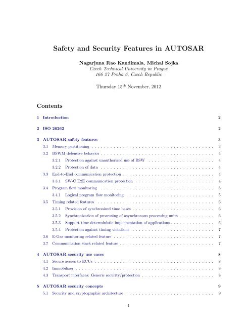
<strong>Safety</strong> <strong>and</strong> <strong>Security</strong> <strong>Features</strong> <strong>in</strong> <strong>AUTOSAR</strong><br />
Nagarjuna Rao K<strong>and</strong>imala, Michal Sojka<br />
Czech Technical University <strong>in</strong> Prague<br />
166 27 Praha 6, Czech Republic<br />
Thursday 15 th November, 2012<br />
Contents<br />
1 Introduction 2<br />
2 ISO 26262 2<br />
3 <strong>AUTOSAR</strong> safety features 3<br />
3.1 Memory partition<strong>in</strong>g . . . . . . . . . . . . . . . . . . . . . . . . . . . . . . . . . . . . . . . 3<br />
3.2 BSWM defensive behavior . . . . . . . . . . . . . . . . . . . . . . . . . . . . . . . . . . . . 4<br />
3.2.1 Protection aga<strong>in</strong>st unauthorized use of BSW . . . . . . . . . . . . . . . . . . . . . 4<br />
3.2.2 Protection of data . . . . . . . . . . . . . . . . . . . . . . . . . . . . . . . . . . . . 4<br />
3.3 End-to-End communication protection . . . . . . . . . . . . . . . . . . . . . . . . . . . . . 4<br />
3.3.1 SW-C E2E communication protection . . . . . . . . . . . . . . . . . . . . . . . . . 4<br />
3.4 Program flow monitor<strong>in</strong>g . . . . . . . . . . . . . . . . . . . . . . . . . . . . . . . . . . . . 5<br />
3.4.1 Logical program flow monitor<strong>in</strong>g . . . . . . . . . . . . . . . . . . . . . . . . . . . . 5<br />
3.5 Tim<strong>in</strong>g related features . . . . . . . . . . . . . . . . . . . . . . . . . . . . . . . . . . . . . 6<br />
3.5.1 Provision of synchronized time bases . . . . . . . . . . . . . . . . . . . . . . . . . . 6<br />
3.5.2 Synchronization of process<strong>in</strong>g of asynchronous process<strong>in</strong>g units . . . . . . . . . . . 6<br />
3.5.3 Support time determ<strong>in</strong>istic implementation of applications . . . . . . . . . . . . . . 6<br />
3.5.4 Protection aga<strong>in</strong>st tim<strong>in</strong>g violations . . . . . . . . . . . . . . . . . . . . . . . . . . 7<br />
3.6 E-Gas monitor<strong>in</strong>g related feature . . . . . . . . . . . . . . . . . . . . . . . . . . . . . . . . 7<br />
3.7 Communication stack related feature . . . . . . . . . . . . . . . . . . . . . . . . . . . . . . 7<br />
4 <strong>AUTOSAR</strong> security use cases 8<br />
4.1 Secure access to ECUs . . . . . . . . . . . . . . . . . . . . . . . . . . . . . . . . . . . . . . 8<br />
4.2 Immobilizer . . . . . . . . . . . . . . . . . . . . . . . . . . . . . . . . . . . . . . . . . . . . 8<br />
4.3 Transport <strong>in</strong>terfaces: Generic security/protection . . . . . . . . . . . . . . . . . . . . . . . 8<br />
5 <strong>AUTOSAR</strong> security concepts 9<br />
5.1 <strong>Security</strong> <strong>and</strong> cryptographic architecture . . . . . . . . . . . . . . . . . . . . . . . . . . . . 9<br />
1
5.2 Alarm clock concept . . . . . . . . . . . . . . . . . . . . . . . . . . . . . . . . . . . . . . . 9<br />
5.3 DCM manages security access level h<strong>and</strong>l<strong>in</strong>g . . . . . . . . . . . . . . . . . . . . . . . . . 10<br />
5.4 Format check<strong>in</strong>g of diagnostic services . . . . . . . . . . . . . . . . . . . . . . . . . . . . . 10<br />
5.5 NV block security of ECU reprogramm<strong>in</strong>g . . . . . . . . . . . . . . . . . . . . . . . . . . . 10<br />
5.6 Memory read access . . . . . . . . . . . . . . . . . . . . . . . . . . . . . . . . . . . . . . . 10<br />
Acronyms 12<br />
Glossary 13<br />
References 15<br />
1 Introduction<br />
Grow<strong>in</strong>g number of on-road vehicles <strong>in</strong>creases the need for safety <strong>and</strong> security of passengers, pedestrians<br />
<strong>and</strong> the vehicle itself. The new safety st<strong>and</strong>ard ISO 26262 [1] provides the basis for development of<br />
safety-related systems compris<strong>in</strong>g of electric, electronic <strong>and</strong> software components for road vehicles. The<br />
st<strong>and</strong>ard addresses generic concepts only <strong>and</strong> their implementation is up to the implementer of the<br />
developed component.<br />
AUTomotive Open System ARchitecture (<strong>AUTOSAR</strong>) 4.0 1 specifies many aspects of automotive systems<br />
development. Among others, it def<strong>in</strong>es concepts useful <strong>in</strong> development of safety related subsystems that<br />
comply with ISO 26262. It also def<strong>in</strong>es several security related concepts. As both automotive safety <strong>and</strong><br />
security is the doma<strong>in</strong> addressed by SESAMO project 2 , it is important to know what is supported by<br />
<strong>AUTOSAR</strong> <strong>and</strong> what is not. <strong>AUTOSAR</strong> is pretty big st<strong>and</strong>ard (it is published as a set of about 170<br />
PDF files) <strong>and</strong> it is not easy to look it up for concepts <strong>and</strong> features. For this reason, this document tries<br />
to summarize the safety <strong>and</strong> security related features (or concepts) specified <strong>in</strong> <strong>AUTOSAR</strong>.<br />
2 ISO 26262<br />
Before we start deal<strong>in</strong>g with <strong>AUTOSAR</strong> itself, we mention the <strong>in</strong>troductory requirements of ISO 26262<br />
[1] for functional safety of on-road vehicles.<br />
• ISO 26262 provides an automotive safety lifecycle (management, development, production, operation,<br />
service <strong>and</strong> decommission<strong>in</strong>g) <strong>and</strong> supports tailor<strong>in</strong>g the necessary activities dur<strong>in</strong>g these<br />
lifecycle phases.<br />
• ISO 26262 provides an automotive specific risk-based approach for determ<strong>in</strong><strong>in</strong>g Automotive <strong>Safety</strong><br />
Integrity Levels (ASILs).<br />
• ISO 26262 uses ASILs for specify<strong>in</strong>g the item’s necessary safety requirements for achiev<strong>in</strong>g an<br />
acceptable residual risk.<br />
• ISO 26262 provides requirements for validation <strong>and</strong> confirmation measures to ensure a sufficient<br />
<strong>and</strong> acceptable level of safety be<strong>in</strong>g achieved.<br />
• ISO 26262 provides requirements for the relation with suppliers.<br />
1 http://www.autosar.org<br />
2 http://sesamo-project.eu<br />
2
3 <strong>AUTOSAR</strong> safety features<br />
<strong>AUTOSAR</strong> provides a useful document [2] that summarizes requirements related to functional safety<br />
<strong>in</strong>troduced <strong>in</strong> the release 4.0 of <strong>AUTOSAR</strong>. This section is heavily based on this document.<br />
3.1 Memory partition<strong>in</strong>g<br />
This feature [3, BRF00115] is the extension of the Operat<strong>in</strong>g System (OS) <strong>and</strong> Run-Time Environment<br />
(RTE) functionality that enables the groups of Software Components (SW-Cs) to run <strong>in</strong> separate memory<br />
partitions <strong>in</strong> order to avoid <strong>in</strong>terference between them. It ensures that memory-related faults <strong>in</strong> a SW-C<br />
do not propagate to other SW-C’s. Additionally SW-C executed <strong>in</strong> user-mode has restricted access to<br />
CPU <strong>in</strong>structions that can change global CPU state [2].<br />
Components runn<strong>in</strong>g <strong>in</strong> a separate memory partition have to use <strong>in</strong>ter-OS-Application communication<br />
across boundaries of memory partitions, but this is not yet def<strong>in</strong>ed <strong>in</strong> <strong>AUTOSAR</strong>.<br />
Memory partition<strong>in</strong>g provides protection by means of restrict<strong>in</strong>g access to memory <strong>and</strong> memory-mapped<br />
hardware. In particular, code execut<strong>in</strong>g <strong>in</strong> one partition cannot modify memory of a different partition.<br />
Moreover, memory partition<strong>in</strong>g enables to protect read-only memory segments, as well as to protect<br />
memory-mapped hardware.<br />
Partition<strong>in</strong>g of BSW is not <strong>in</strong> the scope of the concept/feature – only SW-C is covered. These extensions<br />
are also useful for debugg<strong>in</strong>g <strong>and</strong> test<strong>in</strong>g of SW-Cs.<br />
Figure 1 shows an example of partition<strong>in</strong>g. Partitions are used as the fault conta<strong>in</strong>ment regions. When<br />
an error is detected <strong>in</strong> a particular partition then that partition can be term<strong>in</strong>ated or restarted dur<strong>in</strong>g<br />
run-time. These partitions are configured <strong>in</strong> Electronic Control Unit (ECU) configuration file. Let us<br />
consider a violation/error occurrence <strong>in</strong> the partition 1 of Figure 1, Partition 1 is then term<strong>in</strong>ated by<br />
the OS services <strong>and</strong> possible communication is stopped <strong>and</strong> the partition is restarted [4].<br />
Figure 1: Example of Partition<strong>in</strong>g (source [4])<br />
3
3.2 BSWM defensive behavior<br />
Basic Software Module (BSWM) defensive behavior prevents data corruption <strong>and</strong> wrong service calls <strong>in</strong><br />
the <strong>AUTOSAR</strong> Basic Software, this is achieved by the concepts described <strong>in</strong> the follow<strong>in</strong>g subsections.<br />
3.2.1 Protection aga<strong>in</strong>st unauthorized use of BSW<br />
<strong>AUTOSAR</strong> provides protection for BSWM from unauthorized use by SW-Cs <strong>and</strong> other BSWMs, to avoid<br />
SW-Cs from corrupt<strong>in</strong>g or <strong>in</strong>terfer<strong>in</strong>g with <strong>AUTOSAR</strong> service calls of safety-relevant SW-Cs <strong>and</strong> also<br />
to prevent non-safety related BSWMs from corrupt<strong>in</strong>g or <strong>in</strong>terfer<strong>in</strong>g with BSW used by safety-related<br />
BSWMs [3, BRF00128].<br />
Example use case for this concept: Only selected software modules are allowed to request the shutdown<br />
of ECU.<br />
3.2.2 Protection of data<br />
<strong>AUTOSAR</strong> protects safety-related data <strong>in</strong> RAM <strong>and</strong> non-volatile memory aga<strong>in</strong>st corruption (e.g. by<br />
us<strong>in</strong>g checksums) to h<strong>and</strong>le <strong>in</strong>ternal data <strong>in</strong> a safe manner [3, BRF00129].<br />
3.3 End-to-End communication protection<br />
In an embedded system the exchange of data between sender <strong>and</strong> receiver(s) can affect the functional<br />
safety if its functional safety depends on <strong>in</strong>tegrity of such data. Therefore such data are transmitted us<strong>in</strong>g<br />
mechanisms to protect them aga<strong>in</strong>st the effects of faults with<strong>in</strong> the communication l<strong>in</strong>k [2, Sec. 1.1.5].<br />
The End-to-End (E2E) communication protection related features are implemented <strong>in</strong> <strong>AUTOSAR</strong> 4.0<br />
as a st<strong>and</strong>ard library provid<strong>in</strong>g protection mechanisms that enable sender to protect such data <strong>and</strong> the<br />
receiver(s) to detect <strong>and</strong> h<strong>and</strong>le errors <strong>in</strong> the communication l<strong>in</strong>k at runtime. This library provides<br />
mechanisms for E2E protection, adequate for safety-related communication hav<strong>in</strong>g requirements up to<br />
ASIL D.<br />
SW-C end-to-end communication protection, described <strong>in</strong> the next section, aims to protect safety-related<br />
data exchange among SW-Cs [2].<br />
3.3.1 SW-C E2E communication protection<br />
This feature [3, BRF00114] helps SW-Cs located on remote ECUs to exchange safety-related data. Safe<br />
communication is possible by us<strong>in</strong>g extensions to RTE <strong>and</strong> ECU configuration file. This feature also<br />
helps to detect <strong>and</strong> tolerate faults <strong>in</strong> RTE, communication software <strong>and</strong> other BSWMs, as well as <strong>in</strong><br />
communication hardware.<br />
Logically, this feature creates a layer between Virtual Function Bus (VFB) <strong>and</strong> SW-Cs, which is realized<br />
by the follow<strong>in</strong>g means:<br />
• <strong>Safety</strong> protocol library – it is a set of stateless library functions that verify the communication<br />
(e.g. if a Cyclic Redundancy Check (CRC) of a message is correct or is it on time) <strong>and</strong> which are<br />
<strong>in</strong>voked by RTE or SW-Cs.<br />
• Introduction of additional configurable attributes (fields) for SW-C ports (e.g. port address), used<br />
by safety protocol library.<br />
The port attributes have the state <strong>in</strong>formation of the communication whereas the stateless library function<br />
does the checks. With these extensions any <strong>in</strong>ter-ECU communication can be possibly used to<br />
transmit safety related data. The safety protocol will work on any network/bus that is supported by<br />
<strong>AUTOSAR</strong>.<br />
4
Figure 2: Example of faults detected by E2E protection (source [4])<br />
The protocol needs to be configured depend<strong>in</strong>g on reliability <strong>and</strong> type of network used, size <strong>and</strong> criticality<br />
of transmitted data <strong>and</strong> fault tolerance of application. The configuration <strong>in</strong>volves selection of used<br />
mechanisms <strong>and</strong> mechanism strength (e.g. CRC8 or CRC16), the selection is done by the <strong>in</strong>tegrator.<br />
3.4 Program flow monitor<strong>in</strong>g<br />
Program flow monitor<strong>in</strong>g is a mechanism to check the correct execution of software. The focus of this<br />
concept is the detection of program flow errors, i.e. a divergence from the valid program sequence. An<br />
<strong>in</strong>correct program flow occurs if one or more program <strong>in</strong>structions are processed either <strong>in</strong> the <strong>in</strong>correct<br />
sequence, not <strong>in</strong> time or are not even processed at all. Program flow errors can for example lead to data<br />
corruption, data <strong>in</strong>consistencies or the SW failures [2, Sec. 1.1.1].<br />
Logical <strong>and</strong> temporal program flow monitor<strong>in</strong>g is used <strong>in</strong> the automotive <strong>in</strong>dustry <strong>and</strong> mentioned e.g.<br />
<strong>in</strong> ISO 26262 as a measure to detect failures of the process<strong>in</strong>g units <strong>and</strong> as measure for the detection of<br />
failures of the HW clock [2, Sec. 4.1.1].<br />
3.4.1 Logical program flow monitor<strong>in</strong>g<br />
Logical monitor<strong>in</strong>g of execution sequence of a program [3, BRF00131] enables the detection of errors<br />
that cause a divergence from valid program sequence dur<strong>in</strong>g the error-free execution of the application.<br />
The valid program sequences are identified <strong>and</strong> modeled dur<strong>in</strong>g design phase <strong>and</strong> the component for<br />
Logical Monitor<strong>in</strong>g of Program Sequence uses this model to supervise or monitor the proper execution<br />
of program sequences dur<strong>in</strong>g runtime. If any divergence is detected usually the system is reset.<br />
To reduce the overhead caused by logical monitor<strong>in</strong>g of program sequence, <strong>in</strong> <strong>AUTOSAR</strong> it is possible<br />
to restrict the def<strong>in</strong>ition of Supervised Entities (SE) to safety-related tasks/runnables. At least those<br />
have to be monitored but non safety-related tasks can be monitored as well.<br />
5
The logical program flow monitor<strong>in</strong>g of SW-Cs <strong>and</strong> Basic Software (BSW) modules is implemented by<br />
means of extension of watchdog manager.<br />
3.5 Tim<strong>in</strong>g related features<br />
Tim<strong>in</strong>g related features [2, Sec. 4.2] can be divided <strong>in</strong>to<br />
• provision of synchronized time bases,<br />
• synchronization of process<strong>in</strong>g of asynchronous process<strong>in</strong>g units,<br />
• support for time determ<strong>in</strong>istic implementation of applications <strong>and</strong><br />
• support for protection aga<strong>in</strong>st tim<strong>in</strong>g violations.<br />
Those <strong>in</strong>dividual groups are described <strong>in</strong> the follow<strong>in</strong>g subsections.<br />
3.5.1 Provision of synchronized time bases<br />
A synchronized time base is a SW time base exist<strong>in</strong>g at a process<strong>in</strong>g entity that is synchronized with SW<br />
time-bases at different process<strong>in</strong>g entities. A synchronized time-base can be achieved by time protocols<br />
or time agreement protocols that derive the synchronized time-base <strong>in</strong> a def<strong>in</strong>ed way from one or more<br />
physical time-bases. Examples are the Network Time Protocol (NTP) <strong>and</strong> FlexRay time agreement<br />
protocol [2, Sec. 4.2.1.1].<br />
Synchronization will apply to the clock rate <strong>and</strong> optionally apply to the clock absolute value.<br />
synchronized time bases are established by the synchronized time-base manager BSW module.<br />
Provision of synchronized time bases with<strong>in</strong> a cluster is restricted to FlexRay <strong>and</strong> TTCAN clusters <strong>in</strong><br />
<strong>AUTOSAR</strong> release 4.0 [3, BRF00120].<br />
<strong>AUTOSAR</strong> specifies to provide a service to access synchronized time bases available to BSWMs <strong>and</strong> SW-<br />
Cs, to enable SW-Cs to perform time-dependent actions <strong>and</strong> <strong>in</strong> particular synchronization & monitor<strong>in</strong>g<br />
[3, BRF00127].<br />
Possibility to synchronize <strong>AUTOSAR</strong> OS with global time from provid<strong>in</strong>g bus system <strong>in</strong> a well-def<strong>in</strong>ed<br />
<strong>and</strong> fast way, enabl<strong>in</strong>g applications to run their tasks synchronous to the global time from provid<strong>in</strong>g bus<br />
system [3, BRF00278].<br />
The<br />
3.5.2 Synchronization of process<strong>in</strong>g of asynchronous process<strong>in</strong>g units<br />
This concept is implemented to synchronize runnables with<strong>in</strong> a set of SW-Cs. They have to be attached<br />
to a synchronized RTE tim<strong>in</strong>g.<br />
Synchronization is possible with<strong>in</strong> a s<strong>in</strong>gle ECU as well as across networks [3, BRF00126].<br />
This feature is restricted to RTE tim<strong>in</strong>g events only. The events are used to trigger runnables. The<br />
synchronization of runnables that are controlled by different <strong>AUTOSAR</strong> OS <strong>in</strong>stances (e.g. if they are<br />
runn<strong>in</strong>g on different ECUs or different microcontrollers with<strong>in</strong> one ECU) is only possible if they are<br />
located on ECUs with<strong>in</strong> the same FlexRay or TTCAN network cluster.<br />
3.5.3 Support time determ<strong>in</strong>istic implementation of applications<br />
Time determ<strong>in</strong>istic implementation of applications requires to be able to specify tim<strong>in</strong>g constra<strong>in</strong>ts <strong>and</strong><br />
analyze tim<strong>in</strong>g properties at different stages of development, i.e. dur<strong>in</strong>g virtual <strong>in</strong>tegration on VFB<br />
level, development of SW-Cs <strong>and</strong> f<strong>in</strong>ally the <strong>in</strong>tegration of SW-C <strong>in</strong>to ECUs <strong>and</strong> of ECUs <strong>in</strong>to a system<br />
of ECUs [2].<br />
It shall be possibile to develop implementations based on <strong>AUTOSAR</strong> with verifiable tim<strong>in</strong>g constra<strong>in</strong>ts<br />
on jitter, latency <strong>and</strong> execution time. This requirement relates to task schedul<strong>in</strong>g, communication<br />
6
schedul<strong>in</strong>g <strong>and</strong> responsiveness to external events [3, BRF00122].<br />
<strong>AUTOSAR</strong> specifies to enable the use of external events as an <strong>in</strong>itiator for schedul<strong>in</strong>g. As certa<strong>in</strong> external<br />
events require a timely response to ensure correct behavior, these events must be able to <strong>in</strong>itiate tasks<br />
[3, BRF00123].<br />
3.5.4 Protection aga<strong>in</strong>st tim<strong>in</strong>g violations<br />
Depend<strong>in</strong>g on the Scalability Class, the <strong>AUTOSAR</strong> OS can provide protection mechanisms aga<strong>in</strong>st<br />
tim<strong>in</strong>g violation. As the OS is only aware of tasks <strong>and</strong> not of runnables, the OS provides protection<br />
mechanisms on the task level with the fault conta<strong>in</strong>ment region be<strong>in</strong>g the OS application.<br />
Tim<strong>in</strong>g protection of SW-Cs at runtime requires monitor<strong>in</strong>g of runnables <strong>and</strong> prevent<strong>in</strong>g the propagation<br />
of tim<strong>in</strong>g faults from one SW-C to another. If SW-Cs require protection from each other, then their<br />
runnables have to be placed <strong>in</strong>to different OS application, which implies that they are placed <strong>in</strong>to different<br />
task bodies.<br />
<strong>AUTOSAR</strong> specifies to provide statically configured runtime tim<strong>in</strong>g protection <strong>and</strong> monitor<strong>in</strong>g. This<br />
<strong>in</strong>cludes monitor<strong>in</strong>g that tasks are dispatched at the specified time, meet their execution time budgets<br />
<strong>and</strong> do not monopolize OS resources [3, BRF00121].<br />
<strong>AUTOSAR</strong> recommends to provide a mechanism that monitors ECU local time. This is a necessary<br />
basis for determ<strong>in</strong>istic execution of safety functions <strong>and</strong> for detection of failures of the system by safety<br />
<strong>in</strong>tegrity functions, with<strong>in</strong> the guaranteed time <strong>in</strong>tervals [3, BRF00125].<br />
3.6 E-Gas monitor<strong>in</strong>g related feature<br />
Electronic Gasol<strong>in</strong>e (E-Gas) monitor<strong>in</strong>g concept [5] is st<strong>and</strong>ardized by AKEGAS work<strong>in</strong>g group <strong>and</strong> is<br />
not a part of <strong>AUTOSAR</strong> st<strong>and</strong>ard, but still it is a st<strong>and</strong>ardized automotive safety concept.<br />
The E-Gas monitor<strong>in</strong>g related SW is located <strong>in</strong> a Complex Device Driver (CDD). The CDD allows direct<br />
access to the related <strong>in</strong>puts <strong>and</strong> outputs.<br />
If the responsibility of detection is placed <strong>in</strong> CDD, <strong>AUTOSAR</strong> BSW requires to provide a mechanism to<br />
transmit the communication protections aga<strong>in</strong>st a corruption or a loss of data to the CDD [2, BRF00243].<br />
Exclusive/Priority access to Serial Peripheral Interface Bus (SPI) bus should be granted to SW modules<br />
that carry out tim<strong>in</strong>g critical monitor<strong>in</strong>g protocols between the ma<strong>in</strong> controller <strong>and</strong> a monitor<strong>in</strong>g<br />
unit converted via SPI bus. This should be possible for both these SW modules be<strong>in</strong>g <strong>in</strong>cluded <strong>in</strong> an<br />
<strong>AUTOSAR</strong> SW-C, <strong>and</strong> these modules be<strong>in</strong>g <strong>in</strong>cluded <strong>in</strong> a complex device driver [3, BRF00251].<br />
<strong>AUTOSAR</strong> specifies to allow the use of mechanisms for the test<strong>in</strong>g <strong>and</strong> monitor<strong>in</strong>g of I/O HW elements<br />
as well as the safety related values received/transmitted us<strong>in</strong>g the I/O HW elements, to detect errors <strong>in</strong><br />
measured sensor data or output actuator data, <strong>and</strong> to detect failures <strong>in</strong> I/O HW [3, BRF00248].<br />
3.7 Communication stack related feature<br />
This feature aims at enhanc<strong>in</strong>g fault detection <strong>in</strong> order to cover communication failure modes <strong>and</strong> also<br />
provid<strong>in</strong>g possible recovery through redundancy [2]. The follow<strong>in</strong>g concepts are from [3].<br />
<strong>AUTOSAR</strong> specifies to provide mechanisms for data sequence control, enabl<strong>in</strong>g the possibility to check<br />
whether a signal is received <strong>in</strong> sequence [3, BRF00111]. For example, if a distributed safety related<br />
powertra<strong>in</strong> control system receives a torque request signal via CAN with a sequence counter with a<br />
value higher than expected, then this error is <strong>in</strong>terpreted as several messages are lost <strong>and</strong> there might<br />
be an <strong>in</strong>consistent state with<strong>in</strong> the powertra<strong>in</strong> system, <strong>in</strong> this case usually the powertra<strong>in</strong> system is<br />
re<strong>in</strong>itialized.<br />
<strong>AUTOSAR</strong> specifies to provide a mechanism that detects wrong rout<strong>in</strong>g <strong>and</strong> supports the correct rout<strong>in</strong>g<br />
7
of signals between SW-Cs, to detect when a signal is com<strong>in</strong>g from an unexpected SW-C sender or when<br />
provid<strong>in</strong>g the <strong>in</strong>formation that it is not supposed to provide. Such messages are reported as errors <strong>and</strong><br />
discarded. [3, BRF00112]<br />
<strong>AUTOSAR</strong> specifies to provide a mechanism that detects if periodic signals are not exchanged with<strong>in</strong><br />
def<strong>in</strong>ed time <strong>in</strong>terval. Timeouts are used to detect if communication system is function<strong>in</strong>g or if the<br />
<strong>in</strong>dividual ECU is communicat<strong>in</strong>g. [3, BRF00113]<br />
<strong>AUTOSAR</strong> specifies to support multiple communication l<strong>in</strong>ks, to tolerate faults on one of the channels.<br />
[3, BRF00241]<br />
<strong>AUTOSAR</strong> specifies to monitor network communication, to detect high-level issues with network communication<br />
<strong>and</strong> to <strong>in</strong>crease the fault detection capabilities of the system [3, BRF00242]<br />
4 <strong>AUTOSAR</strong> security use cases<br />
In this section some of the security use cases are documented.<br />
4.1 Secure access to ECUs<br />
<strong>AUTOSAR</strong> specifies to provide secure access to ECUs (e.g. by user authentication), <strong>in</strong>clud<strong>in</strong>g st<strong>and</strong>ardized<br />
up- <strong>and</strong> download of data <strong>and</strong> software. For this mechanisms <strong>and</strong> methods shall be def<strong>in</strong>ed [6,<br />
Ma<strong>in</strong>170].<br />
• The update <strong>and</strong> upgrade feasibility provided by <strong>AUTOSAR</strong> <strong>in</strong>cludes technical challenges (e.g.<br />
st<strong>and</strong>ardized up-/download protocol, partly update of the software) <strong>and</strong> mechanisms (e.g. authoriz<strong>in</strong>g<br />
the user)<br />
• To fulfill this requirement it is also necessary that the environment that is not st<strong>and</strong>ardized by<br />
<strong>AUTOSAR</strong> (like boot loader) needs to match the same security requirements.<br />
4.2 Immobilizer<br />
Immobilizer represents the anti-theft system, protect<strong>in</strong>g the vehicle from unauthorized driv<strong>in</strong>g. In case<br />
of any attempt for unauthorized eng<strong>in</strong>e start, immobilizer requests for visual <strong>and</strong> acoustical alarms to<br />
be generated.<br />
The core functionality of immobilizer is implemented with<strong>in</strong> immobilizer manager. It <strong>in</strong>corporates the<br />
basic functionalities like key learn<strong>in</strong>g, learnt key verification, immobilizer diagnostics etc. The data<br />
shared between these functionalities should be encrypted to ensure security operation. For further<br />
details on immobilizer, refer to [7, p. 77]<br />
4.3 Transport <strong>in</strong>terfaces: Generic security/protection<br />
Protection aga<strong>in</strong>st unauthorized access <strong>in</strong> production phase is absolutely required. In production phase<br />
Diagnostic Log <strong>and</strong> Trace (DLT) module shall use the security mechanisms provided by Diagnostic<br />
Communication Manager (DCM) to h<strong>and</strong>le the access to the log <strong>and</strong> trace messages. The mechanism is<br />
absolutely required to be implemented to permanently enable the communication module for test<strong>in</strong>g [8,<br />
BSW35000029].<br />
8
Figure 3: <strong>Security</strong> Application <strong>and</strong> Cryptographic rout<strong>in</strong>es (source [4])<br />
Figure 4: Separation of <strong>Security</strong> Application <strong>and</strong> Cryptographic rout<strong>in</strong>es (source [4])<br />
5 <strong>AUTOSAR</strong> security concepts<br />
5.1 <strong>Security</strong> <strong>and</strong> cryptographic architecture<br />
Each ma<strong>in</strong> security use case corresponds to a security application <strong>and</strong> each security application uses a<br />
different set of cryptographic services. The Crypto Service Manager (CSM) will make it possible for<br />
different applications to use the same service but us<strong>in</strong>g different underly<strong>in</strong>g cryptographic primitives <strong>and</strong><br />
cryptographic schemes/rout<strong>in</strong>es [9]. For example one application might need to use the hash service to<br />
compute an MD5 digest <strong>and</strong> another might need to compute an SHA1 digest as shown <strong>in</strong> Figure 3.<br />
Commonality of cryptographic rout<strong>in</strong>es may lead to slightly different crypto implementation or to duplicated<br />
code, due to which separation of security application <strong>and</strong> cryptographic rout<strong>in</strong>es is required.<br />
This is achieved by crypto module as shown <strong>in</strong> Figure 4.<br />
Crypto module manages requests for cryptographic services from applications <strong>and</strong> dispatches to a pool of<br />
cryptographic basic rout<strong>in</strong>es. To achieve this, crypto module exposes an <strong>in</strong>terface for security application<br />
to allow for a generic access to st<strong>and</strong>ardized cryptographic rout<strong>in</strong>es <strong>and</strong> an <strong>in</strong>terface for cryptographic<br />
rout<strong>in</strong>es to allow for arbitrary implementations to plug-<strong>in</strong> crypto module <strong>and</strong> for use by security applications,<br />
as shown <strong>in</strong> Figure 5.<br />
CSM will make it possible to configure which services are needed <strong>and</strong> to create several configurations<br />
for each service where schemes <strong>and</strong> primitives can be chosen. Figure 6 shows the embedd<strong>in</strong>g of crypto<br />
module. CSM is located <strong>in</strong> system services of service layer. Also shown is the support of Crytographic<br />
hardware, which is optional.<br />
5.2 Alarm clock concept<br />
Provides a real-time clock for wakeup purposes. SW-C can set or cancel wakeup alarms. Wakeup alarm<br />
allows them to leave a sleep state at a po<strong>in</strong>t <strong>in</strong> time <strong>in</strong> the future [3, BRF00196].<br />
9
Figure 5: Cryptographic Architecture (source [4])<br />
5.3 DCM manages security access level h<strong>and</strong>l<strong>in</strong>g<br />
The Diagnostic Communication Manager (DCM) is a basic software module that provides a common API<br />
for diagnostic services. The functionality of the DCM module is used by external diagnostic tools dur<strong>in</strong>g<br />
the development, manufactur<strong>in</strong>g or service. DCM module ensures diagnostic data flow <strong>and</strong> manages<br />
the diagnostic states, especially diagnostic sessions <strong>and</strong> security states. DCM software specification<br />
document [10] describes the functionality, the API, <strong>and</strong> the configuration of DCM.<br />
The DCM shall manage the h<strong>and</strong>l<strong>in</strong>g of the Unified Diagnostic Service (UDS) security access <strong>and</strong> also<br />
the security level h<strong>and</strong>l<strong>in</strong>g. The accessibility of the services (service identifier) <strong>in</strong> the actual security<br />
level shall be checked by the DCM [11, BSW04005].<br />
Some diagnostic services are <strong>in</strong> dependence to a security access level. Therefore it is necessary that the<br />
DCM has knowledge about the current level <strong>and</strong> no service that is restricted by security will be processed<br />
without authorization. Not all diagnostic services are allowed <strong>in</strong> each security level [11, BSW04005].<br />
5.4 Format check<strong>in</strong>g of diagnostic services<br />
The DCM absolutely requires to check the format of diagnostic service. An <strong>in</strong>correct service shall be<br />
rejected by a negative response, so that the application won’t get a request with <strong>in</strong>correct format [11,<br />
BSW04036].<br />
5.5 NV block security of ECU reprogramm<strong>in</strong>g<br />
After ECU reprogramm<strong>in</strong>g some Non-Volatile R<strong>and</strong>om Access Memory (NVRAM) data has to be kept<br />
secure. This means that some of the Non-Volatile memory blocks (NV blocks) <strong>in</strong> the NVRAM should<br />
never be erased nor be replaced with the default ROM data after first <strong>in</strong>itialization, for example immobilizer<br />
code or vehicle identification number [12, BSW08015].<br />
5.6 Memory read access<br />
The OS may offer support to protect the memory sections of an OS-Application aga<strong>in</strong>st read accesses<br />
by all other OS-Applications. If a task can read from any memory then it may operate on <strong>in</strong>correct<br />
data. This could result <strong>in</strong> failures at run time. Prevent<strong>in</strong>g read accesses provides a way of trapp<strong>in</strong>g such<br />
faults as soon as they occur. A secondary issue is security. While it is not anticipated that there are<br />
any security implications between OS-Applications on the same processor, read accesses does provide<br />
protection if required [13, BSW11000]<br />
10
Figure 6: Embedd<strong>in</strong>g of crypto module (source [4])<br />
11
Acronyms<br />
ASIL<br />
<strong>AUTOSAR</strong><br />
BSW<br />
BSWM<br />
CDD<br />
CRC<br />
CSM<br />
DCM<br />
DLT<br />
DSD<br />
DSL<br />
DSP<br />
E2E<br />
ECU<br />
E-Gas<br />
NV block<br />
NVRAM<br />
OS<br />
RTE<br />
SPI<br />
SW-C<br />
UDS<br />
VFB<br />
Automotive <strong>Safety</strong> Integrity Level<br />
AUTomotive Open System ARchitecture<br />
Basic Software<br />
Basic Software Module<br />
Complex Device Driver<br />
Cyclic Redundancy Check<br />
Crypto Service Manager<br />
Diagnostic Communication Manager<br />
Diagnostic Log <strong>and</strong> Trace<br />
Diagnostic Service Dispatcher<br />
Diagnostic Session Layer<br />
Diagnostic Service Process<strong>in</strong>g<br />
End-to-End<br />
Electronic Control Unit<br />
Electronic Gasol<strong>in</strong>e<br />
Non-Volatile memory block<br />
Non-Volatile R<strong>and</strong>om Access Memory<br />
Operat<strong>in</strong>g System<br />
Run-Time Environment<br />
Serial Peripheral Interface Bus<br />
Software Component<br />
Unified Diagnostic Service<br />
Virtual Function Bus<br />
12
Glossary<br />
Complex Device Driver<br />
Crypto Service Manager<br />
Diagnostic Communication Manager<br />
Diagnostic Log <strong>and</strong> Trace<br />
Diagnostic Service Dispatcher<br />
Diagnostic Session Layer<br />
Diagnostic Service Process<strong>in</strong>g<br />
Non-Volatile memory block<br />
OS-Application<br />
runnable<br />
An Atomic Software Component that on one<br />
side <strong>in</strong>terfaces with the VFB <strong>and</strong> on the<br />
other side directly accesses Peripheral Hardware<br />
<strong>and</strong>/or ECU-Abstraction <strong>and</strong>/or MCAL.<br />
Complex Driver can be accessed via <strong>AUTOSAR</strong><br />
Interfaces <strong>and</strong>/or directly by Basic Software<br />
Modules[14]<br />
It offers a st<strong>and</strong>ardized access to cryptographic<br />
services for applications <strong>and</strong> system functions.<br />
This module provides a common API for diagnostic<br />
services. The functionality of the DCM<br />
module is used by external diagnostic tools dur<strong>in</strong>g<br />
the development, manufactur<strong>in</strong>g or service.<br />
This module ensures diagnostic data flow <strong>and</strong><br />
manages the diagnostic states, especially diagnostic<br />
sessions <strong>and</strong> security states. Further<br />
refer[10]<br />
It is a Basic Software Module, which h<strong>and</strong>les<br />
<strong>and</strong> stores log <strong>and</strong> trace messages produced by<br />
SWC itself or the <strong>in</strong>teractions between SWC<br />
<strong>and</strong> RTE/VFB <strong>and</strong> by other Basic Sofware<br />
Modules. The log <strong>and</strong> trace messages are generated<br />
by call<strong>in</strong>g APIs provided by the DLT<br />
module[8]<br />
This is submodule of DCM <strong>and</strong> it processes a<br />
stream of diagnostic data. It receives a new diagnostic<br />
request over network <strong>and</strong> forwards it<br />
to a data processor <strong>and</strong> Transmits a diagnostic<br />
response over a network when triggered by the<br />
data processor. Further refer[10]<br />
This is a submodule of DCM <strong>and</strong> ensures<br />
data flow concern<strong>in</strong>g diagnostic requests <strong>and</strong> responses,<br />
supervises <strong>and</strong> guarantees diagnostic<br />
protocol tim<strong>in</strong>g <strong>and</strong> manages diagnostic states,<br />
especially diagnostic session <strong>and</strong> security. Further<br />
refer[10]<br />
This is a submodule of DCM <strong>and</strong> it h<strong>and</strong>les<br />
the actual diagnostic service requests. Further<br />
refer[10]<br />
the entire structure, which is needed to adm<strong>in</strong>istrate<br />
<strong>and</strong> to store a block of NV data.[12]<br />
A block of software <strong>in</strong>clud<strong>in</strong>g tasks, <strong>in</strong>terrupts,<br />
hooks <strong>and</strong> user services that form a cohesive<br />
functional unit<br />
Runnable entity<br />
13
unnable entity<br />
Scalability Class<br />
Virtual Function Bus<br />
A Runnable Entity is a part of an Atomic<br />
Software-Component which can be executed<br />
<strong>and</strong> scheduled <strong>in</strong>dependently from the other<br />
Runnable Entities of this Atomic Software-<br />
Component. It is described by a sequence of<br />
<strong>in</strong>structions that can be started by the glsRTE.<br />
Each runnable entity is associated with exactly<br />
one Entry Po<strong>in</strong>t.<br />
A group of features of the OS (like Memory Protection<br />
or Tim<strong>in</strong>g Protection) as def<strong>in</strong>ed <strong>in</strong> [15,<br />
Sec. 7.11].<br />
It is an abstraction of the communication between<br />
Atomic Software Components <strong>and</strong> AU-<br />
TOSAR Services. This abstraction is such that<br />
specification of the communication mechanisms<br />
is <strong>in</strong>dependent from the concrete technology<br />
chosen to realize the communication<br />
14
References<br />
[1] ISO26262, “ISO 26262 st<strong>and</strong>ard for functional safety of road vehicles,” Dec 2010.<br />
[2] <strong>AUTOSAR</strong>, “Technical safety concept status report,” Oct 2010, R4.0 rev 2. [Onl<strong>in</strong>e]. Available:<br />
http://www.autosar.org/download/R4.0/<strong>AUTOSAR</strong> TR <strong>Safety</strong>ConceptStatusReport.pdf<br />
[3] <strong>AUTOSAR</strong>, “Feature specification of the BSW architecture <strong>and</strong> the RTE,” Dec 2011,<br />
R4.0 rev 3. [Onl<strong>in</strong>e]. Available: http://www.autosar.org/download/R4.0/<strong>AUTOSAR</strong> RS<br />
BSWAndRTE<strong>Features</strong>.pdf<br />
[4] S. Bunzel, S. Furst, J. Wagenhuber, <strong>and</strong> F. Stappert, “<strong>Safety</strong> <strong>and</strong> security related features <strong>in</strong><br />
autosar,” June 2010. [Onl<strong>in</strong>e]. Available: http://www.automotive2010.de/programm/content data/<br />
Bunzel-<strong>AUTOSAR</strong>.pdf<br />
[5] E. W. Group, “St<strong>and</strong>ardized E-Gas monitor<strong>in</strong>g concept for eng<strong>in</strong>e management systems of<br />
gasol<strong>in</strong>e <strong>and</strong> diesel eng<strong>in</strong>es,” Jan 2007, r4.0. [Onl<strong>in</strong>e]. Available: http://wenku.baidu.com/view/<br />
aedb0922bcd126fff7050b51.html<br />
[6] <strong>AUTOSAR</strong>, “Ma<strong>in</strong> requirements,” Dec 2011, R4.0 rev 3. [Onl<strong>in</strong>e]. Available: http:<br />
//www.autosar.org/download/R4.0/<strong>AUTOSAR</strong> RS Ma<strong>in</strong>.pdf<br />
[7] <strong>AUTOSAR</strong>, “Explanation of application <strong>in</strong>terfaces of the body <strong>and</strong> comfort doma<strong>in</strong>,” Dec<br />
2011, R4.0 rev 3. [Onl<strong>in</strong>e]. Available: http://www.autosar.org/download/R4.0/<strong>AUTOSAR</strong> EXP<br />
AIBodyAndComfort.pdf<br />
[8] <strong>AUTOSAR</strong>, “Requirements on diagnostic log <strong>and</strong> trace,” Nov 2009, R4.0 rev 1. [Onl<strong>in</strong>e]. Available:<br />
http://www.autosar.org/download/R4.0/<strong>AUTOSAR</strong> SRS DiagnosticLogAndTrace.pdf<br />
[9] <strong>AUTOSAR</strong>, “Explanation of application <strong>in</strong>terfaces of the body <strong>and</strong> comfort doma<strong>in</strong>,” Nov<br />
2009, R4.0 rev 1. [Onl<strong>in</strong>e]. Available: http://www.autosar.org/download/R4.0/<strong>AUTOSAR</strong> SRS<br />
CryptoServiceManager.pdf<br />
[10] <strong>AUTOSAR</strong>, “Specification of diagnostic communication manager,” Sep 2010, R4,<br />
rev 3. [Onl<strong>in</strong>e]. Available: http://www.autosar.org/download/R4.0/<strong>AUTOSAR</strong> SWS<br />
DiagnosticCommunicationManager.pdf<br />
[11] <strong>AUTOSAR</strong>, “Requirements on diagnostic,” Dec 2011, R4.0, rev 3. [Onl<strong>in</strong>e]. Available:<br />
http://www.autosar.org/download/R4.0/<strong>AUTOSAR</strong> SRS Diagnostic.pdf<br />
[12] <strong>AUTOSAR</strong>, “Requirements on memory services,” Dec 2009, R4.0 rev 1. [Onl<strong>in</strong>e]. Available:<br />
http://www.autosar.org/download/R4.0/<strong>AUTOSAR</strong> SRS MemoryServices.pdf<br />
[13] <strong>AUTOSAR</strong>, “Requirements on operat<strong>in</strong>g system,” Oct 2011, R4.0 rev 3. [Onl<strong>in</strong>e]. Available:<br />
http://www.autosar.org/download/R4.0/<strong>AUTOSAR</strong> SRS OS.pdf<br />
[14] <strong>AUTOSAR</strong>, “Glossary,” Dec 2011, R4 rev 3. [Onl<strong>in</strong>e]. Available: http://www.autosar.org/<br />
download/R4.0/<strong>AUTOSAR</strong> TR Glossary.pdf<br />
[15] <strong>AUTOSAR</strong>, “Specification of operat<strong>in</strong>g system,” Nov 2011, R4.0 rev 3. [Onl<strong>in</strong>e]. Available:<br />
http://www.autosar.org/download/R4.0/<strong>AUTOSAR</strong> SWS OS.pdf<br />
15