Direct Drive Brushless Servo Systems
Catalog 8000-3
Catalog 8000-3

You also want an ePaper? Increase the reach of your titles
YUMPU automatically turns print PDFs into web optimized ePapers that Google loves.
Catalog 8000-3/USA<br />
Dynaserv Series<br />
DYNASERV<br />
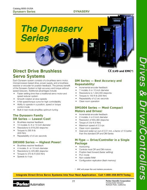
<strong>Direct</strong> <strong>Drive</strong> <strong>Brushless</strong><br />
<strong>Servo</strong> <strong>Systems</strong><br />
Each Dynaserv system consists of a brushless servo motor,<br />
microprocessor-based drive, power supply, and a brushless<br />
resolver or encoder for position feedback. The primary benefit<br />
of the Dynaserv System is high accuracy and torque without<br />
speed reducers. Additional advantages include:<br />
• Faster settling time than a traditional servo motor and<br />
speed reducer system<br />
• Smooth rotation at slow speeds<br />
• A flat speed/torque curve for high controllability<br />
• Ability to operate in a position, speed or torque<br />
control mode<br />
• Built-in test mode simplifies optimum tuning<br />
The Dynaserv Family<br />
DR Series — Lowest Cost!<br />
• <strong>Brushless</strong> resolver feedback<br />
• 13 models; 6, 8 or 10 inch diameter<br />
• Resolutions to 819,200 steps/rev<br />
• Torques to 295 ft-lb<br />
(400 Nm)<br />
• Repeatability of ±5 arc seconds<br />
DR5000 Series — Highest Power!<br />
• <strong>Brushless</strong> resolver feedback<br />
• 4 models, 6- or 10-inch diameter<br />
• Resolutions to 425,984 steps/rev<br />
• Torques to 370 lb-ft (500 Nm)<br />
• Speeds to 4 rps<br />
DM Series — Best Accuracy and<br />
Repeatability!<br />
• Incremental encoder feedback<br />
• 7 models; 6 or 10 inch diameter<br />
• Resolutions to 1,024,000 steps/rev<br />
• Torques to 150 ft-lb (200 Nm)<br />
• Repeatability of ±2 arc seconds<br />
• Clean room operation<br />
(LVD and EMC*)<br />
DM1004 Series — Most Compact<br />
Motors and <strong>Drive</strong>s!<br />
• Incremental encoder feedback<br />
• 2 models; 4 or 6 inch diameter<br />
• Resolution of 655,360 steps/rev<br />
• Torque of 3 lb-ft (4 Nm)<br />
• Maximum speed of 2.5 rps<br />
• Clean room operation<br />
• Axial and radial run-out of 0.01 mm, a factor of 10 better<br />
than the standard DR and DM Series<br />
M-Type — <strong>Drive</strong>/Controller in a Single<br />
Package<br />
• Autotuning<br />
• Controls most DR and DM motors<br />
• Position feed forward (faster settling)<br />
• PLC mode<br />
• Non-volatile RAM<br />
• Configuration replication (flash memory)<br />
B<br />
* EMC with proper filter and intallation procedures.<br />
Integrate <strong>Direct</strong> <strong>Drive</strong> <strong>Servo</strong> <strong>Systems</strong> Into Your Next Application. Call 1-800-358-9070 Today.<br />
Automation<br />
77 Parker Hannifin Corporation<br />
Compumotor Division<br />
Rohnert Park, California
Catalog 8000-3/USA<br />
Introduction<br />
The Dynaserv System Allows the User to<br />
Operate in One of Three Modes of Control:<br />
Position control – up to 1,024,000 steps/rev<br />
Speed control – ±10V Velocity command input<br />
Torque control – stable response at ±8V input<br />
This type of flexibility combined with a high torque/weight<br />
ratio, high accuracy, faster settling times, high torque at high<br />
speed, smooth rotation, optimum tuning and clean operation all<br />
add up to cost effective high performance alternative to the<br />
traditional motor and speed reducer combinations.<br />
High Torque/Weight Ratio<br />
The Dynaserv motors are designed with a permanent magnet<br />
constructed of rare-earth materials located at the center of the<br />
stator core.<br />
Max. Torque x Rated Speed Power (W)<br />
5000<br />
2000<br />
1000<br />
500<br />
200<br />
100<br />
50<br />
20<br />
Torque (Power)/Weight Comparison<br />
+<br />
+ +<br />
+<br />
DYNASERV<br />
10<br />
2 4 10 20 42 108 216<br />
Weight (lbs)<br />
+ +<br />
+<br />
DC/AC <strong>Servo</strong> Actuator (with Speed Reducer)<br />
Power/Weight Comparison<br />
High Precision<br />
Dynaserv motors eliminate the backlash or hysteresis inevitable<br />
in using any speed reducer. Absolute positioning of 30 arc-sec<br />
is typical with a repeatability of ±2 arc-sec.<br />
Faster Settling Time<br />
The Dynaserv system reduces machine cycle times by decreasing<br />
settling times. This result is realized because of the<br />
"gearless" design and sophisticated "I-PD" control algorithm.<br />
DYNASERV<br />
High Torque at High Speed<br />
The torque/speed curve of the various Dynaserv models is very<br />
flat. This results in high acceleration at high speeds (4.0 rps)<br />
with good controllability.<br />
Smooth Rotation<br />
The very low velocity and torque ripple of the Dynaserv<br />
contribute to its excellent speed controllability.<br />
Ripple (%)<br />
15<br />
10<br />
5<br />
3<br />
Speed Ripple<br />
(DM1150A)<br />
Conditions<br />
• Load 30 x Rotor Inertia<br />
• Rotation: CW<br />
• Speed Mode<br />
0.2 0.4 0.6 0.8 1.0 1.2<br />
Revolution (rps)<br />
Dynaserv Velocity/Torque Ripple<br />
Optimum Tuning<br />
Dynaserv systems offer the user a tuning mode that simplifies<br />
the setting of optimum parameters for the actual load. Turning<br />
on the "test" switch on the front panel of the drive produces a<br />
test signal. Utilizing an oscilloscope the gain settings are quickly<br />
optimized by adjusting the digital switches and potentiometers<br />
on the front panel.<br />
Clean Opearation<br />
The Dynaserv system is brushless and gearless which results in<br />
a maintenance-free operation. With preparation, the DM Series<br />
can operate in Class 10 environments.<br />
Measured by:<br />
Made by:<br />
Source:<br />
Min. Resolution:<br />
Sampling:<br />
20<br />
15.3<br />
15<br />
14.7<br />
Torque (N • m)<br />
5<br />
0<br />
0°<br />
Torque Ripple<br />
(DM1015A)<br />
90° 180° 270° 360°<br />
Rotational Angle (deg.)<br />
LPC-101 Particle Counter<br />
PMS Corp.<br />
He-Ne Lazor Light<br />
0.1 micro meter (Particle Diameter)<br />
0.1 Cubic feet/min.<br />
5%<br />
Distance<br />
Distance<br />
VERTICAL 5 AXES ROBOT<br />
(µm)<br />
Using Traditional Motors/Reducers<br />
100<br />
50<br />
0<br />
-20<br />
Time (sec.)<br />
-50<br />
-100<br />
0.25 0.8 Settling Time<br />
Travel Time<br />
(µm)<br />
SCARA 4 AXES ROBOT<br />
100<br />
Using “DYNASERV”<br />
50<br />
0<br />
Time (sec.)<br />
-20<br />
-50 0.2 0.2<br />
Settling Time<br />
-100<br />
Travel Time<br />
Settling Time comparison in Robot Application<br />
COUNT (Count/ft • min)<br />
3<br />
50<br />
30<br />
10<br />
0<br />
0 0.3 0.5 0.8<br />
Diameter (µm)<br />
Dust from Dynaserv (DM1045B)<br />
Automation<br />
78 Parker Hannifin Corporation<br />
Compumotor Division<br />
Rohnert Park, California
Catalog 8000-3/USA<br />
Introduction<br />
DYNASERV<br />
The Dynaserv has provided solutions to a variety<br />
of applications such as:<br />
Assembly<br />
• Base machine<br />
• Pick and place<br />
• Inserter/mounter<br />
Robots<br />
• Handling<br />
• Clean room<br />
• Universal<br />
Transport<br />
• Turn table<br />
• Belt conveyor<br />
• Three-dimensional<br />
warehouse<br />
Inspection and Measuring<br />
• Three dimensional<br />
measuring<br />
• Goniometer<br />
• Non-destructive x-ray<br />
Work<br />
• Machining center work<br />
table<br />
• Press roll feed<br />
• Grinder table<br />
Commercial<br />
• Printing machines<br />
• Medical equipment<br />
• Follow-up equipment<br />
Material Handling<br />
By attaching a small arm or linkage to the Dynaserv, very high<br />
velocities can be attained. This type of design has been used<br />
on a wide variety of equipment, such as a chip mounting<br />
machine. On this machine accuracies of 30 arc-sec are<br />
maintained with very high arm speed.<br />
Dynaserv motor for arm<br />
Dynaserv motor<br />
for X axis<br />
Indexing/Rotary Positioning<br />
The Dynaserv has high accelerations lending itself to high<br />
speed point-to-point positioning applications requiring low<br />
cycle time. In scanning and inspection applications the<br />
outstanding low speed performance will be of merit.<br />
Rotary table for assembly<br />
Tool turret<br />
Robotics<br />
Dynaserv direct drive motors were first developed to drive<br />
SCARA (Selective Compliance Assembly Robot Arm) in<br />
applications requiring repetitive and physically taxing<br />
operations.<br />
B<br />
Printed<br />
circuit board<br />
Feeder<br />
Feed-to-Length<br />
The Dynaserv system eliminates the need for gear reduction<br />
and allows for direct control of the nip roll in most feed-tolength<br />
applications. The ability to effectively control loads up to<br />
100 times its own rotor inertia allows the Dynaserv to be<br />
applied in a variety of machines. The net result of specifying a<br />
Dynaserv system is increased repeatability of the feed material.<br />
SCARA robot<br />
for assembly<br />
Peripherals for robot<br />
Roll Feeder<br />
Integrate <strong>Direct</strong> <strong>Drive</strong> <strong>Servo</strong> <strong>Systems</strong> Into Your Next Application. Call 1-800-358-9070 Today.<br />
Automation<br />
79 Parker Hannifin Corporation<br />
Compumotor Division<br />
Rohnert Park, California
Catalog 8000-3/USA<br />
Introduction<br />
DYNASERV<br />
Motor Construction and Operation<br />
The torque is proportional to the square of the sum of the bias<br />
magnetic flux Øm, due to the permanent magnet and the<br />
excitation magnetic flux of windings.<br />
T oc (φm + φc) 2<br />
High torque is generated due to the following factors. First,<br />
the motor diameter is large. The tangential forces between<br />
rotor and stator act at a large radius, resulting in higher torque.<br />
Secondly, a large number of small rotor and stator teeth create<br />
many magnetic cycles per motor revolution. More working<br />
cycles means increased torque.<br />
<strong>Direct</strong> drive systems couple the load of the system directly to<br />
the motor without the use of belts or gears. Most servo motors,<br />
brushed or brushlesss, often lack adequate torque or resolution<br />
to satisfy application needs. Therefore, mechanical means,<br />
such as gear reduction systems are implemented to meet<br />
system requirements. The Dynaserv can provide very high<br />
torque in a modest package size and solve many of the<br />
performance issues of the gear reducer. All this in a system that<br />
is as easy to use as a stepping motor.<br />
The figure below shows the construction of the Dynaserv DM<br />
Series direct drive motor compared to a conventional motor<br />
with a gear reducer. As shown in the figure, the gear reducer<br />
relies on frictional contact to reduce the speed of the load. This<br />
gearing effectively increases torque and resolution but sacrifices<br />
speed and accuracy. The direct drive motor is brushless<br />
and gearless so it eliminates friction from its power transmission.<br />
Since the feedback element is coupled directly to the<br />
load, system accuracy and repeatability are greatly increased<br />
and backlash is eliminated.<br />
Conventional Motor/Gear Reducer vs. Dynaserv<br />
Gear reducer<br />
DM Series<br />
Encoder<br />
DC/AC motor<br />
Encoder PCB<br />
Slit plate<br />
Stator<br />
element<br />
Rotor core<br />
Bearing<br />
Rotating<br />
element<br />
Stator core<br />
Gear Reducer System Limitations<br />
• Backlash limits positional accuracy<br />
• Gearing causes a trade-off between speed and resolution<br />
• Inefficiently transfers torque<br />
Magnetic Circuit<br />
Hub<br />
Rotor<br />
Stator A<br />
Φ m<br />
Excitation<br />
coil<br />
Permanent<br />
magnet<br />
Stator B<br />
Exploded View of the Dynaserv Motor Model DM<br />
Rotor core<br />
Stator core<br />
Retaining<br />
ring<br />
Core<br />
Housing kit<br />
Φ c<br />
Clamp ring<br />
T<br />
Φ m<br />
Encoder plate<br />
LED kit<br />
Housing<br />
PDA kit<br />
Encoder<br />
• Friction introduces inaccuracies and non-linearities<br />
• Gearing reduces stiffness at the load<br />
The motor contains precision bearings, magnetic components<br />
and integral feedback in a compact motor package. The motor<br />
is an outer rotor type, providing direct motion of the outside<br />
housing of the motor and thus the load. The cross roller<br />
bearings which support the rotor have high stiffness, to allow<br />
the motor to be connected directly to the load. In most cases is<br />
is not necessary to use additional bearings or connecting<br />
shafts.<br />
Automation<br />
80 Parker Hannifin Corporation<br />
Compumotor Division<br />
Rohnert Park, California
Catalog 8000-3/USA<br />
Introduction<br />
Selecting your Dynaserv<br />
The normal principals of servo motor sizing apply to the<br />
Dynaserv, but there are a few special considerations to keep in<br />
mind.<br />
DYNASERV<br />
Peak Torque/Continuous Torque<br />
The speed torque curves in this section represent the peak<br />
available torque. Continuous torques are approximately 2/3 of<br />
the peak value.<br />
lb-ft<br />
296<br />
259<br />
222<br />
DR1400A<br />
DR-A Series – 115 volts<br />
(N-m)<br />
(400)<br />
(350)<br />
(300)<br />
Torque<br />
185<br />
148<br />
DR1200A<br />
DR1300A<br />
(250)<br />
(200)<br />
111<br />
(150)<br />
74<br />
DR1100A<br />
(100)<br />
37<br />
(50)<br />
0<br />
0<br />
0 0.5 1.0 1.5 2.0<br />
Speed-RPS<br />
Inertia Matching<br />
When selecting the right Dynaserv for your application, the<br />
inertia match between the motor and load is a critical factor.<br />
The specifications listed in this section are for a 30:1 load to<br />
rotor inertia ratio. The following table lists the recommended<br />
ratios for specific application types. Actual results will depend<br />
highly on the usage, so these values are just for reference<br />
purposes. It is always a good idea to add 30-50% safety<br />
margin in sizing calculations.<br />
Application Types and Ratios<br />
Max K Ratio<br />
Application Type (J load<br />
/J motor<br />
)<br />
High throughput applications 5-10<br />
(printing machines, chip mounting)<br />
General high speed applications 20-30<br />
(SCARA robot, transfer arms)<br />
B<br />
High speed but balanced load 50-100<br />
applications<br />
(Rotary Index, Rotary Tables)<br />
High accuracy, slow speed 100-200<br />
applications<br />
(Measuring Equipment)<br />
Model Types<br />
When selecting the model type, the decision comes down to a<br />
trade-off of resolution, accuracy, speed, and cost. Please use<br />
this table to match your specific application requirements to the<br />
correct direct drive motor. Keep in mind that these ratings are<br />
speculative and based only on the features of these three<br />
models. i.e. The lowest accuracy Dynaserv is still very accurate<br />
by normal motor standards.<br />
Model Types<br />
DM DR DR5000<br />
Series Series Series<br />
Power Lowest Medium Highest<br />
Accuracy Highest Medium Lowest<br />
Motor Weight Lowest Medium Highest<br />
Resolution Highest Medium Lowest<br />
Cost Medium Lowest Highest<br />
Speed Lowest Medium Highest<br />
Integrate <strong>Direct</strong> <strong>Drive</strong> <strong>Servo</strong> <strong>Systems</strong> Into Your Next Application. Call 1-800-358-9070 Today.<br />
Automation<br />
81 Parker Hannifin Corporation<br />
Compumotor Division<br />
Rohnert Park, California
Catalog 8000-3/USA<br />
Introduction<br />
DYNASERV<br />
Application Considerations for using the<br />
Dynaserv <strong>Direct</strong> <strong>Drive</strong> <strong>Brushless</strong> <strong>Servo</strong> <strong>Systems</strong><br />
Sizing and Selection Considerations<br />
• All Speed vs. Torque curves shown in Compumotor’s<br />
Catalog and Dynaserv User Guide show peak torque.<br />
Use two-thirds of peak torque to calculate the available<br />
continuous torque.<br />
• If you require more than two-thirds of peak torque for short<br />
periods of time (low duty cycle applications), calculate<br />
RMS (room mean square) torque. make sure RMS torque<br />
is less than 2/3 of peak torque.<br />
• Friction torque should not exceed 30% of a motor’s peak<br />
torque.<br />
• Dynaservs operate most efficiently with a balanced load.<br />
Overhung loads cannot exceed 148 ft-lbs for the DR-B<br />
and DM-B series motors. Overhung loads cannot eceed<br />
295 ft-lbs for DR-E, DR-A and DM-A series motors. These<br />
values should be derated by 33% for constant loads and<br />
80–90% for intermittent loads (fatigue) to incoroprate a<br />
safety margin.<br />
• Always calculate the load-to-rotor inertia ratio before<br />
selecting a motor. The acceptable ratio is applicationand<br />
motor-dependent. Applications requiring low cycle<br />
times and high accelerations need a lower ratio than slowspeed,<br />
continuous velocity applications. Refer to the<br />
acceptable inertia values for different application types on<br />
the previous page.<br />
Cabling Considerations<br />
• The Dynaserv is not shipped with a power cable. This<br />
cable must be provided by the end user. The Dynaserv is<br />
shipped with a 50-pin Honda connector. Use this connector<br />
to construct a cable between the Indexer, <strong>Servo</strong><br />
controller, or other input/output devices. Prefabricated<br />
cables for Compumotor indexers and servo controllers are<br />
available.<br />
• The motor and feedback cables cannot exceed 30 meters<br />
in length.<br />
Mounting and Environmental Considerations<br />
• Do not drill holes into the Dynaserv motor.<br />
• The Dynaserv is an outer rotor motor. The rotating load<br />
must be mounted to the upper mounting surface (the<br />
rotor). The lower stator surface must be mounted to the<br />
rigid and stationary machine base.<br />
• Install the motor in an appropriate location as the motor is<br />
not dust proof, watertight, or oil proof.<br />
Axial Compression<br />
and Tension Load Limits<br />
Compression<br />
Tension<br />
DR-B Series 6744 lbs 2248 lbs<br />
DR-E, DR-A 8992 lbs 4496 lbs<br />
DM-B 6600 lbs 2200 lbs<br />
DM-A 8800 lbs 4400 lbs<br />
These limits should be derated to incorporate a safety<br />
margin. If the load is intermittent and repetitive, derate these<br />
values by 80–90%.<br />
• If the motor is used with oscillating rotation movements<br />
with a small angle (50º or less), then perform a running-in<br />
operation with back-and-forth movements about 10 times,<br />
each move exceeding an angle of at least 90º. The<br />
running-in operation must be carried out every 10,000<br />
times of back-and-forth oscillation movements in order to<br />
ensure proper lubrication of the bearings.<br />
Automation<br />
82 Parker Hannifin Corporation<br />
Compumotor Division<br />
Rohnert Park, California
Catalog 8000-3/USA<br />
Introduction<br />
LED Diagnostics<br />
A seven-segment LED is mounted on the front panel of both<br />
the DR and DM Series drives to display the normal/abnormal<br />
status of the motor and drive. The following is a summary of the<br />
display codes.<br />
DYNASERV<br />
Normal status<br />
<strong>Servo</strong> Off<br />
Normal status<br />
<strong>Servo</strong> On<br />
Overspeed warning<br />
<strong>Servo</strong> Off<br />
Overspeed warning<br />
<strong>Servo</strong> On<br />
RAM Error<br />
(<strong>Drive</strong> in need of repair)<br />
Encoder Error—not receiving pulses<br />
Check cabling, encoder malfunction<br />
Control power supply error<br />
Connect problem (may need repair)<br />
Counter overflow warning—position error is<br />
greater than 32,768 steps<br />
<strong>Servo</strong> Compensation<br />
ROM Error<br />
(<strong>Drive</strong> in need of repair)<br />
Characteristic<br />
Frequency<br />
Integral Limitter<br />
Test On<br />
Switch Off<br />
DC Gain<br />
AC Gain<br />
Characteristic<br />
Frequency<br />
(6-20Hz)<br />
DC Gain<br />
Before Adjusting<br />
Integral<br />
Limitter<br />
Main power supply failure—burnt fuse<br />
Check cabling, power and fuse<br />
CPU Stop<br />
(<strong>Drive</strong> in need of repair)<br />
B<br />
Monitor<br />
Terminal<br />
Speed<br />
Position<br />
Ground<br />
Optimized Wave Form<br />
Watchdog timer error—illegal interrupt,<br />
computation overflow<br />
Synchro-scope<br />
Power amp error—overvoltage, motor short<br />
phase-to-phase or phase-to-ground<br />
Overload condition<br />
Average current exceeded.<br />
<strong>Servo</strong> systems require adjustment to optimize the motor<br />
performance in the specific system environment. Tuning the<br />
Dynaserv while in the position control mode, requires the<br />
adjustment of just three parameters.<br />
The position control system is adjusted while in the Test<br />
Mode with the actual load attached to the motor. Turning on<br />
the test switch at the front panel causes the drive to generate a<br />
2.5 Hz square wave position signal. The actual motor position<br />
can be monitored by connecting a scope to the position<br />
monitor output on the front panel. As in the figure, the tuning<br />
parameters are adjusted until the waveform is optimized. After<br />
the tuning is complete, turn off the test switch and the system<br />
is ready for operation. If a scope is not available there is a<br />
procedure for tuning without a scope in the system user guide.<br />
Characteristic Frequency (fc)<br />
The value of this switch represents system bandwidth. This gain<br />
will effect rise time and system responsiveness. Too large a<br />
value will cause excessive overshoot and ringing, while too<br />
small a value will result in a sluggish, unresponsive system.<br />
Integral Limiter (ILIM)<br />
The value of this switch represents the limit of the digital<br />
integrator during servo compensation. The larger the switch<br />
setting, the larger the limited value. With a smaller limited value<br />
the settling time will be decreased, but if the setting is too low,<br />
the motor output torque is limited.<br />
DC Gain (DC)<br />
This variable resistor sets the DC Gain adjustment from 0.5 to<br />
110. The DC Gain should be set as high as possible without<br />
causing the system to go unstable. The DC Gain will help<br />
dampen out ringing and over-shoot.<br />
Integrate <strong>Direct</strong> <strong>Drive</strong> <strong>Servo</strong> <strong>Systems</strong> Into Your Next Application. Call 1-800-358-9070 Today.<br />
Automation<br />
83 Parker Hannifin Corporation<br />
Compumotor Division<br />
Rohnert Park, California
Catalog 8000-3/USA<br />
DR Series<br />
DYNASERV<br />
<strong>Direct</strong> <strong>Drive</strong><br />
<strong>Brushless</strong><br />
<strong>Servo</strong> <strong>Systems</strong><br />
The Dynaserv DR Series provides the user with a high performance<br />
direct drive servo system with resolver feedback. Each<br />
of the thirteen models includes a direct drive motor, integral<br />
resolver, microprocessor based drive and a 10 foot motor-todrive<br />
cable.<br />
The DR Series motor is brushless and without gears allowing<br />
for long, maintenance-free operation. The cross roller bearing<br />
design can support up to 4 tons of compression load and 295<br />
ft-lbs of overhung load. The center hole in the motor is up to 6<br />
inches in diameter and can be used to simplify system wiring.<br />
The user can elect to operate the DR Series in either a<br />
position, velocity or torque mode. In the position mode, the<br />
drive accepts step and direction input from any Compumotor<br />
indexer or user-supplied pulse source. Operating in the velocity<br />
mode requires a ±10VDC input and torque mode requires a<br />
±8VDC input.<br />
High performance closed loop operation is obtained with a<br />
sophisticated I-PD digital and analog control algorithm. The<br />
analog velocity loop provides high bandwidth for excellent<br />
system response. The digital position loop simplifies position<br />
control and optimizes system accuracy.<br />
A built-in test mode and position/velocity monitors allow for<br />
convenient and efficient tuning.<br />
The DR <strong>Drive</strong> is fully protected against open and short<br />
circuits, overcurrent, overvoltage and overtemperature. A seven<br />
segment LED indicator provide the user with the status and<br />
diagnostic information from the front panel.<br />
Features<br />
• <strong>Brushless</strong> direct drive motor with 10 foot cable<br />
• 13 models available in 6 or 10 inch diameters<br />
• Resolver feedback<br />
• Torques to 295 ft-lbs (400 Nm)<br />
• Resolutions to 819,200 steps/rev<br />
• Supports 4 tons of compression load<br />
• Microprocessor control of I-PD control algorithm<br />
(LVD and EMC*)<br />
• Analog velocity loop/digital position loop<br />
• Built-in test mode for easy tuning<br />
• Diagnostic LED display<br />
• Step and direction input/position control<br />
• ±10V input/torque or velocity control<br />
• Gain settings can be changed “on the fly”<br />
• Configurable position accuracy to reduce system settling<br />
time<br />
• Complete system, ready for operation<br />
Accessories<br />
• Compumotor Controllers<br />
The Dynaserv is compatible with all Compumotor<br />
controllers.<br />
• Bases<br />
Mounting bases to simplify mounting to a flat surface (DR-<br />
B Series only).<br />
• Dynamic Braking<br />
Capacitor type or Speed-switching type for each motor<br />
size.<br />
• Precision Machining<br />
Axial and radial run-out of .01, .02 or .005 mm is available<br />
on most Dynaserv models. Standard axial and radial runout<br />
for all motors is 0.1 mm.<br />
• Mechanical Braking<br />
Most motors can be ordered with mechanical brakes for<br />
power down, or emergency use. Not available with DR-<br />
1008B and DR-E series.<br />
• Line Filters for CE installations<br />
• Interface cables for use with Compumotor's 6K and 6000<br />
Series controllers<br />
* EMC with proper filter and intallation procedures.<br />
Automation<br />
84 Parker Hannifin Corporation<br />
Compumotor Division<br />
Rohnert Park, California
Catalog 8000-3/USA<br />
DR Series<br />
DYNASERV<br />
Specifications<br />
Parameter<br />
Value<br />
Performance Repeatability ±5 arc-sec (0.00139°)<br />
Accuracy<br />
±30 arc-sec (0.0083°) DRA Series<br />
±45 arc-sec (0.0125°) DRB, DRE Series<br />
Max stepping rate<br />
1,600,000 steps/sec<br />
Power Volts 115VAC 1-phase, or 230VAC 1-phase, 50/60 #2<br />
Range +10% to -15%<br />
Current<br />
20 amps max<br />
Inputs<br />
Command interface<br />
• Step input<br />
• <strong>Direct</strong>ion<br />
Analog input<br />
Low going low pulse, 150 nanoseconds minimum pulse width<br />
Logic high = CW rotation<br />
Logic low = CCW rotation<br />
±10V command signal<br />
Outputs Encoder output A/B encoder output 750 kHz max<br />
Environmental <strong>Drive</strong>r Motor<br />
Weight 13.2 lb (6 kg) See Table Below<br />
Operating 32° to 122° F (0° t o 50°C) 32° to 113° F max (0° to 45°C)<br />
Storage -4° to 185° F (-20° to 85°C) -4° to 185° F (-20° to 85°C)<br />
Humidity 20 to 90% noncondensing 20 to 85% noncondensing<br />
No corrosive gases. Dust free atmosphere. The Dynaserv is not waterproof, oil proof or dust proof.<br />
DR Series Motor Data<br />
Model Model Model Model Model Model Model Model Model<br />
1008B 1015B 1030B 1045B 1060B 1070E 1100E 1130E 1160E<br />
Peak torque ft-lbs 6 11 22 33 44 52 74 96 118<br />
(Nm) (8) (15) (30) (45) (60) (70) (100) (130) (160)<br />
Rated speed rps 2.0/2.0 2.0/2.0 1.5/2.0 1.0/2.0 1.0/1.5 1.5/2.0 1.0/1.5 0.5/1.0 0.5/1.0<br />
115/230VAC<br />
Maximum power consumption 115/230VAC<br />
KVA 0.4/0.8 0.6/1.2 1.0/2.0 1.0/2.0 1.0/2.0 1.2/2.4 1.3/2.6 1.4/2.8 1.6/3.2<br />
Rotor inertia oz-in 2 x 10 2 7.9 11 13 14 18 46 55 68 77<br />
(Kgm 2 x 10 -3 ) (15) (21) (24) (26) (33) (85) (100) (125) (140)<br />
Max resolution 507,904 507,904 507,904 507,904 507,904 614,400 614,400 614,400 614,400<br />
Motor weight* lbs 13 20 24 29 35 49 57 70 79<br />
(kg) (6) (9) (11) (13) (16) (22) (26) (32) (36)<br />
B<br />
Maximum static axial load**<br />
• Compression lbs 6,744 6,744 6,744 6,744 6,744 8,992 8,992 8,992 8,992<br />
• Tension lbs 2,248 2,248 2,248 2,248 2,248 4,496 4,496 4,496 4,496<br />
Maximum static overhung load** ft-lb 148 148 148 148 148 295 295 295 295<br />
DR Series Motor Data<br />
Model Model Model Model<br />
1100A 1200A 1300A 1400A<br />
Peak torque ft-lbs 74 148 221 295<br />
(Nm) (100) (200) (300) (400)<br />
Rated speed, 115/230VAC rps 1.0/1.0 0.5/1.0 0.25/0.5 0.25/0.5<br />
Maximum power consumption,<br />
115/230VAC KVA 1.4/2.9 1.7/3.5 1.8/3.7 1.8/3.7<br />
Rotor inertia oz-in 2 x 10 2 109 156 186 219<br />
(Kgm 2 x 10 -3 ) (200) (285) (340) (400)<br />
Maximum resolution 819,200 819,200 819,200 819,200<br />
Motor weight* lbs 68 101 125 150<br />
(kg) (31) 46) (57) (68)<br />
Maximum static axial load**<br />
• Compression lbs 8,992 8,992 8,992 8,992<br />
• Tension lbs 4,496 4,496 4,496 4,496<br />
Maximumum Static Overhung Load*** ft-lb 295 295 295 295<br />
De-rate<br />
Application<br />
Factor<br />
Smooth, rotary motion 1/3<br />
Intermittent press loading 1/5<br />
Repetitive shock loading 1/10<br />
* <strong>Drive</strong> weight is 13.2 lbs (6 kgs)<br />
** When designing a system, derate<br />
the maximum load to the<br />
values shown at the right:<br />
Integrate <strong>Direct</strong> <strong>Drive</strong> <strong>Servo</strong> <strong>Systems</strong> Into Your Next Application. Call 1-800-358-9070 Today.<br />
Automation<br />
85 Parker Hannifin Corporation<br />
Compumotor Division<br />
Rohnert Park, California
Catalog 8000-3/USA<br />
DR Series<br />
Speed/Torque Curves<br />
The torque/speed curves represent peak torque available,<br />
continuous torques are approximately 2/3 of the peak value.<br />
DYNASERV<br />
lb-ft (N-m)<br />
296 (400)<br />
DR1400A<br />
DR-A Series – 115V<br />
lb-ft (N-m)<br />
296 (400)<br />
DR1400A<br />
DR-A Series – 230V<br />
259 (350)<br />
259 (350)<br />
222 (300)<br />
DR1300A<br />
185 (250)<br />
222 (300)<br />
185 (250)<br />
DR1300A<br />
Torque<br />
148 (200)<br />
DR1200A<br />
Torque<br />
148 (200)<br />
DR1200A<br />
111 (150)<br />
111 (150)<br />
DR1100A<br />
74 (100)<br />
74 (100)<br />
DR1100A<br />
37 (50)<br />
37<br />
(50)<br />
0<br />
0 0.5 1.0 1.5 2.0<br />
Speed-RPS<br />
0<br />
0 0.5 1.0 1.5 2.0<br />
Speed-RPS<br />
lb-ft (N-m)<br />
45.0 (60)<br />
DR1060B<br />
DR-B Series – 115V<br />
lb-ft (N-m)<br />
45.0 (60)<br />
DR1060B<br />
DR-B Series – 230V<br />
37.5 (50)<br />
DR1045B<br />
37.5<br />
(50)<br />
DR1045B<br />
30.0 (40)<br />
30.0<br />
(40)<br />
Torque<br />
22.5 (30)<br />
DR1030B<br />
Torque<br />
22.5<br />
DR1030B<br />
(30)<br />
15.0 (20)<br />
DR1015B<br />
7.5 (10)<br />
DR1008B<br />
0<br />
0 0.5 1.0 1.5 2.0<br />
Speed-RPS<br />
15.0<br />
7.5<br />
(20)<br />
DR1015B<br />
(10)<br />
DR1008B<br />
0<br />
0 0.5 1.0 1.5 2.0<br />
Speed-RPS<br />
lb-ft (N-m)<br />
222 (300)<br />
DR-E Series – 115V<br />
lb-ft (N-m)<br />
222 (300)<br />
DR-E Series – 230V<br />
185 (250)<br />
185 (250)<br />
148 (200)<br />
148 (200)<br />
Torque<br />
DR1160E<br />
111 (150)<br />
DR1130E<br />
Torque<br />
111 (150)<br />
DR1160E<br />
DR1130E<br />
74 (100)<br />
DR1100E<br />
74 (100)<br />
DR1100E<br />
37<br />
(50)<br />
DR1070E<br />
0<br />
0 0.5 1.0 1.5 2.0<br />
Speed-RPS<br />
37<br />
(50)<br />
DR1070E<br />
0<br />
0 0.5 1.0 1.5 2.0<br />
Speed-RPS<br />
Automation<br />
86 Parker Hannifin Corporation<br />
Compumotor Division<br />
Rohnert Park, California
Catalog 8000-3/USA<br />
DR Series<br />
DYNASERV<br />
DR Series Dimensional Drawings<br />
DR-A Series<br />
Dimensions in inches (mm)<br />
9.06 + — 0.008<br />
(230 0.2)<br />
6-M8 depth (12)<br />
(eq. divided along<br />
the circumference)<br />
9.92 +0/-0.12<br />
(252 +0/-0.3)<br />
+ —<br />
5.91 +0/-0.04<br />
(150 +0/-1.0)<br />
Rotor<br />
A<br />
0.43 +0.08/-0<br />
(11 +2.0/-0)<br />
0.20 + — 0.008<br />
(5 + — 0.2)<br />
Stator<br />
7.56 +0/-0.002<br />
(192 -0.02/-0.05)<br />
Motor cable*<br />
6.69 + — 0.008<br />
(170 + — 0.2)<br />
6-M8 depth (12)<br />
(eq. divided along<br />
the circumference)<br />
DR-E Series<br />
8.46 +0/-0.002<br />
(215 -0.02/-0.06)<br />
Dimensions in inches (mm)<br />
120<br />
(3048)<br />
6-M8 depth (12)<br />
Rotor<br />
(eq. divided along<br />
the circumference)<br />
A<br />
6.85 + — 0.008<br />
0.20 + 0.63 +0.08/-0<br />
— 0.008<br />
(174 + — 0.2)<br />
(5 + (16 +2.0/-0)<br />
— 0.2)<br />
7.48 +0/-0.12<br />
(190 +0/-0.3)<br />
10.39 +0/-0.001<br />
(264 +0/-0.03)<br />
Resolver cable*<br />
Stator<br />
Motor cable<br />
6-M8 depth (12)<br />
(eq. divided<br />
along the<br />
circumference)<br />
DR1100A 7.28 ± 0.04 (185 ± 1)<br />
DR1200A 9.84 ± 0.04 (250 ± 1)<br />
DR1300A 11.97 ± 0.04 (304 ± 1)<br />
DR1400A 14.09 ± 0.04 (358 ± 1)<br />
4.09 + — 0.008<br />
(104 0.2)<br />
+ —<br />
Model A<br />
6.38 +0/-0.002<br />
(162 -0.02/-0.06)<br />
3.15 +0/-0.04<br />
(80 +0/-1.0)<br />
4.72 +0/-0.002<br />
(120 -0.02/-0.05)<br />
8.07 +0/-0.012<br />
(205 +0/-0.3)<br />
B<br />
120<br />
(3048)<br />
Resolver<br />
Model A<br />
DR1070E 7.20 ± 0.04 (183 ± 1)<br />
DR1100E 8.27 ± 0.04 (210 ± 1)<br />
DR1130E 9.57 ± 0.04 (243 ± 1)<br />
DR1160E 10.67 ± 0.04 (271 ± 1)<br />
DR-B Series<br />
Dimensions in inches (mm)<br />
6-M6 depth (9)<br />
for all but DR1008B<br />
6-M5 depth (5)<br />
for DR1008B<br />
Rotor<br />
(eq. divided along<br />
For all<br />
the circumference)<br />
but DR1008B: DR1008B only:<br />
0.16 + — 0.008 0.12 ± 0.008<br />
(4 +<br />
— 0.2)<br />
(3 ± 0.2)<br />
5.71 +0/-0.12<br />
(145 +0/-0.3)<br />
2.20 +0/-0.04<br />
(56 +0/-1.0)<br />
4.72 +0/-0.002<br />
(120 -0.02/-0.06)<br />
5.12 + — 0.008<br />
(130 + — 0.2)<br />
A<br />
0.24 +0.08/-0<br />
(6 +2.0/-0) for all but DR1008B<br />
0.13 ± 0.02<br />
(3.4 ± 0.5) for DR1008B<br />
Stator<br />
Motor cable<br />
3.39 +0/-0.002<br />
(86 -0.02/-0.05)<br />
5.91 +0/-0.012<br />
(150 +0/-0.3)<br />
120<br />
(3048)<br />
Resolver cable<br />
6-M6 depth (12)<br />
(eq. divided along<br />
the circumference)<br />
2.83 + — 0.008<br />
(72 + — 0.2)<br />
Model A<br />
DR1008B 3.35 ± 0.04 (85 ± 1)<br />
DR1015B 4.84 ± 0.04 (123 ± 1)<br />
DR1030B 5.94 ± 0.04 (151 ± 1)<br />
DR1045B 7.05 ± 0.04 (179 ± 1)<br />
DR1060B 8.15 ± 0.04 (207 ± 1)<br />
Integrate <strong>Direct</strong> <strong>Drive</strong> <strong>Servo</strong> <strong>Systems</strong> Into Your Next Application. Call 1-800-358-9070 Today.<br />
Automation<br />
87 Parker Hannifin Corporation<br />
Compumotor Division<br />
Rohnert Park, California
Catalog 8000-3/USA<br />
DR Series<br />
DR Series Pinout Lists<br />
DYNASERV<br />
Pin No.<br />
Indexer<br />
50-pin Honda<br />
Signal<br />
Pin No.<br />
Motor<br />
Screw Terminal<br />
Signal<br />
1–8 <strong>Servo</strong> stiffness input (FC0-FC8)<br />
9–12 Position end pulse width input<br />
(POSW1, POSW0)<br />
13 A+ output<br />
14 A– output<br />
15 <strong>Servo</strong> ready + output<br />
16 <strong>Servo</strong> ready – output<br />
17 Velocity monitor + output<br />
18 Velocity monitor – output<br />
19 <strong>Direct</strong>ion – input<br />
20 <strong>Direct</strong>ion + input<br />
21 Integral capacitor reset + input<br />
22 Integral capacitor reset – input<br />
23 <strong>Servo</strong> on – input<br />
24 <strong>Servo</strong> on + input<br />
25-26 Integral/proportional action input<br />
27 In position + output<br />
28 In position – output<br />
29 B+ output<br />
30 B– output<br />
31 TLIM/TFF (option)<br />
32 AGND<br />
33-38 Gain selection inputs – low, medium, high<br />
39 CPU reset + input<br />
40 CPU reset – input<br />
41 Counter overflow + output<br />
42 Counter overflow – output<br />
43 Z+ output<br />
44 Z– output<br />
45 Step + input<br />
46 Step – input<br />
47 Overload + output<br />
48 Overload – output<br />
49 Analog input (±10V)<br />
50 Analog input GND<br />
1 Motor A<br />
2 Motor B<br />
3 Motor C<br />
4 GND<br />
Power<br />
Screw Terminal<br />
Pin No.<br />
Signal<br />
1 115 or 230VAC line-control<br />
2 115 or 230VAC neutral-control<br />
3 115 or 230VAC line-main<br />
4 115 or 230VAC neutral-main<br />
5 115 or 230VAC GND<br />
Resolver<br />
Honda Connector<br />
Pin No.<br />
Signal<br />
1 +S0 (Brown/White)<br />
1 +S180 (Green/White)<br />
2 -S0 (Brown)<br />
3 -S180 (Green)<br />
4 Shield<br />
5 FG (Black)<br />
6 +C0 (Orange/White)<br />
6 +C180 (Blue/White)<br />
7 -C0 (Orange)<br />
8 -C180 (Blue)<br />
DR Series <strong>Drive</strong> Dimensions<br />
Dimensions in inches (mm)<br />
0.28<br />
(7 ±0.5)<br />
4.33<br />
(110 ±1)<br />
3.54<br />
(90 ±0.05)<br />
11.69<br />
(297 ±1)<br />
Compumotor<br />
DYNASERV<br />
POSW<br />
8<br />
9.84<br />
(250<br />
±1)<br />
9.41<br />
(239<br />
±0.05)<br />
LINE<br />
(CONT)~<br />
115 VAC<br />
LINE<br />
(MN)~<br />
115 VAC<br />
GND<br />
MOTOR<br />
V<br />
A<br />
V<br />
B<br />
V<br />
C<br />
GND<br />
CN1<br />
fc<br />
LIM∫<br />
ON<br />
TEST<br />
OFF<br />
AC GAIN<br />
DC GAIN<br />
VEL<br />
POSN<br />
AGND<br />
TORQ<br />
8.46<br />
(215 ±1)<br />
TB1<br />
CN2<br />
4.25<br />
(108 ±1)<br />
Automation<br />
88 Parker Hannifin Corporation<br />
Compumotor Division<br />
Rohnert Park, California
Catalog 8000-3/USA<br />
DR5000 Series<br />
DYNASERV<br />
<strong>Direct</strong> <strong>Drive</strong> <strong>Brushless</strong><br />
<strong>Servo</strong> <strong>Systems</strong><br />
The Dynaserv DR5000 Series is a high power direct drive<br />
system that is based on the design of the DR Series. The<br />
DR5000 Series is capable of approximately 2-3 times the<br />
speed of the DR series while delivering comparable torque.<br />
Each DR5000 System comes complete with motor, integral<br />
resolver, and a microprocessor based drive.<br />
The DR5000 Series can be operated in either position,<br />
velocity, or torque mode. In position mode the DR5000 accepts<br />
Step and <strong>Direct</strong>ion Input, making it compatible with all<br />
Compumotor Controllers. For operation with a servo controller<br />
the drive accepts a ±10V signal representing velocity, or ±8V for<br />
torque. A pseudo-encoder output is available from the drive,<br />
eliminating the need for additional feedback devices.<br />
The DR5000 series motor is brushless and gearless, allowing<br />
for a long, maintenance free life. The cross roller bearing design<br />
can support up to 4 tons of compression load and 296 ft-lb of<br />
overhung load. The hole in motor center is up to 6" in diameter,<br />
simplifying system cabling.<br />
The DR5000 incorporates an I-PD algorithm that delivers<br />
high performance closed loop control. The velocity loop is<br />
analog for a very high bandwidth. The digital position loop<br />
simplifies position control and maximizes system accuracy. A<br />
built-in test mode is available for convenient and efficient<br />
tuning.<br />
The DR5000 drive is fully protected against open and short<br />
circuits, overcurrent, overvoltage, and overtemperature. A<br />
single character front panel display puts status and diagnostic<br />
information at your fingertips.<br />
Features<br />
• <strong>Brushless</strong> direct drive motor<br />
• Up to 3 kW output<br />
• 4 models available in 6- or 10-inch diameter<br />
• Resolver feedback<br />
• Torques to 370 lb-ft (500Nm)<br />
• Resolutions to 425,984 steps/rev<br />
• Supports 4 tons compression load<br />
(LVD and EMC*)<br />
• Microprocessor control of I-PD Algorithm<br />
• Analog velocity loop/digital position loop<br />
• Built-in test mode for easy tuning<br />
• Diagnostic display<br />
• Step and direction input for position control<br />
• ±10V input for velocity control<br />
• ±8V input for torque control<br />
• Gain settings can be changed on the fly<br />
Accessories<br />
• Compumotor Controllers<br />
The Dynaserv is compatible with all Compumotor<br />
controllers.<br />
• Bases<br />
Mounting bases to simplify mounting to a flat surface<br />
(DR-B Series only).<br />
• Dynamic Braking<br />
Capacitor type or Speed-switching type for each motor<br />
size.<br />
• Precision Machining<br />
Axial and radial run-out of 0.02 mm is available on the<br />
DR5000 Series. Standard axial and radial run-out for all<br />
motors is 0.1 mm.<br />
• Mechanical Braking<br />
Most motors can be ordered with mechanical brakes for<br />
power down, or emergency use.<br />
• DR5000B Series only: line filters for CE installations.<br />
Line filters for CE installations (DR5000B only).<br />
• Interface cables for use with Compumotor's 6K and<br />
6000 Series controllers.<br />
* EMC with proper filter and intallation procedures. DR5000 only.<br />
B<br />
Integrate <strong>Direct</strong> <strong>Drive</strong> <strong>Servo</strong> <strong>Systems</strong> Into Your Next Application. Call 1-800-358-9070 Today.<br />
Automation<br />
89 Parker Hannifin Corporation<br />
Compumotor Division<br />
Rohnert Park, California
Catalog 8000-3/USA<br />
DR5000 Series<br />
DYNASERV<br />
Specifications<br />
Parameter<br />
Value<br />
Performance DR5000A DR5000B<br />
Repeatability ±5 arc-sec ±10 arc-sec<br />
Accuracy ±45 arc-sec ±90 arc-sec<br />
Max stepping rate 1,600,000 steps/sec 1,400,000 steps/sec<br />
Power Volts 200VAC, 3 Phase, 230VAC, 1 Phase,<br />
50/60 Hz 50/60 Hz<br />
Range +10% to -15% +10% to -15%<br />
Current 20 Amps 20 Amps<br />
Inputs Command interface Step and direction–Position control<br />
(all models)<br />
±10VDC velocity control; ±8VDC torque control<br />
• Step input<br />
low going pulse, 150 nanosecond minimum pulse width<br />
• <strong>Direct</strong>ion<br />
Logic high = CW rotation<br />
Logic low = CCW rotation<br />
• Analog input<br />
±10VDC max<br />
Other inputs<br />
5 to 24 volts pullup<br />
(gain selection,<br />
servo on, etc.)<br />
Outputs Encoder output A, B Quadrature signal (400KHz max)<br />
(all models)<br />
Z Channel–“A”: to 104 pulses/rev–“B”: to 68 pulses/rev<br />
Other outputs<br />
TTL<br />
(in position, alarm, etc.)<br />
Environmental <strong>Drive</strong>r Motor<br />
Weight<br />
• DR5000A 24 lbs (11 kg) See Table below<br />
• DR5000B 13.2 lbs (6 kg) See Table below<br />
Operating<br />
• Temperature 0-50°C 0–45°C<br />
• Humidity 20-90%–Non-condensing 20–85%–Non-condensing<br />
Storage<br />
• Temperature -20-85°C -20–85°C<br />
• Humidity 20-90%–Non-condensing 20–85%–Non-condensing<br />
Environment<br />
No corrosive gases. Dust-free atmosphere. The Dynaserv is not waterproof, oil proof or dust proof.<br />
DR5000 Series–Motor Data<br />
Model Model Model Model<br />
5030B 5070B 5300A 5500A<br />
Peak torque ft-lbs 22 52 221 369<br />
(Nm) (30) (70) (300) (500)<br />
Rated speed rps 4 4 1.5 1.5<br />
Rotor inertia oz-in 2 x10 2 4.4 19.7 185.9 251.5<br />
(kgm 2 )x10 -3 (8) (36) (340) (460)<br />
Resolution Steps/rev 278,528 278,528 425,984 425894<br />
Motor weight lbs 15.4 38.5 121 165<br />
(kg) (7) (17.5) (55) (75)<br />
Maximum static<br />
axial load**<br />
• Compression lbs 6600 6600 8800 8800<br />
• Tension lbs 2200 2200 4400 4400<br />
Maximum static ft-lb 148 148 296 296<br />
overhung load**<br />
Maximum power KVA 3.6 3.6 5.5 7.5<br />
consumption<br />
De-rate<br />
Application<br />
Factor<br />
Smooth, rotary motion 1/3<br />
Intermittent press loading 1/5<br />
Repetitive shock loading 1/10<br />
* <strong>Drive</strong> weight is 13.2 lbs (6 kgs)<br />
** When designing a system,<br />
de-rate the maximum load to the<br />
value as shown at the left:<br />
Automation<br />
90 Parker Hannifin Corporation<br />
Compumotor Division<br />
Rohnert Park, California
Catalog 8000-3/USA<br />
DR5000 Series<br />
DYNASERV<br />
Speed/Torque Curves and Dimensional Drawings<br />
The torque/speed curves represent peak torque available,<br />
continuous torques are approximately two-thirds of the<br />
peak value.<br />
lb-ft<br />
592<br />
518<br />
DR5000A Series-200 VAC<br />
(N-m)<br />
(800)<br />
(700)<br />
lb-ft<br />
56<br />
49<br />
DR5070B<br />
DR5000B Series-230 VAC<br />
(N-m)<br />
(80)<br />
(70)<br />
444<br />
370<br />
DR5500A<br />
(600)<br />
(500)<br />
42<br />
35<br />
(60)<br />
(50)<br />
Torque<br />
296<br />
222<br />
DR5300A<br />
(400)<br />
(300)<br />
Torque<br />
28<br />
21<br />
DR5030B<br />
(40)<br />
(30)<br />
148<br />
(200)<br />
14<br />
(20)<br />
74<br />
(100)<br />
7<br />
(10)<br />
0<br />
0 0.5 1.0 1.5 2.0<br />
Speed (rps)<br />
2.5<br />
0<br />
0 1.0 2.0 3.0 4.0<br />
Speed (rps)<br />
5.0<br />
DR-5000A Series<br />
Dimensions in inches (mm)<br />
6-M8 depth (12)<br />
(eq. divided along<br />
the circumference)<br />
+ —<br />
9.92 +0/-0.12<br />
(252 +0/-0.3)<br />
9.06 + — 0.008<br />
(230 0.2)<br />
5.91 +0/-0.04<br />
(150 +0/-1.0)<br />
Rotor<br />
A<br />
0.43 +0.08/-0<br />
(11 +2.0/-0)<br />
0.20 + — 0.008<br />
(5 + — 0.2)<br />
Stator<br />
7.56 +0/-0.002<br />
(192 -0.02/-0.05)<br />
Motor cable*<br />
6-M8 depth (12)<br />
(eq. divided along<br />
the circumference)<br />
6.69 + — 0.008<br />
(170 + — 0.2)<br />
B<br />
10.39 +0/-0.001<br />
(264 +0/-0.03)<br />
8.46 +0/-0.002<br />
(215 -0.02/-0.06)<br />
11.81<br />
(300)<br />
Resolver cable*<br />
Model<br />
A<br />
DR5300A 12.2 ± 0.04 (309 ± 1)<br />
DR5500A 16.4 ± 0.04 (417 ± 1)<br />
DR-5000B Series<br />
Dimensions in inches (mm)<br />
Note: Motor and resolver cables for DR5000-A Series are 11.81 in (300 mm) in<br />
length.<br />
6-M6 depth (9)<br />
0.16 0.008<br />
(4 ± ±<br />
0.2)<br />
A<br />
Rotor<br />
0.24 +0.08/-0<br />
(6 +2.0/-0)<br />
Stator<br />
Motor cable<br />
6-M6 depth (12)<br />
(eq. divided along<br />
the circumference)<br />
2.83 + — 0.008<br />
(72 + — 0.2)<br />
5.71 +0/-0.12<br />
(145 +0/-0.3)<br />
2.20 +0/-0.04<br />
(56 +0/-1.0)<br />
4.72 +0/-0.002<br />
(120 -0.02/-0.06)<br />
3.39 +0/-0.002<br />
(86 -0.02/-0.05)<br />
5.91 +0/-0.012<br />
(150 +0/-0.3)<br />
Model<br />
A<br />
5.12 + — 0.008<br />
(130 +<br />
120<br />
— 0.2)<br />
(3048)<br />
Resolver cable<br />
DR5030B 7.24 ± 0.04 (184 ± 1)<br />
DR5070B 9.45 ± 0.04 (240 ± 1)<br />
Integrate <strong>Direct</strong> <strong>Drive</strong> <strong>Servo</strong> <strong>Systems</strong> Into Your Next Application. Call 1-800-358-9070 Today.<br />
Automation<br />
91 Parker Hannifin Corporation<br />
Compumotor Division<br />
Rohnert Park, California
Catalog 8000-3/USA<br />
DR5000 Series<br />
DR5000 Series Pin-Out Lists<br />
DYNASERV<br />
CN-1 Controller Connections<br />
50-Pin Honda<br />
Pin No.<br />
Signal<br />
1–8 <strong>Servo</strong> stifness input (FC0-FC8)<br />
9–12 Position end pulse width input (POSW1, POSW0)<br />
13 A+ output<br />
14 A– output<br />
15 <strong>Servo</strong> ready + output<br />
16 <strong>Servo</strong> ready – output<br />
17 Velocity monitor + output<br />
18 Velocity monitor – output<br />
19 <strong>Direct</strong>ion – input<br />
20 <strong>Direct</strong>ion + input<br />
21 Integral capacitor reset + input<br />
22 Integral capacitor reset – input<br />
23 <strong>Servo</strong> on – input<br />
24 <strong>Servo</strong> on + input<br />
25-26 Integral/proportional action input<br />
27 In position + output<br />
28 In position – output<br />
29 B+ output<br />
30 B– output<br />
31 No connection<br />
32 No connection<br />
33-38 Gain selection inputs – low, medium, high<br />
39 CPU reset + input<br />
40 CPU reset – input<br />
41 Counter overflow + output<br />
42 Counter overflow – output<br />
43 Z+ output<br />
44 Z– output<br />
45 Step + input<br />
46 Step – input<br />
47 Overload + output<br />
48 Overload – output<br />
49 Analog input (±10V)<br />
50 Analog input GND<br />
Power<br />
Screw Terminal<br />
DR5000A (200VAC 3φ)<br />
Pin No. Signal Pin No. Signal<br />
1 Phase 1 (main) 1 Line (control)<br />
2 Phase 2 (main) 2 Neutral (control)<br />
3 Phase 3 (main) 3 Line (main)<br />
4 Line (control) 4 Neutral (main)<br />
5 Neutral (control) 5 GND<br />
6 GND 6 Motor A<br />
7 Motor A 7 Motor B<br />
8 Motor B 8 Motor C<br />
9 Motor C 9 GND<br />
10 GND<br />
Pin No.<br />
Resolver<br />
Honda Connector<br />
Power<br />
Screw Terminal<br />
DR5000B (230VAC 1φ)<br />
Signal<br />
1 +S0 (Brown/White)<br />
1 +S180 (Green/White)<br />
2 -S0 (Brown)<br />
3 -S180 (Green)<br />
4 Shield<br />
5 FG (Black)<br />
6 +C0 (Orange/White)<br />
6 +C180 (Blue/White)<br />
7 -C0 (Orange)<br />
8 -C180 (Blue)<br />
DR5000 A<br />
Dimensions in inches (mm)<br />
3.35<br />
(85)<br />
9.05<br />
(230)<br />
3.35<br />
(85)<br />
11.89<br />
(302)<br />
DR5000 B<br />
Dimensions in inches (mm)<br />
0.28<br />
(7 ±0.5)<br />
4.33<br />
(110 ±1)<br />
3.54<br />
(90 ±0.05)<br />
11.69<br />
(297 ±1)<br />
Compumotor<br />
DYNASERV<br />
8<br />
POSW<br />
9.41 ± 0.02<br />
(239 ± 0.7)<br />
9.84 ± 0.04<br />
(250 ± 1.02)<br />
0.27<br />
(7)<br />
8.66<br />
(220)<br />
0.08<br />
(2)<br />
846<br />
(215)<br />
9.84<br />
(250<br />
±1)<br />
9.41<br />
(239<br />
±0.05)<br />
CN1<br />
LINE<br />
(CONT)~<br />
115 VAC<br />
fc<br />
LINE<br />
LIM<br />
(MN)~ ∫<br />
115 VAC<br />
ON<br />
TEST<br />
GND<br />
OFF<br />
MOTOR<br />
AC GAIN<br />
V<br />
A DC GAIN<br />
V<br />
B VEL<br />
POSN<br />
V<br />
C AGND<br />
TORQ<br />
GND<br />
TB1<br />
CN2<br />
8.46<br />
(215 ±1)<br />
4.25<br />
(108 ±1)<br />
Please refer to the ordering information matrix<br />
on page 107<br />
Automation<br />
92 Parker Hannifin Corporation<br />
Compumotor Division<br />
Rohnert Park, California
Catalog 8000-3/USA<br />
DM Series<br />
DYNASERV<br />
<strong>Direct</strong> <strong>Drive</strong><br />
<strong>Brushless</strong><br />
<strong>Servo</strong> <strong>Systems</strong><br />
The Dynaserv DM Series is a high performance direct drive<br />
servo system with optical encoder feedback. Each DM Model<br />
consists of a brushless direct drive motor, integral encoder,<br />
microprocessor-based drive and a 10-foot motor-to-drive<br />
cable.<br />
The DM Series can be operated in either a position, velocity<br />
or torque mode. In the position mode the drive accepts step<br />
and direction input. Operating in the velocity requires<br />
±10VDC or torque mode requires a ±8VDC input. Dynaserv<br />
systems are compatible with Compumotor indexers and servo<br />
controllers.<br />
The DM Series motor is brushless and without gears,<br />
allowing for long maintenance-free operation. The cross roller<br />
bearing design can support up to 4 tons of compression load<br />
and 295 ft-lbs of overhung load. The center hole in the motor is<br />
up to 2.3 inches in diameter and can be used to simplify<br />
system wiring.<br />
The drive is fully protected against open and short circuits,<br />
overcurrent, overvoltage and overtemperature. A seven<br />
segment LED indicator provides the user with status and<br />
diagnostic information from the front panel.<br />
High performance closed loop operation is obtained with a<br />
sophisticated I-PD digital and analog control algorithm. The<br />
analog velocity loop provides high bandwidth for excellent<br />
system response. The digital position loop simplifies position<br />
convenient control and optimizes system accuracy. A built-in<br />
test mode and position/velocity monitors allow for convenient<br />
and efficient tuning.<br />
Features<br />
• <strong>Brushless</strong> direct drive motor with 10 foot cable<br />
• 7 models available in 6 or 10 inch diameters<br />
• Incremental encoder feedback<br />
• Torques to 150 ft-lbs (200 Nm)<br />
• Resolutions to 1,024,000 steps/rev<br />
• Supports 4 tons of compression load<br />
• Microprocessor control of I-PD control algorithm<br />
• Analog velocity loop/digital position loop<br />
• Built-in test mode for easy tuning<br />
• Diagnostic LED display<br />
• Step and direction input/position control<br />
• ±10V input/velocity control<br />
• ±8V input/torque mode<br />
• Gain settings can be changed “on the fly”<br />
• Can operate in Class 10 clean room applications with<br />
proper preparation<br />
• Configurable position accuracy to reduce system<br />
settling time<br />
• Complete system, ready for operation<br />
Accessories<br />
• Compumotor Controllers<br />
The Dynaserv is compatible with all Compumotor<br />
controllers.<br />
• Dynamic Braking<br />
Capacitor type or Speed-switching type for each<br />
motor size.<br />
• Precision Machining<br />
Axial and radial run-out of .01, .02 or .005 mm is<br />
available on most Dynaserv models. Standard axial<br />
and radial run-out for all motors is 0.1mm.<br />
• Mechanical Braking<br />
Most motors can be ordered with mechanical brakes<br />
for power down, or emergency use.<br />
• Line filters for CE installations<br />
• Interface cables for use with Compumotor's 6K<br />
and 6000 Series controllers.<br />
* EMC with proper filter and intallation procedures.<br />
(LVD and EMC*)<br />
B<br />
Integrate <strong>Direct</strong> <strong>Drive</strong> <strong>Servo</strong> <strong>Systems</strong> Into Your Next Application. Call 1-800-358-9070 Today.<br />
Automation<br />
93 Parker Hannifin Corporation<br />
Compumotor Division<br />
Rohnert Park, California
Catalog 8000-3/USA<br />
DM Series<br />
DYNASERV<br />
DM Series – Specifications<br />
Parameter<br />
Value<br />
Performance Repeatability ±2 arc-sec (0.00056°)<br />
Accuracy ±25 arc-sec (0.0069°)<br />
Max stepping rate 1,600,000 steps/sec<br />
Power Volts 115VAC, 1-phase or 230VAC, 1-phase, 50/60Hz<br />
Range +10% to -15%<br />
Current<br />
20 amps max<br />
Inputs<br />
Command interface<br />
Step input<br />
<strong>Direct</strong>ion<br />
Analog input<br />
Low going low pulse, 150 nanoseconds minimum pulse width<br />
Logic high = CW rotation<br />
Logic low = CCW rotation<br />
±10V command signal<br />
Outputs Encoder output A/B encoder output 393 kHz max<br />
Environmental <strong>Drive</strong>r Motor<br />
Weight 13.2 lb (6 kg) See page 95<br />
Operating 32° to 122° F (0° to 50°C) 32° to 113° F max (0° to 45°C)<br />
Storage -4° to 185° F (-20° to 85°C) -4° to 185° F (-20° to 85°C)<br />
Humidity 20 to 90% noncondensing 20 to 85% noncondensing<br />
No corrosive gases. Dust-free atmosphere. The Dynaserv is not water proof, oil proof or dust proof.<br />
Speed/Torque Curves<br />
The torque/speed curves represent peak torque available, continuous torques are approximately two-thirds of the peak value.<br />
(N-m)<br />
222 (300)<br />
lb-ft (N-m)<br />
222 (300)<br />
lb-ft DM-A Series – 115 VAC DM-A Series – 230 VAC<br />
185 (250)<br />
185 (250)<br />
148 (200)<br />
DM1200A<br />
148 (200)<br />
DM1200A<br />
Torque<br />
111 (150)<br />
74 (100)<br />
DM1150A<br />
DM1100A<br />
Torque<br />
111 (150)<br />
74 (100)<br />
DM1150A<br />
DM1100A<br />
37<br />
(50)<br />
DM1050A<br />
37<br />
(50)<br />
DM1050A<br />
0<br />
lb-ft (N-m)<br />
42 (60)<br />
0 0.5 1.0 1.5 2.0<br />
Speed-RPS<br />
DM-B Series – 115 VAC<br />
lb-ft<br />
56<br />
0<br />
0 0.5 1.0 1.5 2.0<br />
Speed-RPS<br />
(N-m)<br />
(80)<br />
DM-B Series – 230 VAC<br />
35 (50)<br />
46<br />
(66)<br />
Torque<br />
28 (40)<br />
21 (30)<br />
14 (20)<br />
7 (10)<br />
DM1015B<br />
DM1030B<br />
DM1045B<br />
Torque<br />
37<br />
28<br />
19<br />
9<br />
(53)<br />
(40)<br />
(27)<br />
(13)<br />
DM1045B<br />
DM1030B<br />
DM1015B<br />
0<br />
0 0.5 1.0 1.5 2.0<br />
Speed-RPS<br />
0<br />
0<br />
0.63 1.25 1.88<br />
Speed-RPS<br />
2.5<br />
Please refer to the ordering information matrix on page 107<br />
Automation<br />
94 Parker Hannifin Corporation<br />
Compumotor Division<br />
Rohnert Park, California
Catalog 8000-3/USA<br />
DM Series<br />
DYNASERV<br />
DM Series – Motor Data<br />
Model Model Model Model Model Model Model<br />
1015B 1030B 1045B 1050A 1100A 1150A 1200A<br />
Peak torque ft-lbs 11 22 33 37 74 111 148<br />
(Nm) (15) (30) (45) (50) (100) (150) (200)<br />
Rated speed 115VAC 2.0 2.0 1.0 1.0 1.0 0.5 0.5<br />
• rps 230VAC 2.0 2.0 2.0 1.0 1.0 1.0 1.0<br />
Rotor inertia oz-in 2 x 10 2 6.6 8.2 10.4 52.5 65.1 77.6 91.3<br />
(Kgm 2 ) x 10 -3 (12) (15) (19) (96) (119) (142) (167)<br />
Maximum steps/rev 655,360 655,360 655,360 1,024,000 1,024,000 1,024,000 1,024,000<br />
Motor weight* lbs 12 17 21 32 42 53 64<br />
(kg) (5.5) (7.5) (9.5) (14.5) (19) (24) (29)<br />
Maximum static axial load**<br />
• Compression lbs 6,600 6,600 6,600 8,800 8,800 8,800 8,800<br />
• Tension lbs 2,200 2,200 2,200 4,400 4,400 4,400 4,400<br />
Max. static overhung load** ft-lb 148 148 148 296 296 296 296<br />
Power Consumption load KVA 0.9/1.8 1.2/2.3 1.2/2.3 1.4/2.8 1.6/3.1 1.7/3.5 1.7/3.5<br />
Max 115/230VAC<br />
* <strong>Drive</strong> weight is 13.2 lbs (6 kgs)<br />
** When designing a system, de-rate the maximum load to the values shown at<br />
the right:<br />
DM Series Motor Dimensions<br />
De-rate<br />
Application<br />
Factor<br />
Smooth, rotary motion 1/3<br />
Intermittent press loading 1/5<br />
Repetitive shock loading 1/10<br />
B<br />
DM-A Series<br />
Dimensions in inches (mm)<br />
6 M8 depth (10)<br />
0.20<br />
(5)<br />
A<br />
0.39<br />
(10)<br />
Stator<br />
6 M6 depth (15) 1.89<br />
(48)<br />
1.89<br />
(48)<br />
10.39 ±0.004<br />
(264 ±0.1)<br />
7.84 -0.008/-0.002<br />
(200 -0.02/-0.05)<br />
9.69 ±0.008<br />
(246 ±0.2)<br />
2.28 +0.02/-0<br />
(58 +0.5/-0)<br />
9.06 -0.0008/<br />
-0.002<br />
(230 -0.02/<br />
-0.06)<br />
6.69 ±0.008<br />
(170 ±0.2)<br />
1.04<br />
(26.5)<br />
Model<br />
A<br />
DM1050A 4.45 ± 0.04 (113 ± 1)<br />
DM1100A 5.43 ± 0.04 (138 ± 1)<br />
DM1150A 6.42 ± 0.04 (163 ± 1)<br />
DM1200A 7.40 ± 0.04 (188 ± 1)<br />
DM-B Series<br />
Rotor<br />
120<br />
(3048)<br />
1.18<br />
(30)<br />
Dimensions in inches (mm)<br />
6 M6 depth (8)<br />
0.12<br />
(3)<br />
A<br />
0.43<br />
(11)<br />
Stator<br />
6 M6 depth (8) 1.10<br />
(28)<br />
1.10<br />
(28)<br />
4.1 ±0.008<br />
(104 ±0.2)<br />
5.75 ±0.008<br />
(146 ±0.2)<br />
5.35-0.0008/<br />
0.002<br />
(136 -0.02/<br />
-0.05)<br />
6.23 ±0.004<br />
(160 ±0.1)<br />
4.57 -0.0008/-0.002<br />
(116 -0.02/-0.05)<br />
.98 +0.02/-0<br />
(25 +0.5/-0)<br />
Rotor<br />
0.37<br />
(9.3)<br />
1.04<br />
(26.5)<br />
120<br />
(3048)<br />
1.04<br />
(26.5)<br />
Model<br />
A<br />
DM1015B 3.62 ± 0.04 (92 ± 1)<br />
DM1030B 4.65 ± 0.04 (118 ± 1)<br />
DM1045B 5.63 ± 0.04 (143 ± 1)<br />
Integrate <strong>Direct</strong> <strong>Drive</strong> <strong>Servo</strong> <strong>Systems</strong> Into Your Next Application. Call 1-800-358-9070 Today.<br />
Automation<br />
95 Parker Hannifin Corporation<br />
Compumotor Division<br />
Rohnert Park, California
Catalog 8000-3/USA<br />
DM Series<br />
DM Series Pinout Lists<br />
Indexer<br />
50-pin Honda<br />
DYNASERV<br />
Power–120 or 230VAC<br />
Screw Terminal<br />
Pin No.<br />
Signal<br />
Pin No.<br />
Signal<br />
1–8 <strong>Servo</strong> stiffness input (FC0-FC8)<br />
9–12 Position end pulse width input<br />
(POSW1, POSW0)<br />
13 A+ output<br />
14 A– output<br />
15 <strong>Servo</strong> ready + output<br />
16 <strong>Servo</strong> ready – output<br />
17 Velocity monitor + output<br />
18 Velocity monitor – output<br />
19 <strong>Direct</strong>ion – input<br />
20 <strong>Direct</strong>ion + input<br />
21 Integral capacitor reset + input<br />
22 Integral capacitor reset – input<br />
23 <strong>Servo</strong> on - input<br />
24 <strong>Servo</strong> on + input<br />
25-26 Integral/proportional action input<br />
27 In position + output<br />
28 In position – output<br />
29 B+ output<br />
30 B– output<br />
31 TLIM/TFF (option)<br />
32 AGND<br />
33-38 Gain selection inputs – low, medium, high<br />
39 CPU reset + input<br />
40 CPU reset – input<br />
41 Counter overflow + output<br />
42 Counter overflow – output<br />
43 Z+ output<br />
44 Z– output<br />
45 Step + input<br />
46 Step – input<br />
47 Overload + output<br />
48 Overload – output<br />
49 Analog input (±10V)<br />
50 Analog input GND<br />
DM Series <strong>Drive</strong> Dimensions<br />
Dimensions in inches (mm)<br />
0.28<br />
(7 ±0.5)<br />
4.33<br />
(110 ±1)<br />
3.54<br />
(90 ±0.05)<br />
1 115 or 230 line-control<br />
2 115 or 230 neutral-control<br />
3 115 or 230 line-main<br />
4 115 or 230 neutral-main<br />
5 GND<br />
Motor<br />
Screw Terminal<br />
Pin No.<br />
Signal<br />
1 Motor A<br />
2 Motor B<br />
3 Motor C<br />
4 GND<br />
Pin No.<br />
Encoder<br />
16-pin Honda<br />
11.69<br />
(297 ±1)<br />
Signal<br />
1 Red<br />
2 Black<br />
3 Blue<br />
4 Blue/White<br />
5 Brown<br />
6 Brown/White<br />
7 Green<br />
8 Green/White<br />
9 Orange<br />
10 Orange/White<br />
11 Shield<br />
Compumotor<br />
DYNASERV<br />
8<br />
Please refer to the<br />
ordering information<br />
matrix on page 107<br />
9.84<br />
(250<br />
±1)<br />
9.41<br />
(239<br />
±0.05)<br />
LINE<br />
(CONT)~<br />
115 VAC<br />
LINE<br />
(MN)~<br />
115 VAC<br />
GND<br />
MOTOR<br />
V<br />
A<br />
V<br />
B<br />
V<br />
C<br />
GND<br />
POSW<br />
CN1<br />
fc<br />
LIM∫<br />
ON<br />
TEST<br />
OFF<br />
AC GAIN<br />
DC GAIN<br />
VEL<br />
POSN<br />
AGND<br />
TORQ<br />
8.46<br />
(215 ±1)<br />
TB1<br />
CN2<br />
4.25<br />
(108 ±1)<br />
Automation<br />
96 Parker Hannifin Corporation<br />
Compumotor Division<br />
Rohnert Park, California
Catalog 8000-3/USA<br />
DM1004 Series<br />
DYNASERV<br />
<strong>Brushless</strong> <strong>Servo</strong><br />
<strong>Systems</strong> with Encoder<br />
Feedback<br />
(LVD and EMC*)<br />
B<br />
The DM1004 Series are low profile versions of the DM Series.<br />
The D1004 Series comes in two sizes, a 6 inch diameter<br />
model which is only 1.77" thick and a 4.57" diameter version<br />
which is only 3" thick.<br />
Each DM1004 Dynaserv system consists of a brushless<br />
servo motor, microprocessor-based drive, power supply, and<br />
an incremental encoder for position feedback. The primary<br />
benefit of the Dynaserv system is high accuracy and torque<br />
without speed reducers.<br />
Features<br />
• Faster settling time than a traditional servo motor and<br />
speed reducer system<br />
• Smooth rotation at slow speeds<br />
• A flat speed/torque curve for high controllability<br />
• Ability to operate in a position, speed or torque control<br />
mode<br />
• Built-in test mode simplifies optimum tuning<br />
• Can operate in Class 10 clean room applications with<br />
proper preparation.<br />
• Mounting base standard fixture on motor<br />
• Internal mechanical resonance filter<br />
• Compatible with Compumotor’s controllers with flexible<br />
control interface:<br />
– step and direction for position mode<br />
– ±10VDC analog input for velocity mode<br />
– ±8VDC analog input for torque mode<br />
• Axial and radial run-out of 0.01 mm, a factor of 10 better<br />
than the standard DR and DM Series<br />
Accessories<br />
• Line filter for CE installations<br />
• Interface cable for use with Compumotor's 6K and 6000<br />
Series controllers.<br />
* EMC with proper filter and intallation procedures.<br />
Integrate <strong>Direct</strong> <strong>Drive</strong> <strong>Servo</strong> <strong>Systems</strong> Into Your Next Application. Call 1-800-358-9070 Today.<br />
Automation<br />
97 Parker Hannifin Corporation<br />
Compumotor Division<br />
Rohnert Park, California
Catalog 8000-3/USA<br />
DM1004 Series<br />
DYNASERV<br />
DM1004 Motor Data Specifications<br />
Parameter<br />
Value (DM1004B and DM1004C)<br />
Performance Repeatability 5 arc-sec (0.00139°)<br />
Accuracy<br />
±60 arc-sec (0.0167°) standard<br />
±20 arc-sec (0.00556°) (version available)<br />
Max. stepping rate 1,572,000 steps/sec<br />
Power Volts 115VAC 1-phase, or 230VAC 1-phase, 50/60Hz<br />
Range +10% to -15%<br />
Current<br />
5 amps max.<br />
Encoder output<br />
400 kHz max.<br />
Inputs<br />
Command interface<br />
• Step input<br />
• <strong>Direct</strong>ion<br />
Analog input<br />
Low going low pulse,<br />
150 nanoseconds min. pulse width<br />
Logic high = CW rotation,<br />
Logic low = CCW rotation<br />
±10V velocity signal;<br />
±8V torque signal<br />
Outputs Encoder output A/B encoder output 393 kHz max.<br />
Z-channel—124 pulses/rev<br />
DM1004B<br />
DM1004C<br />
Peak torque ft-lbs 3 3<br />
(N-m) (4) (4)<br />
Rated speed 115VAC 2.5 2.5<br />
• rps 230VAC 2.5 2.5<br />
Rotor inertia oz-in 2 x 10 2 3.01 1.37<br />
(Kgm 2 ) x 10 -3 (5.5) (2.5)<br />
Maximum step s/rev 655,360 655,360<br />
Motor weight* lbs 6.6 6.6<br />
(kg) (3) (3)<br />
Maximum static axial load**<br />
• Compression lbs (kg) 440 (200) 770 (350)<br />
• Tension lbs (kg) 154 (70) 770 (350)<br />
Maximum static overhung load** ft-lb (kg-m) 20 (2.7) 24.4 (3.3)<br />
* <strong>Drive</strong> weight is 4 lbs (1.8 kgs)<br />
** When designing a system, de-rate the maximum load to the values specified<br />
here:<br />
De-rate<br />
Application<br />
Factor<br />
Smooth, rotary motion 1/3<br />
Intermittent press loading 1/5<br />
Repetitive shock loading 1/10<br />
Please refer to the ordering information matrix on page 107<br />
Automation<br />
98 Parker Hannifin Corporation<br />
Compumotor Division<br />
Rohnert Park, California
Catalog 8000-3/USA<br />
DM1004 Series<br />
0.39 (10)<br />
6.3<br />
(160)<br />
0.39 (10)<br />
5.51<br />
(140)<br />
6.3<br />
(160)<br />
5.51<br />
(140)<br />
DYNASERV<br />
DM1004B & DM1004C Motor Dimensions<br />
DM1004B<br />
Dimensions in inches (mm)<br />
4 - 0.28 (7) Dia. Hole<br />
6 - M4 Thread<br />
depth 0.24 (6)<br />
5.75 + -<br />
(146 + 0.008<br />
- 0.2)<br />
2 - 0.2<br />
(5)<br />
6.22<br />
(158)<br />
1.77<br />
(45)<br />
5.35 - 0.001<br />
- 0.002<br />
(136 - 0.02)<br />
- 0.06)<br />
0.12<br />
(3) 0.295<br />
(7.5)<br />
0.98 (25)<br />
Dia.<br />
DM1004C<br />
2 - 1.18 (30)<br />
Dimensions in inches (mm)<br />
Motor Cable<br />
1.38 (35)<br />
2 - M4 Thread Through<br />
Encoder Cable<br />
6 - 0.18 (4.5) Dia. Hole<br />
0.32 (8) Dia. C'sink<br />
6 - M4 Thread<br />
Depth 0.2 (5)<br />
depth 0.24 (6)<br />
5.04 + -<br />
(128 + 0.008<br />
- 0.2)<br />
4.09 + -<br />
(104 + 0.008<br />
- 0.2)<br />
4.57 (116)<br />
Dia.<br />
3.03 + -<br />
(77 + 0.019<br />
- 0.5)<br />
0.39<br />
0.12 (10)<br />
(3)<br />
3.54 - - 0.001<br />
0.002<br />
(90 - - 0.02)<br />
0.06)<br />
0.98 (25)<br />
Dia.<br />
11.8<br />
(300)<br />
0.55 (14)<br />
5.51<br />
(140)<br />
Dia.<br />
B<br />
Motor Cable<br />
30°<br />
Encoder Cable<br />
10°<br />
DM1004B & DM1004C <strong>Drive</strong> Dimensions<br />
Dimensions in inches (mm)<br />
Encoder Cable<br />
Speed/Torque Curve<br />
The speed/torque curves represent peak torque available;<br />
continuous torques are approximately 2/3 of the peak value.<br />
2.76<br />
(70)<br />
1.97<br />
(50)<br />
1.38<br />
(35)<br />
lb-ft<br />
3.70<br />
N-m<br />
5<br />
DM1004B & DM1004C Series<br />
115 VAC or 230 VAC<br />
3.00<br />
4<br />
9.84<br />
(250)<br />
9.41<br />
(239)<br />
8.46<br />
(215)<br />
Torque<br />
2.20<br />
1.50<br />
0.74<br />
3<br />
2<br />
1<br />
0<br />
0<br />
0.5 1.0 1.5 2.0 2.5 3.0<br />
Speed-RPS<br />
0.28<br />
(7)<br />
0.67<br />
(17)<br />
5.91<br />
(150)<br />
Integrate <strong>Direct</strong> <strong>Drive</strong> <strong>Servo</strong> <strong>Systems</strong> Into Your Next Application. Call 1-800-358-9070 Today.<br />
Automation<br />
99 Parker Hannifin Corporation<br />
Compumotor Division<br />
Rohnert Park, California
Catalog 8000-3/USA<br />
M-Type Controller/<strong>Drive</strong>r<br />
DYNASERV<br />
Dynaserv<br />
Controller/<strong>Drive</strong><br />
The Dynaserv M-type is a single-axis servo motor programmable<br />
controller/drive, design to optimize the use of the<br />
Dynaserv direct drive motors. It incorporates a completely<br />
digital motion and position programmable controller with the<br />
well-established Dynaserv drive in a single package. It was<br />
designed to simplify the use of Dynaserv direct drive servo<br />
motor system especially in rotary indexing applications. The<br />
M-type uses the I-PD control algorithm for precise motion and<br />
position control. The “auto tuning” feature simplifies servo<br />
tuning and decreases system setup time. Improved settling<br />
time is realized due to the close proximity of the controller and<br />
drive.<br />
The Dynaserv M-type can be used with almost all the<br />
Dynaserv motors (DM or DR). The exceptions are the<br />
DR5000A series, and the DM1004C/B type motors. RS232C<br />
and the PLC mode allow the user to manipulate the controller,<br />
with either a computer or a Programmable Logic Controller.<br />
Programs, parameters, configurations, and data settings can<br />
be stored in the Flash Read Only Memory(ROM). (Since Flash<br />
ROM does not require battery backup, it makes for a very safe<br />
method for storing valuable setup information).<br />
The M-type <strong>Drive</strong> can be used to replace mechanical cam<br />
indexers and have to flexibility to change index number, index<br />
distance, acceleration, speed, etc. electronically, without<br />
replacing the dial indexer.<br />
Features<br />
• Auto Tuning<br />
• Position Feed Forward<br />
• RS232 Communication<br />
• PLC Mode<br />
• LED Diagnostic Display<br />
• Indicator Lamps<br />
• Controls most DR or DM series motors<br />
• Flash Read Only Memory(ROM)<br />
• Windows 95 Utility Software (M-Type Utility)<br />
Accessories<br />
• CP7576S-020 RS232C 2 meter cable (IBM compatible)<br />
• CP7802S-020 PLC 2 meter cable<br />
• CP7902S-020 Sensor (Home, travel limits, etc.) 2 meter<br />
cable<br />
• Teach Box wired remote control<br />
Please refer to the ordering information matrix<br />
on page 107<br />
Automation<br />
100 Parker Hannifin Corporation<br />
Compumotor Division<br />
Rohnert Park, California