As
Efficiency of a skeletonized distal jet appliance supported by ...
Efficiency of a skeletonized distal jet appliance supported by ...

You also want an ePaper? Increase the reach of your titles
YUMPU automatically turns print PDFs into web optimized ePapers that Google loves.
580 Kinzinger et al American Journal of Orthodontics and Dentofacial Orthopedics<br />
October 2009<br />
UR2<br />
UL2<br />
A<br />
N<br />
S<br />
ANS-PNS´<br />
UR6<br />
mb<br />
cf<br />
db<br />
UL6<br />
Ar<br />
PNS<br />
A<br />
ANS<br />
Go-Me´<br />
MPR<br />
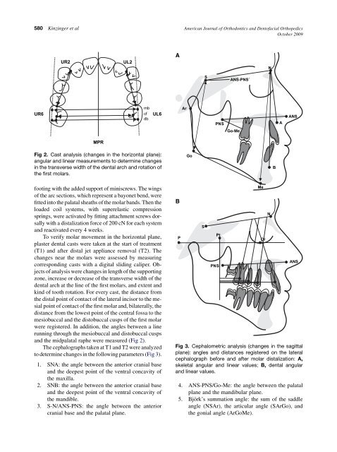
Fig 2. Cast analysis (changes in the horizontal plane):<br />
angular and linear measurements to determine changes<br />
in the transverse width of the dental arch and rotation of<br />
the first molars.<br />
Go<br />
B<br />
footing with the added support of miniscrews. The wings<br />
of the arc sections, which represent a bayonet bend, were<br />
fitted into the palatal sheaths of the molar bands. Then the<br />
loaded coil systems, with superelastic compression<br />
springs, were activated by fitting attachment screws dorsally<br />
with a distalization force of 200 cN for each system<br />
and reactivated every 4 weeks.<br />
To verify molar movement in the horizontal plane,<br />
plaster dental casts were taken at the start of treatment<br />
(T1) and after distal jet appliance removal (T2). The<br />
changes near the molars were assessed by measuring<br />
corresponding casts with a digital sliding caliper. Objects<br />
of analysis were changes in length of the supporting<br />
zone, increase or decrease of the transverse width of the<br />
dental arch at the line of the first molars, and extent and<br />
kind of tooth rotation. For every cast, the distance from<br />
the distal point of contact of the lateral incisor to the mesial<br />
point of contact of the first molar and, bilaterally, the<br />
distance from the lowest point of the central fossa to the<br />
mesiobuccal and the distobuccal cusps of the first molar<br />
were registered. In addition, the angles between a line<br />
running through the mesiobuccal and distobuccal cusps<br />
and the midpalatal raphe were measured (Fig 2).<br />
The cephalographs taken at T1 and T2 were analyzed<br />
to determine changes in the following parameters (Fig 3).<br />
1. SNA: the angle between the anterior cranial base<br />
and the deepest point of the ventral concavity of<br />
the maxilla.<br />
2. SNB: the angle between the anterior cranial base<br />
and the deepest point of the ventral concavity of<br />
the mandible.<br />
3. S-N/ANS-PNS: the angle between the anterior<br />
cranial base and the palatal plane.<br />
B<br />
P<br />
S<br />
Pt<br />
PNS<br />
4. ANS-PNS/Go-Me: the angle between the palatal<br />
plane and the mandibular plane.<br />
5. Björk’s summation angle: the sum of the saddle<br />
angle (NSAr), the articular angle (SArGo), and<br />
the gonial angle (ArGoMe).<br />
Me<br />
Or<br />
N<br />
ANS<br />
Fig 3. Cephalometric analysis (changes in the sagittal<br />
plane): angles and distances registered on the lateral<br />
cephalograph before and after molar distalization: A,<br />
skeletal angular and linear values; B, dental angular<br />
and linear values.