DATASHEET
Download Datasheet PDF - Cylon Controls
Download Datasheet PDF - Cylon Controls
- No tags were found...

Create successful ePaper yourself
Turn your PDF publications into a flip-book with our unique Google optimized e-Paper software.
<strong>DATASHEET</strong><br />
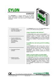
UCU Room Display<br />
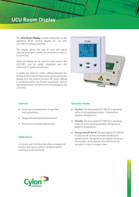
The UCU Room Display provides dedicated visually<br />
appealing Room Control display for use with<br />
UCU10FC/K Unitary Controller.<br />
The display allows the user to view and adjust<br />
selected parameters within the controller to which it<br />
is connected.<br />
While the display can be used for local control, the<br />
UCU10FC can be easily integrated into the<br />
UnitronUC32 system architecture.<br />
It avoids the need for mains cabling between the<br />
display and the Fancoil equipment, by separating the<br />
display from the control function. All mains cabling<br />
is contained within the Fancoil equipment, while a<br />
lightweight serial connection joins the Display to the<br />
controller.<br />
Features<br />
Local view and adjustment of specified<br />
room parameters<br />
Integrated space temperature sensor<br />
Mounts onto standard pattress box<br />
Applications<br />
A numeric user interface that allows occupants to<br />
monitor and adjust comfort conditions within<br />
individual rooms and zones<br />
Operation Modes<br />
Comfort: The associated UCU10FC/K is operating<br />
within its occupied parameters. Temperature<br />
setpoint, fanspeed etc.<br />
Standby: The associated UCU10FC/K is operating<br />
within its unoccupied parameters. Temperature<br />
setpoint, fanspeed etc.<br />
Energy Hold Off (EHO): The associated UCU10FC/K<br />
is switched off, so that all enable and demand<br />
signals are off. Temperature and digital inputs are<br />
monitored in order that the UCU10FC/K can be<br />
activated in case of an alarm state.
UCU Room Display<br />
21mm.<br />
87mm.<br />
4-digit display<br />
of current value, time,<br />
control parameter or<br />
setpoint<br />
Unit<br />
of displayed value,<br />
(°C or °F as set in<br />
controller strategy)<br />
Fan Speed<br />
graphical indication<br />
88mm.<br />
4-digit display<br />
of current value, time,<br />
control parameter or<br />
setpoint<br />
Operation modes:<br />
Comfort<br />
Standby mode<br />
Energy Hold Off<br />
Symbols:<br />
Heating Active<br />
Cooling Active<br />
Fan Active<br />
Manual Fan<br />
POWER button:<br />
Pressing the button less<br />
than 2 sec toggles standby<br />
and comfort mode.<br />
Pressing the button for<br />
more than 2 seconds<br />
switches the unit off.<br />
UP button<br />
increment<br />
temperature<br />
set point<br />
DOWN button<br />
decrement<br />
temperature<br />
set point<br />
OPTION button:<br />
Selects fan speed<br />
fan1, fan2, fan3 or<br />
AUTO<br />
Error messages<br />
Err1:<br />
Err2:<br />
Err3:<br />
Communication Error between Base and Terminal. Verify wiring. Make<br />
sure data line are not mixed up or interrupted.<br />
Faulty temperature sensor: The temperature sensor may be<br />
damaged or not present.<br />
General fan coil device error<br />
<br />
©2012 Cylon Controls. All Rights Reserved<br />
WWW.CYLON.COM<br />
UCDS0063.rev11<br />
Subject to change without notice
UCU Room Display<br />
Operation of the Room Display<br />
Switching ON<br />
The unit is switched on by pressing the POWER button while in EHO mode. It will start up in comfort mode.<br />
Changing between COMFORT and STANDBY<br />
Pressing the POWER button for less than 2 seconds toggles between STANDBY and COMFORT modes.<br />
Switching OFF<br />
Pressing the POWER button for more than 2 seconds, will switch the unit off. OFF and temperature will be displayed in the LCD.<br />
Standard loop display<br />
The large digits indicates the room temperature, the small digits display the set point and the vertical bar on the right side shows the active<br />
fan speed.<br />
Changing of setpoints<br />
Press UP/DOWN keys to change temperature setpoint. Changing of setpoints may be disabled and set point ranges can be limited.<br />
Manual override of fan speeds<br />
Manually change fan speeds by pressing the OPTION key for less than 3 seconds. Repeatedly pressing the OPTION key will toggle through<br />
these fan speed selections: Fan LOW > Fan MEDIUM > FAN HIGH > FAN ECO. Any other selection than FAN ECO will display the manual<br />
override sign.<br />
Specifications<br />
POWER SUPPLY<br />
Operating voltage<br />
Power consumption<br />
Electrical Connection<br />
TEMPERATURE INPUT<br />
Type<br />
Range<br />
Accuracy<br />
COMMUNICATION<br />
Communication type<br />
10…28 V DC<br />
Max 50mA<br />
4 way screw connector<br />
NTC 10kΩ @ 25°C (77°F)<br />
0…50 °C (32…122 °F)<br />
0.2 K<br />
RS485<br />
ENVIRONMENT<br />
Operation To IEC 721-3-3<br />
Climatic Conditions<br />
Temperature<br />
Humidity<br />
class 3 K5<br />
0…50 °C (32…122 °F)<br />
UCU Room Display<br />
Cx<br />
CMN<br />
Tx<br />
Rx<br />
12 V<br />
RS485 A+<br />
GND<br />
RS485 B -<br />
Fieldbus A+<br />
Fieldbus B -<br />
GENERAL<br />
OPA Dimensions (H x W x D) 88 x 88 x 21 mm (3.5” x 3.5” x 0.8”)<br />
Housing Material<br />
Fire proof ABS plastic<br />
Mounting Plate<br />
Zinc coated steel<br />
Standard Colour White RAL 9003<br />
Weight (including package) 80 g (2.8 oz)<br />
Installation<br />
1. Install the mounting plate straight to the wall or the flush mounting box. Make sure that the nipple with the front holding screw<br />
is facing to the ground. Make sure the screw heads do not stand out more than 5 mm of the surface of the mounting plate.<br />
2. Plug in the communication cable fitted with a male RJ11 connector to the RJ11 connector located on the backside of the<br />
terminal.<br />
3. Slide the two latches located on the top of the front part into the hooks of the mounting plate.<br />
4. Lower the front part until located flat on the wall and the mounting plate is not visible anymore. Make sure the connection<br />
cable does not get into the way.<br />
5. Tighten the front holding screw to secure the front part to the mounting plate.<br />
Cabling<br />
Note: the UCU Room Keypad must be used in conjunction with either UCU10FC/K or CBT12K Field Controller<br />
Room<br />
Display<br />
1<br />
2<br />
3<br />
4<br />
12 V<br />
GND<br />
RS485 A+<br />
RS485 B -<br />
3 Universal Inputs I<br />
RS485<br />
Fieldbus<br />
Port<br />
Service Port<br />
pin no:<br />
1<br />
2<br />
3<br />
4<br />
5<br />
6<br />
7<br />
8<br />
37 38 39 40<br />
35 36<br />
UCU10FC/K<br />
CBT12K<br />
pin no:<br />
17 18 19 20 21 22 23 24 25 26 27 28 29<br />
Outputs<br />
32 33 34<br />
©2012 Cylon Controls. All Rights Reserved<br />
WWW.CYLON.COM<br />
UCDS0063.rev11<br />
Subject to change without notice
UCU Room Display<br />
Field Controller Strategy point setup<br />
Type Number Use Values<br />
Analog 255 Temperature Setpoint 15-30 Deg C, 59-86 Deg F<br />
Analog 254 Upper Setpoint Limit 15-30 Deg C, 59-86 Deg F<br />
Analog 253 Lower Setpoint Limit 15-30 Deg C, 59-86 Deg F<br />
Analog 252 Fan Speed 0 = off, 1 = low, 2 = medium, 3 = high<br />
Analog 251 Room Temperature in -40.0 – 959.9 Deg C/Deg F<br />
Analog 250 Control Flags (See description below)<br />
Analog 249 Power Mode 0 = off, 1 = standby, 2 = comfort<br />
Analog 248 Room Temperature out -40.0 – 959.9 Deg C/Deg F<br />
Digital 255 Operational Mode 0 = heating, 1 = cooling<br />
Digital 254 Keypad Link Status 0 = offline, 1 = online<br />
Digital 252 Manual Fan Control 0 = automatic, 1 = manual<br />
Digital 251 Fan Type 0 = three speed fan, 1 = single speed fan<br />
Control Flags (analog point 250) : Analog point 250 is used to specify all of the Control Flags. This is set in the Controller and<br />
sent from the Controller to the display. A value between 0 and 127 is used to represent the following bit pattern for Flag values:<br />
bit 0 :: Manual fan disable flag : When this flag is set, the keypad will allow the user adjust the setpoint value but not the fan<br />
speed. If the user tries to change fan speed when this flag is set, the word “no” is displayed in order to give a feedback<br />
(assuming fan display inhibit flag is NOT set).<br />
bit 1 :: Fan display inhibit : When this flag is set and the manual fan disable flag is set, the keypad does not display any fan<br />
status information. This allows for operation in VAV type applications where there is no requirement for user fan<br />
adjustment or status. If the manual fan disable flag is clear this flag is ignored.<br />
bit 2 :: Power control flag : When this flag is set the user is not allowed to change the current power mode (i.e. comfort,<br />
standby, off). This is for out of occupancy lockdown.<br />
bit 3 :: Local echo flag : When this flag is set the keypad will update the local display based on the users input without waiting<br />
for the update acknowledge from the UCU. This may improve the apparent user responsiveness of the display but<br />
could lead to some glitches if the UCU needs to vet user responses and override them.<br />
bit 4 :: Fahrenheit/Celsius flag : This is set by the UCU and used by the display to decide which temperature units to use.<br />
bit 5 :: Error lockout flag : When this flag is set, all keypad functionality is disabled, and the “Err3” code is displayed to indicate<br />
a fancoil error state.<br />
bit 6 :: room temperature override flag : When this flag is set, the keypad will display the temperature value supplied by the<br />
Controller instead of the value from the keypad’s internal temperature sensor. This would allow the use of external<br />
temperature sensors attached to the Controller or would allow the Controller adjust the temperature from the keypad<br />
sensor to compensate for errors<br />
©2012 Cylon Controls. All Rights Reserved<br />
WWW.CYLON.COM<br />
UCDS0063.rev11<br />
Subject to change without notice