

AMATEUR RADIO
Fig. - Free and Open Source Software
Fig. - Free and Open Source Software
- No tags were found...

Create successful ePaper yourself
Turn your PDF publications into a flip-book with our unique Google optimized e-Paper software.
Build A<br />
kW Linear<br />
- - a 4-1000 provides<br />
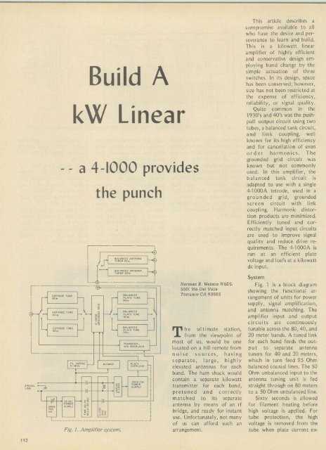
Fig. t, Amplifier system.<br />
the punch<br />
G"<br />
eA'4""£O<br />
I ;.fI:<br />
f<br />
UTE"".<br />
U" ' ••0 ..<br />
a_lucl O 'NTE"".<br />
l fU"E" ~o ~ H<br />
.. --<br />
..<br />
,<br />
.- . - ..<br />
CATHOoE TU"<br />
""""CEO<br />
Pe AT,<br />
I r '0- "'N' -<br />
f-<br />
... .'<br />
PcUE<br />
0,0<br />
r_ CAT~O D ' Tu'" f- '~ 0 eAL,"C"<br />
.,<br />
--' -<br />
TUN'<br />
•<br />
•,L_<br />
...<br />
L. CA'''OC[ TU "<br />
BACO NCED<br />
f- L. PL ATE Tv",<br />
TRANS',"_<br />
VO "oT,A l OC_<br />
.. OyAC<br />
CO '<br />
""'<br />
~ .<br />
... !'<br />
...<br />
f-<br />
-. .- _.. - .. .. - 1- ..-<br />
I rI, . ARI " ~ 8 LOi/rU<br />
I<br />
P lA"<br />
0-'00_ O_'R'OAQ<br />
-<br />
r-r-<br />
, II -.<br />
-,<br />
UVCC<br />
pO" • •<br />
'.<br />
~ . SUO""<br />
I<br />
-<br />
-<br />
I<br />
I<br />
I<br />
I<br />
I<br />
I<br />
,"OOVl>O<br />
o.<br />
. 0<br />
POwER<br />
".<br />
SU"Pc><br />
"<br />
> 0 I<br />
I<br />
.-<br />
,<br />
I<br />
I<br />
" ;<br />
•..<br />
I<br />
"'~<br />
••<br />
I<br />
0<br />
'--<br />
- .'<br />
I<br />
~<br />
00<br />
•• ••<br />
L____ __ ~_________________ _ _ __ _ _ _ _.J<br />
T<br />
h<br />
Nor man B. Watson W6DL<br />
5501 Via Del VaIle<br />
Torrance CA 90505<br />
e ultimate station,<br />
from the viewpoint of<br />
most of us, woul d be o ne<br />
located on a hill remote from<br />
n o i s e sources, havi ng<br />
separate, large, highly<br />
elevated antennas for each<br />
band. The ham shack would<br />
contain a separate kilowatt<br />
transmitter for each band,<br />
pre tu ned and cor rectly<br />
matc hed to its separate<br />
antenna by means of an rf<br />
bridge, and ready for instant<br />
use. Unfortunately, not many<br />
of us can afford such an<br />
arrangement.<br />
This article describes a<br />
compromise available to all<br />
who have the desire and perseverance<br />
to learn and build.<br />
Th is is a kilowatt linear<br />
amplifier of highly efficient<br />
and conservative design employing<br />
band change by the<br />
simple actuation of three<br />
switches. In its design, space<br />
has been conserved; however,<br />
size has not been restricted at<br />
the expense of efficiency,<br />
reliabil ity, or signal quali ty.<br />
Quite common in the<br />
1930's and 40's was the pushpull<br />
out put circuit using two<br />
tubes, a bala nced tank circuit,<br />
a n d link coupling, we ll<br />
known for its high efficiency<br />
and for cancellation of even<br />
o rder harmonics. T h e<br />
grounded grid circuit was<br />
known but not commonly<br />
used. In this amplifier, the<br />
b ala nced tank circuit is<br />
adapted to use with a single<br />
4-1000A tetrode, used in a<br />
grounded gri d, grounded<br />
screen circuit with link<br />
coupli ng. Harmo nic distortion<br />
prod ucts are minimized.<br />
Efficiently tuned an d correctly<br />
matched input circuits<br />
are used to improve signal<br />
quality and reduce drive requirements.<br />
The 4-1000A is<br />
run at an efficient plate<br />
voltage and loafs at a kilowatt<br />
de input.<br />
System<br />
Fig. 1 is a block diagram<br />
showing the functional arrangement<br />
of units for power<br />
sup ply, signal amplification,<br />
and antenna matching. The<br />
amplifier input and output<br />
circuits are continuously<br />
tunable across the 80, 40, an d<br />
20 meter bands. A tuned link<br />
for each band feeds the output<br />
to separate an tenna<br />
tuners for 40 and 20 meters,<br />
which in turn feed 95 Ohm<br />
balanced coaxial lines. The 50<br />
Ohm unbalanced input to the<br />
antenna tuning unit is fed<br />
straight thro ugh on 80 meters<br />
to a 50 Ohm unbalanced line.<br />
Sixty seconds is allowed<br />
for filament heat ing before<br />
high voltage is applied. For<br />
tu be protectio n, the high<br />
voltage is removed from the<br />
tube when plate current ex-<br />
112


