Understanding Process Vacuum for Process Improvement
Understanding Process Vacuum for Process ... - Everest Blowers
Understanding Process Vacuum for Process ... - Everest Blowers
- No tags were found...

You also want an ePaper? Increase the reach of your titles
YUMPU automatically turns print PDFs into web optimized ePapers that Google loves.
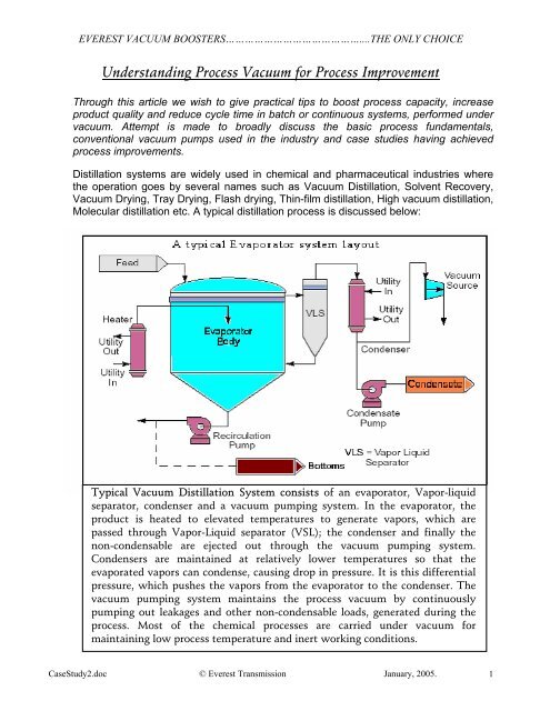
EVEREST VACUUM BOOSTERS……………………………………....THE ONLY CHOICE<br />
“How can process capacity be increased?” The answer to this can easily be worked<br />
out by analyzing the following: -<br />
• By how much do we need / can increase the output?<br />
• What is system design capacity?<br />
• Are current process yields optimized?<br />
• Additional constraints needed to be impose (i.e., capital, time or regulatory)?<br />
• Where is the bottleneck?<br />
The answers to these basic questions can dramatically improve the process efficiency.<br />
In most of the processes the basic answer to the above would be to “Improve the<br />
<strong>Vacuum</strong> pumping system capabilities”. We discuss under, basic terminology used<br />
frequently in reference to the vacuum process.<br />
What is <strong>Vacuum</strong>?<br />
<strong>Vacuum</strong> is simply a pressure below atmosphere. To create vacuum in a system, a<br />
pump is required to remove mass (gas/vapor) from the system. The more mass is<br />
removed; lower is the pressure that exists inside the system. Various vacuum levels are<br />
defined depending upon the ultimate absolute pressure, in Torr (mmHg),<br />
Coarse <strong>Vacuum</strong><br />
Medium <strong>Vacuum</strong><br />
Fine <strong>Vacuum</strong><br />
Ultra High <strong>Vacuum</strong><br />
10 – 760 Torr<br />
0.001 – 10 Torr<br />
10 - 3 – 10 - 7 Torr<br />
EVEREST VACUUM BOOSTERS……………………………………....THE ONLY CHOICE<br />
Ultimate vacuum/Blank-Off vacuum: - The limiting pressure approached in the<br />
vacuum system after sufficient pumping time to establish that further reductions in<br />
pressure will be negligible. It is the final pressure achieved by a pump under blank-off<br />
condition when the throughput is practically zero. At this stage the pump does not pump<br />
any air/vapor and no further drop in pressure is possible.<br />
For most of the chemical processes vacuum-pumping system is designed to take care<br />
of process load and maintain the process to the desired levels of pressures. <strong>Process</strong><br />
loads mainly consist of:<br />
• Plant air leakage load.<br />
• <strong>Process</strong> non-condensable such as dissolved gases.<br />
• <strong>Process</strong> condensable load - vapors which escape the condenser<br />
The sum of the individual loads must be effectively pumped out to maintain the process<br />
vacuum. For example a load of 10Kg of Air Leakage at 100 Torr (660mmhg) vacuum,<br />
20ºC needs a pump of pumping capacity 63 m 3 /hr and <strong>for</strong> the same load at 10 Torr the<br />
Pumping speed required would be 630 m 3 /hr and at 1 Torr would need a pumping speed<br />
of 6300 m 3 /hr.<br />
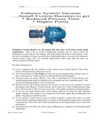
Mechanical <strong>Vacuum</strong> Boosters,<br />
manufactured by EVEREST, are<br />
being extensively used in chemical<br />
process industry to boost the<br />
per<strong>for</strong>mance of the vacuum pumps,<br />
especially in low-pressure range,<br />
where conventional vacuum pumps<br />
have poor volumetric efficiency.<br />
Everest Boosters are capable of<br />
moving large quantity of gas at low<br />
pressures, with far smaller power<br />
consumption than <strong>for</strong> any other<br />
equipment now available.<br />
The internals of a Booster are totally free of any sealant fluid, and there<strong>for</strong>e the pumping is<br />
dry. Due to the vapor Compression by the booster, the pressure at the discharge of the<br />
booster is relatively high, resulting in higher volumetric of the backing pump. Everest Twin<br />
Lobe Boosters are used in series with a variety of backing pumps to achieve higher<br />
speeds and lower ultimate pressures.<br />
CaseStudy2.doc © Everest Transmission January, 2005. 3
EVEREST VACUUM BOOSTERS……………………………………....THE ONLY CHOICE<br />
The Table below gives a rough estimate of how the boosters enhance the working<br />
vacuums of the process when installed in combination with various types of vacuum<br />
pumps. Various types of backing pump can be used, depending upon the system<br />
requirement and ultimate vacuum needs. However, the final vacuum is governed by the<br />
suitable selection of the backing pump and booster combination. The table below gives a<br />
broad range of vacuum achieved with various backing pumps combinations.<br />
<strong>Vacuum</strong> Pump<br />
Absolute Pressure Range<br />
Pressure achievable with<br />
Booster<br />
Single Stage Ejector 150 Torr 15 – 30 Torr<br />
Water Ejector 100 Torr 10 – 20 Torr<br />
Water Ring Pump 40 – 60 Torr 5 – 10 Torr<br />
Liquid Ring Pump 20 – 30 Torr 2 – 5 Torr<br />
Piston Pumps 20 – 30 Torr 2 – 5 Torr<br />
Rotary Piston Pumps 0.1 Torr 0.01 Torr<br />
Rotary Vane Oil Pump 0.01 – 0.001 Torr 0.001 – 0.0001 Torr.<br />
Water Ring Pump :- is the most widely used vacuum pump in the chemical process industry<br />
and there<strong>for</strong>e, is broadly discussed <strong>for</strong> understanding and improvement.<br />
OPERATING PRINCIPLE OF A WATER RING PUMP<br />
In a cylindrical housing, partially filled with sealing liquid, a multi-blade impeller on a shaft<br />
is positioned eccentrically. Port plates with inlet and discharge openings are positioned on<br />
either side of the impeller. A liquid ring is created by the centrifugal <strong>for</strong>ce generated by<br />
the rotating impeller. The centrifugal <strong>for</strong>ce holds the liquid ring against the inner wall of<br />
the pumping chamber. Since the impeller is located eccentric to the pumping chamber,<br />
the depth of entry of the blades into the liquid ring decreases and increases as the<br />
impeller rotates. This creates increasing impeller cell volume on the inlet port side,<br />
creating a vacuum. On the discharge port side, the impeller cell volume decreases, as the<br />
blades move further into the liquid ring, increasing the pressures, until discharge takes<br />
place through the discharge port. A continuous flow of fresh sealing liquid is supplied to<br />
the pump via the sealing liquid inlet.<br />
CaseStudy2.doc © Everest Transmission January, 2005. 4
EVEREST VACUUM BOOSTERS……………………………………....THE ONLY CHOICE<br />
The figure above shows typical pumping speeds of Water ring pump and Ejector, which<br />
are very popular in the chemical process industry. These pumps have water as the<br />
sealing/motive fluid and there<strong>for</strong>e, cannot work beyond the saturated vapor pressure of<br />
water, to corresponding temperature. As evident from the curve above, the effective<br />
pumping speed drops drastically at low-pressure range and the overall process becomes<br />
inefficient, un-economical and slow. Liquid Ring Pumps are used throughout process<br />
industry. Un<strong>for</strong>tunately they suffer from few limitations, such as<br />
• The final vacuum achievable is largely dependent on the vapor<br />
pressure of the pump fluid corresponding to the working<br />
temperatures. For water sealed pumps, the lowest practical operating<br />
pressure <strong>for</strong> two-stage design would be 60 Torr (700mm Hg) <strong>for</strong> exit<br />
water temperature at 30-32 ºC.<br />
• Their energy consumption per unit of gas pumped is higher since<br />
most of it is lost in handling pump fluid.<br />
• It requires large quantities of sealing fluid.<br />
• It adds load on the ETP system.<br />
Economical solution to overcome the above limitations is installation of mechanical<br />
vacuum Booster to boost the vacuum pumping system per<strong>for</strong>mance. Case studies<br />
discussed establish that drastic process improvements have been achieved on installation<br />
of Mechanical Booster only. Mechanical vacuum boosters cover a vast capacity &<br />
pressure range making them an ideal choice <strong>for</strong> process engineers <strong>for</strong> practically all<br />
process applications.<br />
CaseStudy2.doc © Everest Transmission January, 2005. 5
EVEREST VACUUM BOOSTERS……………………………………....THE ONLY CHOICE<br />
Invariably the process demands<br />
higher working vacuums and the<br />
process engineers’ end up<br />
selecting higher capacity pumps<br />
adding to considerable capital &<br />
working costs with little or no<br />
gain in vacuum. For example if a<br />
process demands system<br />
pressures to be maintained at 50<br />
Torr (710mmHg) with non<br />
condensable load of 10 Kg/hr at<br />
30ºC, ideal pump should have a<br />
capacity of 130m 3 /hr at 50 Torr.<br />
Use of water ring pump which<br />
has it’s ultimate at 710mmHg<br />
would be a wrong choice. A<br />
Booster and Water ring<br />
combination would be the<br />
most energy efficient choice.<br />
BOOSTER DISTILLATION UNIT<br />
EVEREST MECHANICAL VACUUM BOOSTER<br />
CaseStudy2.doc © Everest Transmission January, 2005. 6
EVEREST VACUUM BOOSTERS……………………………………....THE ONLY CHOICE<br />
Case Study 1<br />
A Vanaspathi oil De-odorizing plant in Bikaner, Rajasthan was carrying out the process of deodourisation<br />
of oil in a batch process of 10MT batch. The oil was heated to about 270ºC in the<br />
evaporator and the vapors generated were passed through Barometric leg direct water<br />
condenser followed by Water-ring pump of 7.5HP. The process was maintained under<br />
vacuum of the range 680-700 mmHg, the best a good water ring pump could achieve. During<br />
the process about 100Kg/hr of stripping steam was injected into the oil. The entire process<br />
had about 10-12 hours of cycle time. The process engineers wanted better process<br />
vacuum <strong>for</strong> better product quality. The conventional option of installation of multi stage<br />
Steam-jet ejectors was ruled out due to unavailability of additional high-pressure steam.<br />
The technical team of Everest studied the process and available utilities and suggested<br />
installation of Mechanical <strong>Vacuum</strong> Booster. To increase the process vacuum the vacuum<br />
pumping system capabilities had to be improved so that lower pressures could be achieved at<br />
the evaporator. There was no need to reduce the pressures at the condenser, as higher<br />
pressure in the condenser would increase the condenser efficiency. A mechanical vacuum<br />
Booster combination was proposed <strong>for</strong> installation between the evaporator and the condenser<br />
so as to create low pressure at the evaporator.<br />
The mechanical <strong>Vacuum</strong> Booster combination was installed, as illustrated in the figure. The<br />
installation was easily and quickly completed, as it required little modification in piping only<br />
and was done without disturbing any of the process vessels.<br />
System was put in operation and following results were observed:<br />
• Required vacuum levels in the range of 755-758 mmHg (3-5 Torr) were<br />
achieved and the desired product quality was easily achieved.<br />
• Due to the vapor compression at the discharge, condenser efficiency<br />
increased allowing less stringent control on inlet water temperature.<br />
• Requirement of stripping stream was reduced to almost half. The<br />
specific volume of steam at 60 Torr is about 23m 3 /kg and at 3 Torr is<br />
about 407m 3 /Kg, almost 17 times higher. The reduced quantity of<br />
stripping steam was net direct saving apart from the indirect benefit of<br />
reduced load on the condenser and the cooling towers.<br />
• A Pre-condenser installed in between the Evaporator and the Booster, to<br />
cool the incoming hot vapors, acted as a trap and a fairly good amount<br />
of evaporated FFA vapors condensed in there. This condensed FFA was<br />
drained after every batch. The contamination of the water in the<br />
condenser was there<strong>for</strong>e, minimized reducing load on the ETP system.<br />
• The process cycle time was reduced by 2 hours.<br />
CaseStudy2.doc © Everest Transmission January, 2005. 7
EVEREST VACUUM BOOSTERS……………………………………....THE ONLY CHOICE<br />
Technical comments: The vapors from the evaporator travel towards the condenser due to<br />
the differential pressures that exist between the two, created by the temperature difference.<br />
The rate of flow of vapors from the evaporator to condenser would, there<strong>for</strong>e, depend on the<br />
differential pressure and the line conductance connecting the two. In this configuration the<br />
mechanical <strong>Vacuum</strong> Booster pumps out the vapors generated in the evaporator and <strong>for</strong>ce<br />
them towards the condenser. Due to the mechanical pumping action by the Boosters low<br />
pressures are generated in the evaporator, accelerating the vapor generation whereas higher<br />
pressures are created in the condenser, accelerating vapor condensation.<br />
EVEREST MECHANICAL VACUUM BOOSTER<br />
CaseStudy2.doc © Everest Transmission January, 2005. 8
EVEREST VACUUM BOOSTERS……………………………………....THE ONLY CHOICE<br />
Case Study2<br />
A Pesticide manufacturing company in Lote Parshuram, Maharashtra had a process<br />
involving solvent recovery of Ethylene dichloride (EDC). The process was being done under<br />
vacuum and the vacuum pump used was conventional water ring type of 330m 3 /hr. The<br />
process pressure levels were in the range of 80-90 Torr and the batch cycle time, to attain<br />
product purity of 95%, was 8-9 hours. The process engineers wanted better product purity <strong>for</strong><br />
which the team of Everest studied the process and recommended improvement in vacuum<br />
levels by installation of 800 m 3 /hr vacuum booster.<br />
As per the Raoults law, ”In a solution, vapour pressure of a component (at a given<br />
temperature) is equal to the whole fraction of that component in the solution<br />
multiplied by the vapour pressure of that component in the pure state”.<br />
Based on the above law, recommendations were made <strong>for</strong> better vacuum and it was<br />
anticipated that with the increase in vacuum, process would be able to achieve higher<br />
product purity with reduction in time. <strong>Vacuum</strong> booster was installed with a mechanical bypass<br />
line across it, as shown in the figure (Case 2 Fig 2). The same water ring pump was<br />
used as a backing pump to maintain a backing pressure, at the discharge of the booster, to<br />
around 80 Torr. The process operation was modified slightly in which initially the booster was<br />
by-passed and solvent recovery done directly by Water Ring Pump, as the initial solvent<br />
recovery was at a much higher rate. Subsequently, as the concentration of the solvent got<br />
reduced, demand <strong>for</strong> better vacuum was essential and at that stage, the by-pass valve was<br />
closed and booster switched on. With booster in operation, the process pressure dropped to<br />
20-25 Torr from 80-90 Torr, thereby, accelerating solvent recovery. The product of purity 97-<br />
98% was achieved with reduction in batch cycle time by three hours. This amounted not only<br />
in better product purity but also increase in the production by about 30%.<br />
CaseStudy2.doc © Everest Transmission January, 2005. 9
EVEREST VACUUM BOOSTERS……………………………………....THE ONLY CHOICE<br />
Technical Comments:<br />
EVEREST MECHANICAL VACUUM BOOSTER<br />
WITH A MECHANICAL BYPASS VALVE<br />
In the process of solvent recovery / drying, as per Raoults law, the initial rate of evaporation<br />
of solvent, when the percentage of solvent is more, is high. Gradually, the rate of evaporation<br />
drops and can only be increased either by increase in temperature or reduction in pressure.<br />
At this stage, booster is put into operation reducing the system pressure which in turn<br />
accelerates the rate of evaporation resulting in more evaporation of solvent and reduction in<br />
process time.<br />
CaseStudy2.doc © Everest Transmission January, 2005. 10
EVEREST VACUUM BOOSTERS……………………………………....THE ONLY CHOICE<br />
Case Study 3<br />
An energy drink powder manufacturing company at Nabha, Punjab had a process of multipass<br />
evaporation <strong>for</strong> drying of viscous solution of energy drink powder. The drying of the<br />
solution was done up to final concentration of 82%, in multi-pass evaporator, which was then<br />
transferred to vacuum tray dryers <strong>for</strong> total drying. The multi-pass evaporation (MPV) had<br />
multiple evaporators followed by direct (Barometric leg) condenser and 7.5HP Water Ring<br />
Pump. The cooling water in the direct condenser was of 30ºC and the condenser pressure<br />
was maintained at about 100 Torr. The total batch cycle time was 2 hours 30 minutes.<br />
The client wanted reduction in batch cycle time with increase in concentration up to 85%.<br />
Everest technical team studied the installation and suggested installation of 3HP Mechanical<br />
<strong>Vacuum</strong> Booster between the multi-pass evaporator and the condenser (refer figure). On<br />
installation, client was able to achieve the following improvements:<br />
• Reduction in batch cycle time by 20%.<br />
• Increase in <strong>Vacuum</strong> from 100-120 Torr to 40-45 Torr.<br />
• Increase of concentration to 84% in the reduced time.<br />
• Dependence on cooling water temperature was minimized since the<br />
saturated vapour pressure of water in the condenser, after<br />
installation of booster was of little importance.<br />
CaseStudy2.doc © Everest Transmission January, 2005. 11
EVEREST VACUUM BOOSTERS……………………………………....THE ONLY CHOICE<br />
Technical Comments:<br />
In a direct condenser, the saturated vapour pressure of the cooling water determines the<br />
condenser pressure. In the last pass of evaporator, the vapour temperature is close to 50-<br />
55ºC at which the saturated vapour pressure is about 56-60 Torr. The differential pressure<br />
between the evaporator and the condenser is the net driving <strong>for</strong>ce, driving vapours from<br />
evaporator to condenser. Mechanical <strong>Vacuum</strong> Booster installed accelerates the transfer of<br />
vapours resulting in higher through-put, higher purity & reduced process time.<br />
Article compiled by Technical Team of Everest Transmission. For further clarifications please<br />
contact:<br />
EVEREST TRANSMISSION<br />
B-44, Mayapuri Industrial Area, Phase-1, New Delhi-110064, India.<br />
Telefax: 91-11-28114944, 28114955, 28117469, 28116307<br />
Email: info@everestblowers.com Web: www.everestblowers.com<br />
CaseStudy2.doc © Everest Transmission January, 2005. 12