I-B SERIES - John Crane
I-B SERIES - John Crane
I-B SERIES - John Crane

You also want an ePaper? Increase the reach of your titles
YUMPU automatically turns print PDFs into web optimized ePapers that Google loves.
Powerstream B Series Couplings<br />
Fitting, & Maintenance Instructions.<br />
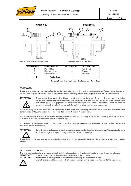
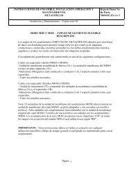
FIGURE 1a FIGURE 1b<br />
1 4<br />
M<br />
M<br />
DBSE<br />
Non-Spacer Sizes B068 to B180 Spacer Sizes B080 to B180<br />
REFERENCE DESCRIPTION REFERENCE DESCRIPTION<br />
1 Part 1 Hub 5 Part 5 Hub<br />
2 Rubber Insert 6 Spacer<br />
3 Spacer Bolt 7 Jaw Body<br />
4 Part 4 Hub<br />
Powerstream is a registered trademark of <strong>John</strong> <strong>Crane</strong><br />
Part No<br />
I-B <strong>SERIES</strong><br />
Page 1 of 4<br />
FOREWORD<br />
These instructions are provided to familiarise the user with the coupling and its designated use. These instructions must<br />
be read and applied whenever work is carried out on the coupling and must be kept available for future reference.<br />
ATTENTION These instructions are for the fitting, operation and maintenance of the coupling as used in rotating<br />
equipment and will help to avoid danger and increase reliability. The information required may change<br />
with other types of equipment or installation arrangements. These instructions must be read in<br />
conjunction with the instruction manuals for both the driver and driven machinery.<br />
!<br />
If the coupling is to be used for an application other than that originally intended or outside the recommended<br />
performance limits, <strong>John</strong> <strong>Crane</strong> must be contacted before its installation and use.<br />
Improper handling, installation, or use of this coupling may affect any warranty. Contact the company for information as<br />
to exclusive product warranty and limitations of liability.<br />
If questions or problems arise, contact your local <strong>John</strong> <strong>Crane</strong> sales/service engineer or the original equipment<br />
manufacturer as appropriate.<br />
ATTENTION <strong>John</strong> <strong>Crane</strong> couplings are precision products and must be handled appropriately. Take particular care<br />
to avoid damage to spigots, mating faces, hub bores, & keyways.<br />
!<br />
2<br />
1<br />
7<br />
3 6<br />
5<br />
These instructions are written for standard catalogue products, generally designed in accordance with the drawing<br />
shown.<br />
SAFETY INSTRUCTIONS<br />
The following designations are used in the installation instructions to highlight instructions of particular importance.<br />
IMPORTANT is used for items of particular concern when using the coupling.<br />
ATTENTION where there is an obligation or prohibition concerning the avoidance of risk.<br />
where there is an obligation or prohibition concerning harm to people or damage to the equipment.<br />
!
Powerstream B Series Couplings<br />
Fitting, & Maintenance Instructions.<br />
Part No<br />
I-B <strong>SERIES</strong><br />
Page 2 of 4<br />
Storage<br />
If the coupling is not to be used immediately, it should be stored away from direct heat in its original packing.<br />
All documentation supplied with the coupling should be retained for future reference.<br />
Spares<br />
When requesting spares always quote the full designation of the coupling<br />
PREPARATION<br />
Remove coupling from packaging and carefully inspect for signs of damage. Remove protective coating/lubricant from<br />
bores & keyways. Remove all the bolts & nuts and dismantle the assembly.<br />
Hubs<br />
Powerstream couplings are supplied either pilot bored, or finished bore and keyed.<br />
Boring of Hubs<br />
If finish bore and key is required, it should be bored to required finish size by using the outside diameter (OD) of<br />
coupling and the hub face as a reference i.e. turn bore concentrically with respect to coupling OD & not the pilot bore<br />
diameter. (Refer figure 2) Locate the key-way midway between two holes/lugs in the hub. A tapped hole is required in<br />
the hub above the key-way, generally midway along the hub length.<br />
INSTALLATION OF COUPLING<br />
Installation of hubs<br />
!<br />
Ensure the hub bore and mating shaft are clean<br />
FIGURE 2<br />
0.1 mm<br />
Prior to installing the coupling, ensure that the machinery is made safe. Hubs must be<br />
adequately supported during installation to avoid accidental damage should they slip.<br />
Parallel Bored Hubs<br />
Check the hub bore and shaft diameters to verify that the desired fit will be achieved. Install the key into the shaft keyway<br />
and with a little lubrication on the shaft, slide the hub onto the shaft. The key should be a tight sliding fit in the keyway.<br />
Secure the hub to the shaft in the correct axial position with the grub screw.<br />
For normal applications the shaft ends should be flush with inner face of the hub. They can protrude beyond the<br />
clamping ring of the hub or remain inside if required, but sufficient gap should be allowed to take care of end float of<br />
both shafts (i.e. axial misalignment). Refer figure 1a & 1b. Ensure that the effective length of key is sufficient for<br />
transmission of rated torque of coupling.
Powerstream B Series Couplings<br />
Fitting, & Maintenance Instructions.<br />
Part No<br />
I-B <strong>SERIES</strong><br />
Page 3 of 4<br />
COUPLING ASSEMBLY<br />
Adjust the positions of the hubs on the shafts to maintain gap `M' as shown in figure 1a & 1b, and given in the<br />
table.<br />
Tighten the setscrew over the keys. Ensure the rubber elements are fitted in slots provided in Part No. 1 (Hub).<br />
For spacer type of couplings, the spacer assembly length is normally equal to the distance between shaft ends<br />
(DBSE). Refer figure 1b.<br />
Non spacer Design<br />
If the hub faces are flush with the shaft ends then for non-spacer couplings the distance between shaft ends (DBSE) is<br />
equal to gap M. (see figure 1a). Engage the lugs in hub (part 4) into the inserts located in the hub (part 1).<br />
Check the gap ‘M’, and if the shaft alignment is set then the coupling is ready for use.<br />
Spacer Design<br />
Set the DBSE to the required gap. Ensure rubber inserts are in the slots provided in hub (part 1)<br />
Locate jaw body (part 7) into the hub (part 1) as shown in figure 1b. Insert the spacer in between the Jaw body & hub<br />
(part 5).<br />
Tighten all bolts (part 3) as shown in figure 1b, to the tightening torque shown in the table.<br />
After completing assembly check gap ‘M’ is correct as given in table, and if the shaft alignment is set then the coupling<br />
is ready for use.<br />
Shaft Alignment<br />
Good shaft alignment is critical for the prolonged life of these couplings. The table gives the maximum permissible<br />
misalignments at initial assembly. <strong>John</strong> <strong>Crane</strong> alignment procedures should be followed to achieve these limits. Refer<br />
to <strong>John</strong> <strong>Crane</strong> data sheet I-ALIGN<br />
Initial Settings<br />
Coupling Size 068 080 095 110 125 140 160 180<br />
Spacer Bolt Tightening<br />
torque (N-m)<br />
N/A 13 13 31 31 62 62 62<br />
Flexible Gap M (mm) 2 to<br />
4<br />
2 to 4 2 to 4 2 to 4 2 to 4 2 to 4 2 to 6 2 to 6<br />
Parallel / Radial ∆Kr<br />
(mm)<br />
±0.1 ±0.1 ±0.1 ±0.1 ±0.1 ±0.1 ±0.1 ±0.1<br />
Axial ∆Ka (mm) ±0.4 ±0.4 ±0.4 ±0.4 ±0.4 ±0.4 ±0.4 ±0.4<br />
Angular ∆Kw (degree) 0.25° 0.25° 0.25° 0.25° 0.25° 0.25° 0.25° 0.25°<br />
OPERATION, INSPECTION AND MAINTENANCE<br />
Before starting the machinery, ensure that all necessary safety procedures are being observed<br />
and coupling guards are fitted<br />
!<br />
Routine examination should include a periodic check on the tightness of fasteners and visual<br />
inspection of transmission components for signs of fatigue or wear.<br />
If the coupled machinery is disturbed at any time, shaft alignment should be re-checked. Alignment checking is<br />
recommended if a deterioration of installation alignment during service is suspected.<br />
Maintenance work must only be carried out by suitably qualified personnel when the equipment is<br />
stationary and has been made safe.<br />
!<br />
Failures are rare and can generally be attributed to excessive misalignment or / and severe<br />
torsional overload. In all cases of coupling failure, the cause should be identified and corrected<br />
before replacing the coupling.<br />
ATTENTION When repairing <strong>John</strong> <strong>Crane</strong> Powerstream flexible couplings, only <strong>John</strong> <strong>Crane</strong><br />
approved parts should be used.
Powerstream B Series Couplings<br />
Fitting, & Maintenance Instructions.<br />
Part No<br />
I-B <strong>SERIES</strong><br />
Page 4 of 4


![B Series-Port [2675] - John Crane](https://img.yumpu.com/12598399/1/190x253/b-series-port-2675-john-crane.jpg?quality=85)