anywhere
Audio Enginnering magazine December 1953 - Vintage Vacuum ...
Audio Enginnering magazine December 1953 - Vintage Vacuum ...
- No tags were found...

Create successful ePaper yourself
Turn your PDF publications into a flip-book with our unique Google optimized e-Paper software.
O~~~-----------------------<br />
(A)<br />
::i<br />
"'<br />
~<br />
O ~1-T-IM-E----~~.~--------~~··~.~'~<br />
INTERVALS ,OF NO CURRENT FLOW<br />
(s)<br />
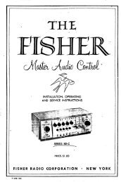
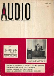
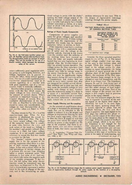
Fig. 15-3. (A) Full-wave rectifier output curre<br />
nt. (B) Rectifier current with insufficient load.<br />
The discontinuities create an increase in output<br />
voltage. This can be avoided by the use of a<br />
bleeder resistor, which increases the minimum<br />
value of the current.<br />
secure sufficiently good regulation without<br />
going to such lengths, however, and<br />
voltage regulators are in general reserved<br />
for other, more critical applications.<br />
The use of a well-regulated power<br />
transformer conservatively rated as to<br />
current capability, of a rectifier tube<br />
with good regulation, and of a low-resistance<br />
choke is normally sufficient.<br />
Rectifier tubes present a resistance in<br />
series with the line which causes the<br />
output voltage to vary inversely with<br />
the amount of current drawn. Where<br />
regulation is important because of anticipated<br />
changes of current flow, the<br />
regulation characteristics of the rectifier<br />
tube, as described by tube manuals,<br />
should be taken into consideration. The<br />
voltage vs. load characteristics of several<br />
rectifier tubes are listed in Table<br />
15-1.<br />
The filter shown in F ig. 15-1 is of the<br />
capacitor-input type. When the first<br />
capacitor is eliminated the circuit becomes<br />
a choke-input filter. The latter<br />
has lower output voltage (the voltage<br />
of the capacitor input fi lter is usually<br />
at some value between the r.m.s. and<br />
peak values of the input a.c. voltage to<br />
the rectifier) and greatly reduced effectiveness<br />
as a filter, but better voltage<br />
regulation. It is not usually considered<br />
necessary to accept the first two results<br />
as payment for the last.<br />
The "bleeder" resistor across the B<br />
supply line is for the purpose of improving<br />
regulation when there is a danger<br />
of load current dropping to low<br />
values. It has only a minor effect on the<br />
total percentage of current change, but<br />
it prevents the current from dropping<br />
below a certain minimum point. This<br />
minimum is that value of d.c. load current<br />
which falls below the negative peak<br />
of the variable component. If the d.c.<br />
flow did fall below this point discontinuities<br />
would be introduced into the<br />
wave form, as illustrated in Fig. 15-3.<br />
Such a discontinuity represents a sudden<br />
break in the rate of change of the current,<br />
and is like introducing an addi-<br />
36<br />
tional voltage in series with the choke,1 \<br />
causing the total voltage output of the<br />
filter to increase. A power supply serving<br />
a varjable load usually has a bleeder<br />
resistor connected as shown, of a value<br />
equal to about 1100 ohms per henry of<br />
choke inductance.<br />
Ratings of Power Supply Components<br />
Components of power supplies are<br />
rated for given voltages and specified<br />
maximum load currents. If these ratings<br />
do not meet the requirements of the<br />
amplifier the results may be improper<br />
operation, failure in service, or both.<br />
Filter capacitors must have a working<br />
voltage rating with a comfortable margin<br />
of safety over the voltage at the<br />
rectifier cathode. Current is not drawn<br />
from the rectifier until the cathodes of<br />
the working tubes have warmed up.<br />
Since the latter are usually indiiectly<br />
heated they are only beginning to draw<br />
current when the directly-heated rectifier<br />
has already become operative. The<br />
voltage across the filter capacitors (and<br />
especially across the first one) is thus<br />
reduced very little by voltage drops in<br />
the power transformer or the rectifier<br />
tube, and may be significantly higher<br />
than normal during the warm-up period.<br />
Transformers and chokes that are<br />
made to carry more current than they<br />
are designed for exhibit several effects:<br />
they overheat and in time may fail, and<br />
they cause the available voltage to vary<br />
unduly with change of load. F urthermO!'e<br />
the inductance rating of a choke is<br />
in terms of a maximum current flow,<br />
and if this maximum current is exceeded<br />
the eledrical il1ductance is correspondingly<br />
reduced due to core saturation.<br />
Power Supply Filtering and De-coupling<br />
As the amount of amplification ahead<br />
of a stage is increased the percentage of<br />
ripple that can be tolerated in the B<br />
supply is reduced. It is a lot simpler and<br />
cheaper to improve the filtering for such<br />
low-level stages separately, rather than<br />
to filter the entire B supply so well that<br />
the point from which the output stage<br />
derives its power is also suitable for the<br />
rest of the amplifier. But there is another<br />
factor, over and above considerations<br />
of hum, that makes separate filter<br />
1 L. B. Arguimbau, "Vawutn-Tube Cirwits."<br />
New York: John Wiley and Sons,<br />
Inc., 1948, p. 40.<br />
.. ----_ ..._----,<br />
s+~------~~------~<br />
i IMPEDANCE OF I<br />
: POWER SUPPLY ~ ---- - °r _____ J<br />
'-------~ s-<br />
(A)<br />
sections necessary in any case. This is<br />
the danger of regenerative interstage<br />
coupling through the power supply.<br />
TABLE 15--1<br />
VOLTAGE REGULATION CHARACTERISTICS<br />
OF COMMON RECTIFIER TUBES<br />
Tube<br />
Type<br />
5T4<br />
5U4<br />
5V4<br />
5Y3<br />
Approximate change in output<br />
voltage associated wit.h<br />
change from half-load t o<br />
full-load current*<br />
Capacitor-input<br />
f ilter<br />
50 v<br />
BO v<br />
40 v<br />
40 v<br />
.' At specified input voltage<br />
Choke-input<br />
filter<br />
15 v<br />
20 v<br />
10 v<br />
25 v<br />
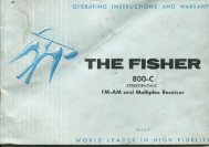
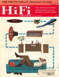
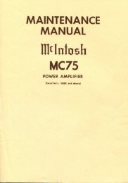
Consider the three cascaded amplifier<br />
stages in (A) of Fig. 15-4. The output<br />
signal voltage coupled from one stage<br />
to the next is that between plate and<br />
ground. While this voltage is almost<br />
equal to the voltage across the plate<br />
resistor at signal frequencies (B+ being<br />
considered as signal ground due to the<br />
effective short of the high capacitance<br />
filters), the reactance of the fi lter capacitors<br />
becomes large enough to be significant<br />
at very low frequencies, and the<br />
above is no longer true. The impedance<br />
between B+ and B- then forms part of<br />
the load impedance of each of the stages,<br />
and this added element of load impedance<br />
is common to all three. Part of the<br />
output voltage of the second and thil'd<br />
stages is thus coupled back to previous<br />
points in the signal channel.<br />
For any two adjacent stages the feedback<br />
is negative-a fraction of the output<br />
signal of the higher level stage is<br />
effectively fed back to its own input,<br />
where the signal, ignoring phase shift,<br />
is exactly opposite in phase. But the<br />
feedback between the first and third<br />
stages is positive. The input signal to the<br />
first stage has suffered two phase reversals,<br />
and the output of the third stage<br />
has the same phase as the output of the<br />
first stage. When the amount of feedback<br />
is great enough, which is to say when<br />
the frequency is low enough for the<br />
filter reactance to have become sufficiently<br />
high, regeneration and self-sustaining<br />
oscillation occur. The subs'onic<br />
frequency of this type of oscillation has<br />
given it the name of motor boating, and<br />
[Continned on page 57J<br />
+ +<br />
... DECOUPUNG<br />
- NETWOOK<br />
I<br />
(s)<br />
,------.1.--- __ ..<br />
, I IMPEDANCE OF .'<br />
I POWER SUPPLY:<br />
II. - - ---r------ ,<br />
-1:-<br />
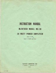
Fig. 15-4. (A) Feedback between stages due to common power supply impedance. (B) Avoid- .<br />
ance of regenerative feedback t hrough the power supply, by the insertion of a de-coupling<br />
network.<br />
AUDIO ENGINEERING • DECEMBER, 1953