abb
Synchrotact 5200 - PM Control
Synchrotact 5200 - PM Control
- No tags were found...

Create successful ePaper yourself
Turn your PDF publications into a flip-book with our unique Google optimized e-Paper software.
3BHS901067 E01 Rev. B<br />
Edition: May 2007<br />
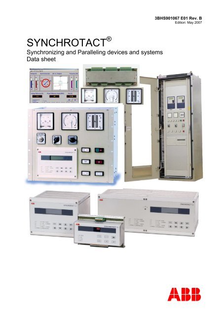
SYNCHROTACT ®<br />
Synchronizing and Paralleling devices and systems<br />
Data sheet<br />
<strong>abb</strong>
Content<br />
SYNCHROTACT ® 5 Synchronizing & Paralleling devices 3<br />
SYNCHROTACT®<br />
SYNCHROTACT ® Accessories 21<br />
SYNCHROTACT ® CSS 29<br />
SYNCHROTACT ® MSP 33<br />
ABB Switzerland Ltd is a world-leading manufacture of synchronization equipment.<br />
Application-oriented solutions are developed, produced, commissioned and serviced.<br />
Advantages<br />
• Maximum reliability<br />
• Guaranteed availability<br />
• Lowest project-engineering costs<br />
• Quick commissioning using convenient PC tool SynView<br />
• Synchronizes up to 7 power circuit breakers with different requirements<br />
• Design 100 % compliant with CE guidelines<br />
• Advanced technology<br />
• Universal use<br />
• Decades of experience with synchronization systems<br />
• After-sales service: 24 h hotline 365 days a year & remote servicing via the internet<br />
• Training program for commissioning and service personnel<br />
An optimum, profit-bringing solution from the very beginning!<br />
3BHS901067 E01
SYNCHROTACT ® 5<br />
Synchronizing and Paralleling devices<br />
SYN 5100<br />
SYN 520v<br />
SYN 5302<br />
3BHS901067 E01
- 4 -<br />
SYNCHROTACT 5<br />
Variety of applications<br />
Synchronization units are widely used in power stations or industrial installations with their own<br />
power generating facilities, where the generators need to be paralleled with an island line or a<br />
public line, or in power distribution systems.<br />
Power circuit breakers may only be closed if both voltages are at least approximately<br />
synchronous (coincident). Otherwise, faults in line operation, loading of the generators and, in<br />
extreme cases, damage to the generators can result.<br />
SYNCHROTACT ® 5 performs these functions safely and reliably, whether as a monitoring<br />
element for manual paralleling or as an independent fully-automatic synchronization unit.<br />
SYNCHROTACT ® 5 covers the following areas of application:<br />
1. Automatic synchronization and paralleling of synchronous generators with line.<br />
U1<br />
SYNCHROTACT 5<br />
CB<br />
G<br />
AVR<br />
GV<br />
U2<br />
U+<br />
U-<br />
f+<br />
f-<br />
COMMAND<br />
S99003<br />
U1 = Line/bus bar-voltage<br />
U2 = Generator voltage<br />
CB = Circuit breaker<br />
G = Generator<br />
AVR = Automatic voltage regulator<br />
GV = Governor<br />
COMMAND = Paralleling command<br />
U+, U- = Voltage adjusting commands<br />
f+, f- = Frequency adjusting commands<br />
2. Automatic paralleling for synchronous and asynchronous lines, transmission lines and<br />
busbars.<br />
U1<br />
SYNCHROTACT 5<br />
CB<br />
COMMAND<br />
U2<br />
S99004<br />
3. Paralleling monitoring (synchrocheck) for the monitoring of automatic or manual paralleling<br />
procedures including the connection of voltage-free lines (dead bus).<br />
U1<br />
SYNCHROTACT 5<br />
CB<br />
U2<br />
CHK<br />
RELEASE<br />
CHK RELEASE = Paralleling command release<br />
G<br />
S99005<br />
3BHS 901 067 E
- 5 -<br />
SYNCHROTACT 5<br />
Typical applications<br />
SYN 5100<br />
SYN5200<br />
Signalization:<br />
Ready<br />
CB<br />
+<br />
Selection<br />
U1<br />
Paralleling release<br />
CB<br />
+<br />
Manual<br />
paralleling switch<br />
U1<br />
Operation<br />
Error<br />
Paralleling release<br />
U2<br />
Release DB<br />
U2<br />
Release DB<br />
Aux. voltage<br />
S99016<br />
AVR = Automatic voltage regulator<br />
GV = Governor<br />
U+<br />
+<br />
AVR<br />
U-<br />
G<br />
f+<br />
+<br />
GV<br />
f-<br />
Aux. voltage<br />
Start<br />
Stop<br />
S99017<br />
Simple, permanently-operated synchrocheck for<br />
paralleling of two lines<br />
Synchrocheck for monitoring manual paralleling of a<br />
generator.<br />
CB<br />
+<br />
SYN 5201/<br />
SYN 5202/<br />
SYN 5302<br />
Signalization:<br />
Ready<br />
U1<br />
Operation<br />
Error<br />
Paralleling command<br />
CB1<br />
+<br />
1<br />
SYN 5500 SYN 5201/<br />
SYN 5202/<br />
SYN 5302<br />
Signalization:<br />
Ready<br />
1<br />
U1<br />
Paralleling command<br />
Operation<br />
Error<br />
U2<br />
Release DB<br />
CB2<br />
+<br />
2<br />
2<br />
1<br />
U2<br />
Release DB<br />
2<br />
Aux. voltage<br />
Aux. voltage<br />
G<br />
AVR<br />
GV<br />
AVR = Automatic voltage regulator<br />
GV = Governor<br />
U+<br />
U-<br />
f+<br />
f-<br />
Start<br />
Stop<br />
S99018<br />
G<br />
AVR<br />
GV<br />
AVR = Automatic voltage regulator<br />
GV = Governor<br />
U+<br />
U-<br />
f+<br />
f-<br />
Start<br />
Stop<br />
1<br />
2<br />
1<br />
2<br />
S99019<br />
Automatic synchronization and paralleling of a<br />
generator.<br />
Automatic synchronization and paralleling of two<br />
power circuit breakers with the same synchronization<br />
unit. The switching can be carried out by means<br />
of the auxiliary device SYN 5500.<br />
3BHS 901 067 E
- 6 -<br />
SYNCHROTACT 5<br />
Clearly-structured principle of operation<br />
The synchronization and paralleling process can be divided into the following blocks:<br />
Measuring<br />
The values voltage difference (amplitude) ΔU, slip (frequency difference) s and phase-angle<br />
difference α, which are required for paralleling, are formed from the two measurement signals<br />
U1 and U2 (see illustration below).<br />
Matching<br />
Voltage and frequency matching functions reduce the voltage difference ΔU and slip s by<br />
sending adjusting pulses to the voltage or turbine regulators.<br />
Monitoring of paralleling conditions<br />
This function compares the actual values with their set maximum values and releases<br />
paralleling (CHK RELEASE) if all conditions are fulfilled simultaneously.<br />
Command generation<br />
The command generation calculates the necessary lead angle αv by which the paralleling<br />
command must be advanced due to the delay through the closing times in order that the main<br />
contacts close exactly at the precise instant of coincidence. If α reaches αv at the same time as<br />
paralleling release (CHK RELEASE), the command is issued. Under synchronous conditions,<br />
i.e. permanent paralleling release during the adjustable monitoring time tsup, the command is<br />
also issued without taking the lead angle into consideration.<br />
SYNCHROTACT 5<br />
Measuring<br />
Matching<br />
U1<br />
|U1|<br />
U+<br />
U+<br />
U2<br />
|U2|<br />
+<br />
-<br />
ΔU<br />
˜0<br />
U-<br />
U-<br />
α<br />
α<br />
α<br />
s<br />
s<br />
α<br />
˜0<br />
f+<br />
f-<br />
f+<br />
f-<br />
Monitoring of paralleling conditions<br />
ΔU<br />
ΔUmax<br />
ΔU
- 7 -<br />
SYNCHROTACT 5<br />
Optimum reliability<br />
From a synchronization unit, It is expected to close the power circuit breaker at the correct time<br />
but also that, if required, paralleling can also take place whenever permissible. Although the<br />
series connection of the output contacts of two independently-functioning channels (dualchannel<br />
system) which is usual in synchronization systems greatly increases security against<br />
incorrect paralleling, it necessarily leads to an reduction in availability.<br />
SYN 5201<br />
Automatic<br />
synchronizing<br />
SYN 5200/SYN 5100<br />
Synchrocheck<br />
SYN 5202<br />
Automatic<br />
synchronizing<br />
Synchrocheck<br />
SYN 5200/SYN5100<br />
Synchrocheck<br />
High levels of safety and reliability can be achieved through the use of a second, redundant synchronizing system. If<br />
system 1 is no longer able to synchronize, it is possible to switch over to the second system and synchronize with<br />
this.<br />
SYN 5302<br />
Automatic<br />
synchronizing<br />
Synchrocheck<br />
II I+II I<br />
Automatic<br />
synchronizing<br />
Synchrocheck<br />
In this configuration, two automatic dual-channel systems are housed in one unit. Normally, the output contacts of<br />
both systems are connected in series (4 channels!). One of the two systems can be bridged by means of a system<br />
selector switch.<br />
Advice:<br />
Single or dual-channel?<br />
Not every synchronization system necessarily needs to be structured according to the above pattern. The<br />
SYNCHROTACT single-channel synchronization units offer a high degree of security and are often used in practice.<br />
However, security can be further increased to a significant degree by means of dual-channel systems. It is unlikely<br />
that the two channels, which are structured differently in both hardware and software terms, will have the same<br />
malfunction simultaneously. The extra cost of a dual-channel system frequently bears a profitable relationship to the<br />
possible consequential costs arising from incorrect paralleling.<br />
Second, redundant synchronizing system?<br />
Often, two redundant synchronizing systems are installed in a plant so that, in the event of failure of one system, it is<br />
possible to switch over to the other and thus increase availability. The second system is often designed for manual<br />
synchronizing with or without synchrocheck.<br />
In addition to this solution, with SYNCHROTACT® 5 ABB offers two automatic dual-channel systems in a single<br />
casing, thus allowing manual synchronization to be dispensed with. The advantages of this solution:<br />
• No engineering and wiring costs for the second system<br />
• Further increased security since all four output contacts are normally operated in series<br />
• No problems with synchronization in cases where the manual synchronizing system is very seldom used.<br />
3BHS 901 067 E
- 8 -<br />
SYNCHROTACT 5<br />
The seven-in-one Synchronizing device!<br />
The specific settings for the synchronization and paralleling are stored in a parameter set.<br />
Devices with 7 parameter sets have seven times the same parameters, with the possibility of<br />
individual setting. That way, seven paralleling points with individual settings may be operated.<br />
First the parameter set or the circuit breaker to be synchronized has to be selected and then the<br />
synchronizing process can be started.<br />
The software-driven link between parameter set and paralleling point guarantees the correct<br />
assignment of the setting values to the related plant components.<br />
Parameter set 1<br />
2<br />
3<br />
4<br />
5<br />
6<br />
7<br />
1<br />
2<br />
3<br />
4<br />
5<br />
6<br />
7<br />
Parameter<br />
select switches<br />
Parameter<br />
set selection<br />
1<br />
2<br />
3<br />
4<br />
5<br />
6<br />
7<br />
S00016<br />
Possible means of control<br />
Service control for commissioning and servicing:<br />
1. Built-in service controls: keypad & LCD (standard)<br />
2. SynView PC tool (accessory) for local control: PC/Ethernet (standard)<br />
3. SynView PC tool (accessory) via LAN (standard)<br />
Operating control for normal synchronizing operation:<br />
1. Digital inputs/outputs: conventional wiring (standard)<br />
2. Interface (modbus, profibus, LON): remote-controlled synchronizing operation (option)<br />
3BHS 901 067 E
- 9 -<br />
SYNCHROTACT 5<br />
Device types<br />
The SYNCHROTACT ® 5 family of devices consists of 5 device types:<br />
Type Function Symbol<br />
SYN5100<br />
SYN 5100<br />
Synchrocheck<br />
Synchrocheck<br />
S99008<br />
SYN 5200<br />
Synchrocheck or automatic<br />
paralleling unit without matcher<br />
SYN5200<br />
Synchrocheck<br />
S99009<br />
SYN 5201<br />
Automatic single-channel<br />
synchronization unit<br />
SYN5201<br />
automatic<br />
Synchronizer<br />
S99010<br />
SYN 5202<br />
Automatic dual-channel<br />
synchronization unit<br />
SYN5202<br />
automatic<br />
Synchronizer<br />
Synchrocheck<br />
S99011<br />
SYN 5302<br />
Redundant automatic dualchannel<br />
synchronization unit<br />
SYN5302<br />
automatic<br />
Synchronizer<br />
Synchrocheck<br />
II<br />
I+II<br />
I<br />
automatic<br />
Synchronizer<br />
Synchrocheck<br />
S99012<br />
Difference between SYN 5302 and SYN 5202:<br />
The SYN 5202 is a dual-channel system with two differently-structured independent channels in the same casing.<br />
SYN 5302 consists of two SYN 5202 dual-channel devices in one casing. The two systems are normally all wired in<br />
series (4 channels!). In the event of failure of one system, it is possible to switch over without danger to the other<br />
dual-channel automatic system. This allows paralleling to be carried out fully automatically and with maximum<br />
security at all times. Additional costs for a redundant synchronization system are saved.<br />
Difference between SYN 5100 and SYN 5200:<br />
SYN 5100 offers a parameter set with 5 parameters, the auxiliary voltage range is 50 to 130 VAC or 100 to<br />
125 VDC.<br />
SYN 5200 features communications interfaces, seven parameter sets, a wider auxiliary voltage range and the<br />
convenient PC tool SynView with all its functions. In addition, because of its command generation, SYN 5200 can<br />
also be used as an automatic paralleling unit.<br />
Type code<br />
SYN 5202<br />
Synchronization type<br />
00: Synchrocheck<br />
01: Single-channel device<br />
02: Dual-channel device<br />
Construction size<br />
1: Small size<br />
2: Medium size<br />
3: Large size<br />
SYNCHROTACT<br />
SYN = SYNCHROTACT<br />
5: Fifth generation<br />
3BHS 901 067 E
- 10 -<br />
SYNCHROTACT 5<br />
Device types<br />
SYN 5100:<br />
Front view of SYN 5200, SYN 5201, SYN 5202:<br />
Rear view of SYN 5202 with 7 parameter sets:<br />
Front view of SYN 5302:<br />
Rear view of SYN 5302 with 7 parameter sets:<br />
3BHS 901 067 E
- 11 -<br />
SYNCHROTACT 5<br />
Scope of functions at a glance<br />
Function<br />
Type<br />
SYN 5100 SYN 5200 SYN 5201 SYN 5202 SYN 5302<br />
Automatic synchronization No Yes Yes Yes Yes<br />
Paralleling of two lines Yes Yes Yes Yes Yes<br />
Synchrocheck mode Yes Yes Yes Yes Yes<br />
Voltage matching No No Yes Yes Yes<br />
Frequency matching No No Yes Yes Yes<br />
Dual channel system No No No Yes Yes<br />
Integrated, redundant system (bypass) No No No No Yes<br />
Number of parameter sets 1 either 1 or either 1 or either 1 or either 1 or 7<br />
7<br />
7<br />
7<br />
Paralleling of synchronous lines Yes Yes Yes Yes Yes<br />
Paralleling of asynchronous lines Yes Yes Yes Yes Yes<br />
Paralleling of voltage-free lines Yes Yes Yes Yes Yes<br />
Signalling No Yes Yes Yes Yes<br />
Parameter setting by PC-Tool SynView No Yes Yes Yes Yes<br />
Parameter setting without PC Yes Yes Yes Yes Yes<br />
Semi-flush mounting No Yes Yes Yes Yes<br />
Surface mounting No on request on request on request on request<br />
Hat rail mounting (DIN) Yes No No No No<br />
Options<br />
Option SYN 5100 SYN 5200, SYN 5201, SYN 5202,<br />
SYN 5302<br />
w<br />
Communication<br />
(Operating interface)<br />
0 none 0 none<br />
2 Modbus<br />
3 Profibus<br />
4 Lon-Bus<br />
x Code for internal use 2 internal code 2 internal code<br />
y<br />
Auxiliary voltage<br />
/ nominal frequency<br />
Un = 50 to 130 VAC & 100 to 125 VDC:<br />
2 fn = 50/60 Hz<br />
5 fn = 16 2 / 3 Hz<br />
Un = 100 to 230 VAC & 24 to 250 VDC:<br />
7 fn = 50/60 Hz<br />
8 fn = 16 2 / 3 Hz<br />
z Parameter sets 1 1 Parameter set 1 1 Parameter set<br />
7 7 Parameter sets<br />
Ordering details<br />
Device type<br />
SYN 5u0v<br />
Options<br />
- wxyz<br />
Examples:<br />
SYN 5100 – 0221 Synchrocheck with nominal frequency 50 or 60 Hz and 1 parameter set<br />
SYN 5200 – 0271 Synchrocheck with nominal frequency 50 or 60 Hz and 1 parameter set<br />
SYN 5201 – 0287 Automatic single-channel synchronization unit with nominal frequency 16 2 / 3 Hz and 7<br />
parameter sets<br />
SYN 5202 – 2277 Automatic dual-channel synchronization unit with communication (Modbus), nominal<br />
frequency 50 or 60 Hz and 7 parameter sets<br />
SYN 5302 – 4277 Redundant automatic dual-channel synchronization unit with communication (LON),<br />
nominal frequency 50 or 60 Hz and 7 parameter sets<br />
3BHS 901 067 E
- 12 - SYNCHROTACT 5<br />
Captions to the options<br />
Option w: Communication (Operating interface)<br />
Characteristics of the operating remote control:<br />
Supported protocols: Modbus RTU; Profibus; Lon<br />
Interface type: Modbus and Profibus: RS 485<br />
Lon: optical<br />
Connector type: Modbus and Profibus: D-Sub9 (female)<br />
Lon: HP BFOC/2,5 (optical)<br />
Transmitted signals: Digital inputs/outputs; status indicators (LEDs); actual values (analogue); new event<br />
Addressing:<br />
Slave address, depending on fieldbus<br />
SYN 5302: the interfaces are duplicated, i.e. each system can be controlled individually.<br />
Commands, for example starting synchronizing, have to be given separately for each system.<br />
Option z: Parameter sets<br />
SYNCHROTACT 5 - devices with 7 parameter sets include additional hardware with seven<br />
digital inputs and seven relay outputs. They are normally used for the selection of both,<br />
parameter set and paralleling point. The inputs and outputs not used can be configured for other<br />
functions. The possible functions are shown in the table below:<br />
Configurable functions of digital inputs<br />
Selection of parameter set or paralleling point<br />
Selection of TEST mode<br />
Starting, stopping and blocking of synchronization process<br />
Reset of the device<br />
Configurable functions of digital outputs<br />
Selection or acknowledgement of paralleling point/ parameter set<br />
Switchover contact for the command circuit which must be connected in<br />
series with the manual paralleling circuit in synchrocheck mode<br />
Signalling of the following variables:<br />
Paralleling command in TEST mode<br />
Dead bus released<br />
Synchronization process stopped<br />
Phase-angle difference within tolerance band<br />
Slip within tolerance band<br />
Voltage difference within tolerance band<br />
Paralleling command released<br />
U1 leading or lagging<br />
f1>f2; f1U1; U2
- 13 -<br />
SYNCHROTACT 5<br />
Construction<br />
SYN 5100:<br />
ABB SYNCHROTACT<br />
®<br />
5<br />
128<br />
ΔU
- 14 -<br />
SYNCHROTACT 5<br />
SYN 5302:<br />
SYNCHROTACT ®<br />
5<br />
I+II<br />
I II<br />
U+<br />
U-<br />
ΔU
- 15 - SYNCHROTACT 5<br />
Technical data<br />
INPUTS<br />
Auxiliary voltage<br />
Nominal voltage range<br />
Permissible voltage range<br />
SYN 520v/SYN 5302<br />
Maximum power consumption<br />
SYN 5100<br />
Maximum power consumption<br />
Measuring inputs U1, U2<br />
Digital inputs<br />
OUTPUTS<br />
Nominal voltage range<br />
Voltage range<br />
Nominal frequency<br />
Frequency range<br />
Nominal voltages<br />
Current consumption<br />
READY<br />
OPERATING<br />
24 to 250 VDC<br />
100 to 230 VAC<br />
18 to 300 VDC<br />
75 to 300 VAC<br />
25 W/35 VA<br />
25 W/35 VA<br />
2 W/4 VA<br />
50 to 130 VAC<br />
0 to 130 % Un<br />
16 2 / 3 , 50, 60 Hz<br />
10 to 100 Hz<br />
24/48 VDC<br />
6 to 8 mA<br />
Paralleling relays<br />
Maximum contact voltage<br />
Limiting continuous current<br />
Maximum switching power ON AC/DC<br />
Maximum switching power OFF AC/DC (resistive)<br />
Adjusting command and signalling relays<br />
Maximum contact voltage<br />
Limiting continuous current<br />
Maximum switching power ON/OFF AC/DC<br />
250 VAC/VDC<br />
10 A<br />
1500 VA/W<br />
1500/150 VA/W<br />
250 VAC/VDC<br />
1.5 AAC/ADC<br />
50 VA/W<br />
INTERFACE<br />
PC-Tool ‘SynView‘ Ethernet<br />
Bridgeable distance<br />
100 m<br />
3BHS 901 067 E
- 16 - SYNCHROTACT 5<br />
PARAMETER SETTING RANGES<br />
SYN 5200, SYN 5201, SYN 5202 (channel 1), SYN 5302 (channels 1)<br />
Actual value calibration Step Setting range<br />
Nominal voltage 1 V 50 to 130 VAC<br />
Voltage matching (between U1 & U2) 0.1 % ±12 %<br />
Angle matching (SYN 5200 & SYN 5201 only) 1 DEG ±180 DEG<br />
Command generation<br />
Paralleling time 10 ms 0 to 990 ms<br />
Duration of paralleling command 10 ms 50 to 990 ms<br />
Monitoring time 1 s 0 to 99 s<br />
Paralleling conditions<br />
Slip limit* 0,01 % 0 to 6 %<br />
Angle limit (angle window)* 1 DEG 1 to 99 DEG<br />
Maximum voltage difference* 1 % 0 to 40 %<br />
Maximum voltage 1 % 100 to 130 %<br />
Minimum voltage 1 % 50 to 95 %<br />
* Positive and negative limit values can be set separately.<br />
Dead bus conditions<br />
Note:<br />
Voltage matcher<br />
Maximum zero voltage for dead bus 1 % 0 to 49 %<br />
The following possibilities - and all combinations thereof - can be allowed or ruled out for<br />
paralleling by means of programming: U1 = dead bus; U2 = dead bus; both sides dead bus<br />
Voltage adjustment characteristic 0.01 %/s 0 to 5 %/s<br />
Interval between pulses 1 s 1 to 20 s<br />
Minimum pulse duration 0,01 s 0.05 to 2 s<br />
Note: The length of adjusting pulses are proportional to the voltage difference. The proportionality factor (0.01<br />
to 5 %/s) is adjustable. Alternatively, it is possible to work with fixed pulse lengths (0.05 to 2 s), in which<br />
case the interval times are inversely proportional to the voltage difference.<br />
Frequency matcher<br />
Note:<br />
Frequency adjustment characteristic 0.01 %/s 0 to 5 %/s<br />
Interval between pulses 1 s 1 to 120 s<br />
Minimum pulse duration 0.01 s 0.05 to 2 s<br />
The length of adjusting pulses are proportional to the slip. The proportionality factor (0.01 to 5 %/s) is<br />
adjustable. Alternatively, it is possible to work with fixed pulse lengths (0.05 to 2 s), in which case the<br />
interval times are inversely proportional to the slip.<br />
General parameters<br />
Blocking time following start signal 1 s 1 to 10 s<br />
Total paralleling time 0.5 min 0.5 to 15 min; OFF<br />
SYN 5100, SYN 5202 (channel 2), SYN 5302 (channels 2)<br />
Note:<br />
Slip limit 0.1 % 0.1 to 2 %<br />
Angle limit 5 DEG 5 to 40 DEG<br />
Maximum voltage difference 5 % 5 to 40 %<br />
Maximum zero voltage for dead bus 5 % 0 to 50 %<br />
Nominal voltage 5 V 50 to 130 VAC<br />
The percentages refer to the nominal values<br />
3BHS 901 067 E
- 17 - SYNCHROTACT 5<br />
ENVIRONMENTAL VALUES<br />
Isolation<br />
Dielectric test IEC 60255-5 2 kV<br />
Impulse voltage test IEC 60255-5 5 kV<br />
Temperature ranges for devices without communication<br />
Transport/storage -40 to +85 °C<br />
Functionable -25 to +70 °C<br />
Operation (compliance with technical data) -10 to +55 °C<br />
Temperature ranges for devices including communication<br />
Transport/storage -10 to +85 °C<br />
Functionable +5 to +70 °C<br />
Operation (compliance with technical data) +5 to +55 °C<br />
Mechanical stability<br />
Vibration<br />
Vibration response<br />
Endurance<br />
Shocks and Bumps<br />
Shock response<br />
Withstand<br />
Bump<br />
Earthquake<br />
Single axis sine sweep seismic<br />
test<br />
IEC 60255-21-1 10 to 150 Hz; cl. 2<br />
1 g<br />
2 g<br />
IEC 60255-21-2 class 2<br />
10 g<br />
30 g<br />
20 g<br />
IEC 60255-21-3<br />
IEEE STD 344-1987<br />
Method A<br />
5g in each axis<br />
Emission/immunity (EMC)<br />
Emission AC mains<br />
conducted disturbance<br />
Emission, enclosure<br />
radiation disturbance<br />
CISPR 22<br />
CISPR 11<br />
Electrostatic discharges IEC 60255-22-2<br />
IEC 61000-4-2<br />
IEEE C37.90.3-2001<br />
Class B<br />
0.15 to 0.5 MHz:<br />
66..56 dB/56..46 dB<br />
0.5 to 5 MHz: 56 dB / 46 dB<br />
5 to 30 MHz: 60 dB / 50 dB<br />
Class A<br />
30 to 230 MHz: 30 dB<br />
230 to 1000MHz: 37 dB<br />
Class IV<br />
Contact: 8 kV<br />
Air: 15 kV<br />
3BHS 901 067 E
- 18 - SYNCHROTACT 5<br />
Electromagnetic fields IEC 61000-4-16<br />
IEC 61000-4-6<br />
IEC 60255-22-3<br />
IEC 61000-4-3<br />
IEEE C37.90.2-2004<br />
Fast transient IEC 60255-22-4<br />
IEC 61000-4-4<br />
IEEE C37.90.1-2002<br />
(fast transient)<br />
0 to 150 kHz: 30 V continuous<br />
300 V; for 1 s<br />
0,15 to 80 MHz<br />
10 V; 80 % AM<br />
Frequency sweep:<br />
80 to 1000 MHz: 10 V/m; 80 % AM<br />
1.4..2 GHz: 20 V/m; 80 % AM<br />
Spot frequencies:<br />
80/160/450/900 MHz: 80 % AM;<br />
Testing time >10 s<br />
25 to 1000 MHz: 20 V/m; 80% AM<br />
(max. result. field strength: 35 V/m)<br />
Class IV; 4 kV<br />
4 kV common & transverse mode<br />
IEC 61000-4-12 2.5 kV<br />
Surge voltage IEC 61000-4-5 Installation classification: class 3<br />
±1 / ±2 kV<br />
Voltage dips IEC 61000-4-11 AC:<br />
30 %: 10 ms<br />
60 %: 100 ms<br />
>95 %: 5000 ms<br />
1 MHz Burst disturbance IEC 60255-22-1 Class III<br />
2.5 kV common & transverse<br />
IEEE C37.90.1-2002 2.5 kV common & transverse<br />
("oscillatory")<br />
3BHS 901 067 E
- 19 - SYNCHROTACT 5<br />
RELEVANT STANDARDS<br />
CE-conformity<br />
EMC-Directive:<br />
Generic standard<br />
89/336/EEC<br />
EN 50081-2<br />
EN 50082-2<br />
Emission<br />
Immunity<br />
Product standards<br />
LV-Directive:<br />
Safety of information technology<br />
equipment<br />
Measuring relays and protection<br />
equipment<br />
73/23/EEC<br />
EN 60950<br />
IEC 60255-6<br />
Product standard for measuring<br />
relays and protection equipment<br />
Hydro Québéc standard for<br />
electronic equipment and relays<br />
IEEE standard for relays<br />
EN 50263<br />
SN-62.1008d<br />
IEEE C37.90-1989<br />
CONSTRUCTION DATA<br />
Degrees of protection in accordance to IEC 60529<br />
Dimensions<br />
SYN 5100<br />
Front IP 54<br />
Rear IP 50<br />
Modular casing designed to snap onto rail<br />
SYN 520x<br />
SYN 5302<br />
SYN 5500<br />
Casing size (WxHxD)<br />
Modular casing designed to snap onto rail<br />
Weight<br />
see illustration of<br />
dimensions<br />
see illustration of<br />
dimensions<br />
see illustration of<br />
dimensions<br />
381*128*50 mm<br />
SYN 5100<br />
SYN 5200 (maximum variant)<br />
SYN 5302<br />
0.3 kg<br />
4 kg<br />
8 kg<br />
3BHS 901 067 E
- 20 - SYNCHROTACT 5<br />
Spare parts<br />
PCB designation<br />
Type<br />
Communications board SYN 5010<br />
Processor and power supply board (Indication of device type required, e.g. SYN 5201) SYN 5011<br />
Basic I/O unit SYN 5012<br />
Processor for channel 2 (synchrocheck) SYN 5013<br />
Extended I/O / 7 parameter sets (option) SYN 5014<br />
Bus board for SYN 520x SYN 5015<br />
System control SYN 5020<br />
Bus board for SYN 5302 SYN 5025<br />
Ordering information:<br />
When ordering, please state the complete type designation of the synchronizing unit.<br />
Recommendation:<br />
No individual parts are available for the SYN 5100 unit. It is therefore recommended that an identical, pre-set<br />
replacement unit be kept in store.<br />
In the case of SYN 520x units, it is recommended that an identical, pre-set replacement unit be kept in store.<br />
In the case of the SYN 5302, the following PCB modules are recommended as spare parts: SYN 5020 system control<br />
and SYN 5014 extended I/O card, if the latter is installed.<br />
3BHS 901 067 E
SYNCHROTACT ®<br />
Accessories<br />
SynView<br />
SYN 5500<br />
Instruments<br />
Adaptation VT's<br />
3BHS 901 067 E
- 22 - SYNCHROTACT Accessories<br />
Fast commissioning with SynView<br />
SynView is the appropriate aid for simple and fast commissioning of SYNCHROTACT ® 5<br />
devices. The PC software runs under MS ® Windows NT, 95, 98, 2000 and XP in the standard<br />
languages German, English or French. Versions in other languages are possible. SynView<br />
consists of 5 functions which are explained in greater detail in the following.<br />
Parameter tool<br />
All parameter settings are carried out with<br />
this. The files can be stored on the PC and<br />
copied to other units. Helpful functions such<br />
as comparing parameter files with device<br />
settings or the display of recommended<br />
setting values greatly simplify commissioning<br />
and servicing work .<br />
Transient recorder tool<br />
The voltage difference and paralleling<br />
command from the last three synchronizing<br />
processes are displayed. The tool makes the<br />
use of a separate recorder unnecessary.<br />
Actual values tool<br />
A synchroscope, together with all the values<br />
important for paralleling, is displayed on the<br />
user interface. These simplify function-testing<br />
of the synchronizing process if no instruments<br />
are available.<br />
Fault-/Event log tool<br />
The 256 events stored in SYNCHROTACT ® 5<br />
are displayed in plain text with date and<br />
timestamp. This greatly simplifies the<br />
localization of faults, e.g. wiring or control<br />
faults which sometimes occur during<br />
commissioning.<br />
Diagnostic tool<br />
In difficult cases which cannot be solved on<br />
site, this tool helps the manufacturer to identify<br />
the causes of the problem from the data<br />
stored here.<br />
Ordering details<br />
Designation Type Part no<br />
PC-Tool for commissioning and maintenance SynView 3BHE 021 768 R0002<br />
3BHS 901 067 E
- 23 - SYNCHROTACT Accessories<br />
Auxiliary device SYN 5500<br />
The auxiliary device SYN 5500 performs the connection of the measuring and command circuits<br />
where several paralleling points need to be switched. An SYN 5500 device can switch 2<br />
paralleling points, each with a maximum of 16 contact pairs, or alternatively, 4 paralleling points,<br />
each with 8 contact pairs. Several devices can be used in combination.<br />
CB1<br />
+<br />
SYN 5500 SYN 5201/<br />
SYN 5202/<br />
SYN 5302<br />
Signalization:<br />
Ready<br />
1<br />
1<br />
U1<br />
Operation<br />
Error<br />
Paralleling command<br />
CB2<br />
+<br />
2<br />
2<br />
1<br />
U2<br />
Release DB<br />
2<br />
Aux. voltage<br />
G<br />
AVR<br />
GV<br />
AVR<br />
GV<br />
= Automatic voltage regulator<br />
= Governor<br />
U+<br />
U-<br />
f+<br />
f-<br />
Start<br />
Stop<br />
1<br />
2<br />
1<br />
2<br />
S99019<br />
Ordering details<br />
Designation Type Part no<br />
Auxiliary device for switching several paralleling SYN 5500 3BHB 006 500 R0001<br />
points<br />
Technical Data<br />
Maximum contact voltage<br />
Limiting continuous current<br />
Maximum switching power ON AC/DC<br />
Maximum switching power OFF AC/DC (resistive)<br />
Coil nominal voltage<br />
Operate voltage<br />
Release voltage<br />
Coil resistance<br />
Coil inductivity<br />
250 VAC/VDC<br />
10 A<br />
1500 VA/W<br />
1500/150 VA/W<br />
24 VDC<br />
≥18 VDC<br />
≤3.6 VDC<br />
1152 Ω<br />
1000 mH<br />
3BHS 901 067 E
- 24 - SYNCHROTACT Accessories<br />
Synchronizing instruments<br />
Electromechanical instruments are commonly used if the synchronizing system provides a<br />
manual synchronization feature. Sometimes the instruments are used in automatic<br />
synchronizing systems for information only, e.g. for servicing purposes. This case can also be<br />
covered by the SYNCHROTACT ® 5 PC-tool ‘SynView‘.<br />
Options<br />
Option<br />
Code<br />
w Nominal voltage 1 100/√3 = 57.7 V<br />
2 110/√3 = 63.5 V<br />
3 115/√3 = 66.4 V<br />
4 120/√3 = 69.3 V<br />
5 100 V<br />
6 110 V<br />
7 115 V<br />
8 120 V<br />
x Nominal frequency 5 50 Hz<br />
6 60 Hz<br />
y Labeling 1 Standard labeling<br />
2 Labeling according to separate specification<br />
z Size 0 96*96 mm<br />
1 144*144 mm<br />
Ordering details<br />
Designation Type Part no<br />
Double volt meter<br />
SYN 5U96-wxy0<br />
SYN 5U144-wxy1<br />
3BHE022'313Rwxy0<br />
3BHE022'313Rwxy1<br />
Double frequency meter<br />
SYN 5F96-wxy0<br />
SYN 5F144-wxy1<br />
3BHE022'314Rwxy0<br />
3BHE022'314Rwxy1<br />
Synchroscope<br />
SYN 5S96-wxy0<br />
SYN 5S144-wxy1<br />
3BHE022'315Rwxy0<br />
3BHE022'315Rwxy1<br />
General technical data<br />
Isolation IEC 60255-5 2 kV<br />
Temperature range Operation -25 °C to +40 °C<br />
Storage -25 °C to +65 °C<br />
Relative humidity<br />
≤75 % annual average,<br />
no condensation<br />
Shock<br />
15 g, 11 ms<br />
Vibration<br />
2.5 g, 5 to 55 Hz<br />
Protection degree casing IEC 60529 IP 54<br />
connections IEC 60529 IP 00<br />
Dimensions width * height * installation depth Size 96<br />
96 * 96 *115 mm<br />
Size 144<br />
144 * 144 * 164 mm<br />
Front frame 96 / 144 96 mm / 144 mm<br />
Casing 96 / 144 90 mm / 136 mm<br />
Panel cut-out 96 / 144 92 +0,8 mm / 138 +1 mm<br />
3BHS 901 067 E
- 25 - SYNCHROTACT Accessories<br />
Fixing<br />
Electrical connections<br />
Screw clamps<br />
Screw-type terminals<br />
Technical data double volt meter<br />
Measuring range voltage<br />
0 to 120 % Un<br />
Scale arrangement<br />
vertical<br />
Power consumption with Un ≤ 110 V 96: 2*
- 26 - SYNCHROTACT Accessories<br />
Adaptation and compensation VT's<br />
When are adaptation or compensation VT's needed?<br />
• If the two nominal measuring voltages are out of admissible range (50 to 130 VAC).<br />
• If the two nominal measuring voltages are different. With the types SYN 5200 and<br />
SYN 5201, differencies of the nominal values up to 10 % can be tuned by parameter setting.<br />
• If there is a step up transformer between measuring VT and circuit breaker, which shifts the<br />
phase by a fixed value, it can be compensated with types SYN 5200 and SYN 5201. With<br />
the types SYN 5100, SYN 5202, SYN 5302, or with the use of electromechanical<br />
synchronizing instruments, compensation VT's shall be used in order to compensate the<br />
phase shift.<br />
Hints to select compensation VT's<br />
If possible the compensation should be done in a way that a single phase compensation VT is required only:<br />
U1<br />
VT 1<br />
110 V/1.73<br />
L1 - N<br />
63.5 V<br />
If there is a step up transformer between measuring VT and<br />
circuit breaker, the connection group is usually Yd1<br />
(+30 DEG) or Yd11 (-30 DEG).<br />
Step up transformer<br />
Yd1 (+30 DEG)<br />
or<br />
Yd11 (-30 DEG)<br />
With the appropriate selection of the phases, the phase shift<br />
can be compensated without any additional components. In<br />
this example the compensation of the amplitude by factor √3<br />
remains. This can be done by a single phase compensation<br />
VT.<br />
In order to achieve higher accuracy, especially if higher load<br />
(synchronizing instruments) is connected, the compensation<br />
should be carried out on the generator side.<br />
CB<br />
U2<br />
VT 2<br />
110 V 30°<br />
110 V<br />
If a three phase compensation is inevitable, 3 single phase<br />
VT's have to be selected which will then be connected<br />
according to the needs. Be aware that the single phase ratio<br />
has to be calculated.<br />
G<br />
3BHS 901 067 E
- 27 - SYNCHROTACT Accessories<br />
Ordering details<br />
Designation Type Part no<br />
Single phase VT SYN 5T66-0001 3BHE024'870R0001<br />
Dimensioned drawing / connection diagram<br />
Examples<br />
Example Ratio Connection Example Ratio Connection<br />
100 V -> 100 V<br />
110 V -> 110 V<br />
120 V -> 120 V<br />
63,5 V -> 63,5 V<br />
57,7 V -> 57,7 V<br />
1 2-4 A-C<br />
110 V -> 100 V<br />
0,909 1-4 A-C 100 V -> 110 V 1,1 A-C 1-4<br />
100 V -> 57,7 V<br />
110 V -> 63,5 V<br />
120 V -> 69,3 V<br />
1/√3 =<br />
0,577<br />
2-4 B-C 57,7 V -> 100 V<br />
63,5 V -> 110 V<br />
69,3 V -> 120 V<br />
√3 = 1,73 B-C 2-4<br />
100 V -> 63,5 V<br />
1,1/√3 =<br />
0,635<br />
3-4 B-C 63,5 V -> 100 V √3/1,1 =<br />
1,57<br />
B-C 3-4<br />
110 V -> 57,7 V<br />
1/(1,1*√3)<br />
=<br />
0,525<br />
1-4 B-C 57,7 V -> 110 V 1,1*√3 =<br />
1,91<br />
B-C 1-4<br />
Technical data<br />
Nominal voltage range primary & secondary<br />
Accuracy / power w/o synchronizing instruments<br />
Accuracy / power with synchronizing instruments<br />
57.7 to 120 VAC<br />
Class 1 / 0.05 VA<br />
Class 2 / 4 VA<br />
Class 5 / 7.5 VA<br />
Dimensions w * h * d 66 * 81 * 88 mm<br />
Weight<br />
1.0 kg<br />
3BHS901067 E01
3BHS901067 E01
SYNCHROTACT ®<br />
Synchronizing systems<br />
SYNCHROTACT CSS<br />
3BHS901067 E01
- 30 - SYNCHROTACT CSS<br />
Application<br />
The use of the already planned and tested synchronizing system saves all project planning<br />
costs and inreases the safety of the plant. SYNCHROTACT ® CSS only needs to be installed,<br />
connected and commissioned.<br />
The system uses the proven and reliable SYNCHROTACT ® 5 - components and is suitable to<br />
be built into a 19"-frame.<br />
To ensure high availability of the plant SYNCHROTACT ® CSS consists of a fully automatic and<br />
an independent manual synchronizing.<br />
Different versions are available either for one or for two circuit breakers and both either in single<br />
or dual channel configuration.<br />
The PC software SynView which is included with the delivery allows commissioning to be<br />
carried out quickly and simply.<br />
Functionality<br />
SYNCHROTACT ® CSS supports the following operating modes, which can be selected by<br />
means of a selector switch.<br />
• Operating mode AUTO: generator voltage and frequency are automatically matched by the<br />
synchronizing equipment. The circuit breaker will be closed subsequently and exactly with<br />
phase-coincidence, taking the breaker closing time into consideration.<br />
• Operating mode MAN: the functions are carried out manually by means of push buttons on<br />
the front panel. The necessary values are displayed on the synchronizing instruments. The<br />
paralleling command is issued by holding down the releasing button and pushing the<br />
command button if phase-coincidence is reached.<br />
• Die Operating mode TEST is identical with the AUTO-mode, except the paralleling<br />
command which is not sent to the circuit breaker but displayed by the system only.<br />
With models for two circuit breakers the paralleling point has to be selected by means of the<br />
appropriate selector switch before the synchronizing process is started.<br />
By releasing by means of a key switch, the circuit breaker can be closed even if one or both<br />
measuring voltages are dead (Dead bus).<br />
Changing the control mode selection from «local» to «remote» allows to use automatic<br />
synchronizing from remote location.<br />
3BHS901067 E01
- 31 - SYNCHROTACT CSS<br />
Versions<br />
Type Function Symbol<br />
CSS-1100<br />
Single channel system<br />
for one circuit breaker<br />
CSS-1200<br />
Single channel system<br />
for two circuit breakers<br />
CSS-2100<br />
Dual channel system<br />
for one circuit breaker<br />
CSS-2200<br />
Dual channel system<br />
for two circuit breakers<br />
Ordering details<br />
CSS - Type:<br />
Single/dual channel system and 1/2 circuit breaker<br />
Auxiliary voltage:<br />
Nominal value<br />
Measuring voltage: Primary/Secondary nominal values and nominal frequency<br />
Synchronizing instruments: Labelling: primary, secondary or percentage values and language<br />
Example:<br />
SYNCHROTACT CSS-2100<br />
Auxiliary voltage: 110 VDC<br />
Measuring voltage: 11kV/110 VAC, 50 Hz<br />
Synchronizing instruments: primary values;<br />
english<br />
Dual channel synchronizing system for one circuit breaker<br />
Auxiliary voltage: 110 VDC and measuring voltage primary<br />
11 kV, secondary 110 V and 50 Hz nominal frequency<br />
Double voltmeter labelled with primary values and<br />
synchroscope labelled in english<br />
3BHS901067 E01
- 32 - SYNCHROTACT CSS<br />
Technical Data<br />
Auxiliary voltage<br />
Nominal voltage range<br />
Permissible voltage range<br />
Maximum power consumption<br />
Measuring inputs<br />
Nominal voltage range<br />
Voltage range<br />
Nominal frequency<br />
Frequency range<br />
110 to 220 VAC/VDC<br />
85 to 265 VAC<br />
85 to 375 VDC<br />
25 W/35 VA<br />
50 to 130 VAC<br />
0 to 110 % Un<br />
16 2 / 3 , 50, 60 Hz<br />
10 to 100 Hz<br />
OUTPUTS and PARAMETER SETTING RANGES<br />
Refer to SYNCHROTACT 5<br />
ENVIRONMENTAL VALUES<br />
Isolation<br />
Dielectric test IEC 60255-5 2 kV<br />
Impulse voltage withstand test IEC 60255-5 5 kV<br />
Temperature ranges<br />
Transport/storage -25 to +65 °C<br />
Operation -25 to +40 °C<br />
Interference immunity/transmission (EMC)<br />
Refer to SYNCHROTACT 5<br />
RELEVANT STANDARDS<br />
CE conformity<br />
EMC directive:<br />
Generic standard<br />
89/336/EEC<br />
EN 50081-2<br />
EN 50082-2<br />
Emission<br />
Immunity<br />
Product standards<br />
Low voltage directive:<br />
Safety of information technology<br />
equipment<br />
73/23/EEC<br />
EN 60950<br />
Measuring relays & protection equipment IEC 60255-6<br />
CONSTRUCTION DATA<br />
Protection type according to IEC 60529<br />
Front IP 50<br />
Rear IP 00<br />
Dimensions<br />
Width*height*depth<br />
482*399*297 mm<br />
Weight<br />
Depending on the version<br />
15 to 16 kg<br />
3BHS901067 E01
SYNCHROTACT ®<br />
Synchronizing systems<br />
SYNCHROTACT MSP<br />
3BHS901067 E01
- 34 - SYNCHROTACT MSP<br />
Application<br />
SYNCHROTACT ® MSP (Modular Synchronizing Panel) is a modular synchronizing system to<br />
synchronize generators and to parallel lines, built into a cubicle.<br />
The measuring and metering feature, which is available in addition to the synchronizing system<br />
uses space conditions and already available signals in an optimum way.<br />
The SYNCHROTACT® MSP includes:<br />
SYNCHROTACT 5 Synchronizing system<br />
• Automatic single or dual channel synchronizing system<br />
• Manual synchronizing by means of a synchrocheck<br />
• Local control panel<br />
Electrical measuring and metering system<br />
• Measuring system using transducers<br />
• Metering system using power and energy meters<br />
3BHS 901 067 E
- 35 - SYNCHROTACT MSP<br />
Functionality of Synchronizing<br />
The system uses the proven and reliable SYNCHROTACT ® 5 - components. Basically the<br />
synchronizing part includes an automatic and a redundant synchronizing feature (automatic or<br />
manual).<br />
The modular concept allows to adapt the synchronizing system individually. The following<br />
options are available:<br />
1. Safety: single or dual channel solutions<br />
2. Availability: redundant manual synchronizing or redundant automatic synchronizing or<br />
both<br />
3. Number of circuit breakers to be synchronized: 1 to 4 CB's, one or more of them may be<br />
generator breakers<br />
4. Power supply: in case of a redundant synchronizing, the power supply on the cubicle<br />
entrance can be redundant too.<br />
5. Control: The control of the synchronizing is possible from remote in any case. An<br />
alternative local control is available as an option.<br />
6. Adaptation of the measuring voltages: especially with synchronizing of several circuit<br />
breakers it may occur that the two secondary voltages have different amplitudes and<br />
phase angles with closed circuit breaker.<br />
3BHS 901 067 E
- 36 - SYNCHROTACT MSP<br />
Synchronizing concept<br />
Regarding availability, different solutions are possible:<br />
Automatic synchronizing (sketch shows dual channel version) including separate synchrocheck<br />
for redundant manual synchronizing (with its own hardware and power supply)<br />
Automatic synchronizing (sketch shows dual channel version) using parameter set 7 as<br />
synchrocheck for manual synchronization.<br />
Redundant, automatic dual channel synchronizing with the additional possibility of a manual<br />
synchronization (using parameter set 7)<br />
The PC software SynView which is included with the delivery allows commissioning to be<br />
carried out quickly and simply.<br />
The dead bus function, i.e., connection of voltage-free lines is possible in any case. Each<br />
individual situation can be included or excluded individually by parameter setting.<br />
3BHS 901 067 E
- 37 - SYNCHROTACT MSP<br />
Functionality Measuring and Metering<br />
The measuring and metering part is available as an option. 3-phase voltage and current signals<br />
of a measuring point (e.g. gnerator, UAT, high voltage side) are used for measuring and<br />
metering.<br />
The values calculated from these signals can be locally displayed or are available as output<br />
signals.<br />
Up to seven programmable<br />
transducers with a three phase<br />
current and voltage input each,<br />
as well as four analog outputs to<br />
display P, Q, S, U, I, f, pf<br />
Up to four multifunctional power<br />
meters with a three phase<br />
current and voltage input each,<br />
as well as four analog outputs to<br />
display P, Q, S, U, I, f, pf;<br />
accuracy class 0.5<br />
Up to two energy meters with a<br />
three phase current and voltage<br />
input each; display of P, Q, S;<br />
accuracy class 0.2, 0.5 and 1.0;<br />
certified for clearing purposes<br />
3BHS 901 067 E
- 38 - SYNCHROTACT MSP<br />
Technical Data<br />
INPUTS<br />
Auxiliary voltage<br />
Nominal voltage range<br />
Permissible voltage range<br />
Maximum power consumption<br />
Measuring inputs U1, U2 synchronizing<br />
Nominal voltage range<br />
Voltage range<br />
Nominal frequency<br />
Frequency range<br />
Digital inputs<br />
Interrogation voltage for digital inputs<br />
110 to 220 VAC/VDC<br />
85 to 265 VAC<br />
85 to 375 VDC<br />
100 W/VA<br />
50 to 130 VAC<br />
0 to 110 % Un<br />
16 2 / 3 , 50, 60 Hz<br />
10 to 100 Hz<br />
24 VDC<br />
OUTPUTS<br />
Paralleling relays<br />
Maximum contact voltage<br />
Limiting continuous current<br />
Maximum switching power ON AC/DC<br />
Maximum switching power OFF AC/DC (resistive)<br />
Adjusting command and signaling relays<br />
Maximum contact voltage<br />
Limiting continuous current<br />
Maximum switching power ON/OFF AC/DC<br />
Transducers<br />
Range<br />
250 VAC/VDC<br />
10 A<br />
1500 VA/W<br />
1500/150 VA/W<br />
250 VAC/VDC<br />
1.5 AAC/ADC<br />
50 VA/W<br />
4 to 20 mA<br />
PARAMETER SETTING RANGES<br />
Refer to SYNCHROTACT 5<br />
3BHS901067 E01
- 39 - SYNCHROTACT MSP<br />
ENVIRONMENTAL VALUES<br />
Isolation<br />
Dielectric test IEC 60255-5 2 kV<br />
Impulse voltage test IEC 60255-5 5 kV<br />
Temperature ranges<br />
Transport/storage -10 to +70 °C<br />
Operation +5 to +55 °C<br />
Electromagnetic compatibility<br />
Emission acc. to CISPR 11<br />
Immunity acc. to IEC 61000-4<br />
RELEVANT STANDARDS<br />
CE-conformity<br />
EMC-Directive<br />
LV-Directive<br />
Product standards<br />
Measuring relays and protection<br />
equipment<br />
Product standard for measuring<br />
relays and protection equipment<br />
89/336/EEC<br />
73/23/EEC<br />
IEC 60255-6<br />
EN 50263<br />
IEC 61326<br />
IEC 60439-1<br />
EMC<br />
Transducer and meter<br />
IEC 61326<br />
IEC 61010<br />
EMC<br />
CONSTRUCTION DATA<br />
Protection type according to IEC 60529<br />
Closed cubicle IP 54<br />
Dimensions<br />
Width*height*depth<br />
800*2200*800 mm<br />
Weight<br />
Depending on the version<br />
350 to 400 kg<br />
Installation height<br />
Our services - your benefit!<br />
• Product training courses<br />
• Complete advisory and engineering services for system deliveries<br />
• Installation<br />
• Commissioning, maintenance and servicing<br />
• Repair and spare parts service<br />
• Disposal service<br />
You can obtain information on individual solutions from your local ABB representative or<br />
directly from the manufacturer!<br />
We reserve the right to change in the interest of technical development<br />
ABB Switzerland Ltd<br />
Synchronizing equipment,<br />
Excitation systems and Voltage Regulators<br />
CH-5300 Turgi/Switzerland<br />
Phone +41 58 - 589 37 03<br />
Fax +41 58 - 589 23 33<br />
Internet: www.<strong>abb</strong>.com/synchrotact<br />
Gedruckt in der Schweiz