IFF TRANSPONDER M424 - SELEX Elsag
IFF TRANSPONDER M424 - SELEX Elsag
IFF TRANSPONDER M424 - SELEX Elsag

Create successful ePaper yourself
Turn your PDF publications into a flip-book with our unique Google optimized e-Paper software.
<strong>IFF</strong> transponder m424<br />
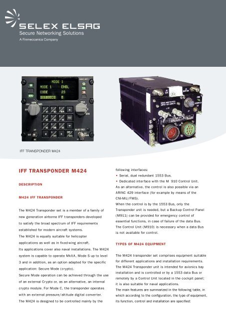
<strong>IFF</strong> <strong>TRANSPONDER</strong> <strong>M424</strong><br />
DESCRIPTION<br />
<strong>M424</strong> <strong>IFF</strong> <strong>TRANSPONDER</strong><br />
The <strong>M424</strong> Transponder set is a member of a family of<br />
new generation airborne <strong>IFF</strong> transponders developed<br />
to satisfy the broad spectrum of <strong>IFF</strong> requirements<br />
established for modern aircraft systems.<br />
The <strong>M424</strong> is equally suitable for helicopter<br />
applications as well as in fixed-wing aircraft.<br />
Its applications cover also naval installations. The <strong>M424</strong><br />
system is capable to operate MkXA, Mode S up to level<br />
3 and in addition, as an option adapted for the specific<br />
application: Secure Mode (crypto).<br />
Secure Mode operation can be achieved through the use<br />
of an external Crypto or, as an alternative, an internal<br />
crypto module. For Mode C, the transponder operates<br />
with an external pressure/altitude digital converter.<br />
The <strong>M424</strong> is designed to be controlled mainly by the<br />
following interfaces:<br />
• Serial, dual redundant 1553 Bus.<br />
• Dedicated interface with the M 910 Control Unit.<br />
As an alternative, the control is also possible via an<br />
ARINC 429 interface (for example by means of the<br />
CNI-MU/FMS).<br />
When the control is by the 1553 Bus, only the<br />
Transponder unit is needed, but a Backup Control Panel<br />
(M911) can be provided for emergency control of<br />
essential functions, in case of failure of the data Bus.<br />
The Control Unit (M910) is necessary when a data Bus<br />
is not available for control.<br />
TYPES OF <strong>M424</strong> EQUIPMENT<br />
The <strong>M424</strong> transponder set comprises equipment suitable<br />
for different applications and installation requirements.<br />
The <strong>M424</strong> Transponder unit is intended for avionics bay<br />
installation and is controlled or by a 1553 data Bus or<br />
remotely by a Control Unit located in the cockpit panel;<br />
it is also suitable for naval applications.<br />
The main features are summarized in the following table, in<br />
which according to the configuration, the type of equipment,<br />
its function, control and installation are specified:
System Type Function Intended Control Control Unit<br />
Configuration installation means required<br />
1- Data Bus <strong>M424</strong> Transponder Avionics bay MIL-STD-1553B No<br />
data Bus<br />
M911 Optional Cockpit Front panel N.A.<br />
Back up control Unit<br />
for emergency<br />
operation<br />
2- Control Unit <strong>M424</strong> Transponder Avionics bay Control Unit M910<br />
OPERATION<br />
M910 Control Unit Cockpit Front panel N.A.<br />
The <strong>M424</strong> <strong>IFF</strong> Transponder receives coded RF signals<br />
from interrogators, decodes these signals and generates<br />
coded RF replies. The <strong>M424</strong> operates, iaw Stanag 4193,<br />
in Modes MkXA and Mode S, i.e.:<br />
• Modes 1, 2, 3/A and C (Stanag 4193 MkXA, Part I<br />
and II)<br />
• Mode S up to Level 3 (Stanag 4193 Part IV and ICAO<br />
Annex 10)<br />
and in addition, as an option adapted for the specific<br />
application:<br />
Secure Mode (crypto)<br />
Secure Mode operation can be achieved through the use<br />
of an external Crypto or, as an alternative, an internal<br />
crypto module.<br />
CONTROL<br />
The flexibility of the Transponder allows a wide range of<br />
operations and alternative solutions.<br />
M910 CONTROL PANEL<br />
• Provides full control of transponder operation<br />
• Friendly display and keyboard design for system<br />
initialization in pre-flight<br />
• Conventional controls for recurrent in-flight operations<br />
• Display of equipment status<br />
• APX 100 compatible size<br />
• Display<br />
- NVG compatible lighting scheme i.a.w.<br />
MIL-L-85762A, Type 1A<br />
- Compatible with centralized background dimming<br />
- Ambient Light Sensor<br />
BACKUP EMERGENCY OPERATION<br />
In the DataBus configuration, by means of the BCP.<br />
DIVERSITY<br />
The Transponder must be connected to a dual omnidirectional<br />
antenna system to provide a full coverage above and<br />
below the aircraft plane; in this case the Transponder<br />
<strong>M424</strong> performs the diversity operation in accordance<br />
with STANAG 4193.<br />
ALTIMETER<br />
The <strong>M424</strong> provides wide flexibility for the Altimeter<br />
interface, since, in addition to the MIL1553, it<br />
incorporates a discrete (Gillham) interface and an<br />
additional serial A429 interface.<br />
TIME OF DAY<br />
The Transponder provides wide flexibility for the Time<br />
of Day (ToD) interface, needed for certain applications,<br />
since, in addition to the MIL 1553, it incorporates a<br />
serial PTTI (GPS) interface and a serial A429 interface.<br />
NAV DATA<br />
The Transponder supports multiple standards, as input<br />
interfaces, i.e. 1553 Bus, NMEA and A429.<br />
CRYPTO VARIABLES FILL CONNECTOR<br />
The Transponder is provided with a standard Fill<br />
connector for Secure Mode supporting two selectable<br />
standards:<br />
• DS 101<br />
• DS 102<br />
TCAS AND MODE S<br />
The <strong>M424</strong> incorporates two bi-directional A429<br />
interfaces, one to support the on-board TCAS function<br />
(iaw A735A) and another dedicated interface for the<br />
exchange of Full Level 2 or Level 3 Mode S data (function<br />
provided by an external ADLP function)<br />
Mode S operation:<br />
Level 2 basic surveillance, as defined in Stanag 4193<br />
Part IV, para. 5.1.1<br />
Full Level 2 and Level 3, in accordance with Stanag<br />
4193 Part IV and ICAO Annex 10; it will need the<br />
implementation of the specific interface with the<br />
aircraft for the exchange of data and controls (via the<br />
1553 DataBus or the A429 bi-directional interface).<br />
DISCRETE CONTROLS AND INDICATIONS<br />
The <strong>M424</strong> provides the necessary discrete interfaces<br />
with the platform for the <strong>IFF</strong> functions, controls and<br />
indications that are needed. Additional discrete<br />
interfaces are provided in the equipment to allow, for the<br />
MIL 1553 Bus configuration, redundant controls by<br />
means of the Backup Control Panel (BCP).<br />
DESIGN AND CONSTRUCTION<br />
The <strong>M424</strong> is a fully solid state equipment;<br />
it makes extensive use of large scale programmable<br />
components and state of art technologies, in order to<br />
reduce volume and weight maximising the reliability.<br />
Its structure is modular and includes a powerful BITE<br />
(Power-up, Continuous and Initiated BIT).
COOLING<br />
The Transponder Unit, the BCP and the Control Unit do<br />
not require forced air and do not include ventilators for<br />
cooling.<br />
SOFTWARE<br />
The <strong>M424</strong> is designed according to a flexible software<br />
architecture.<br />
The loading of updates can be accomplished via a<br />
standard serial interface (part of the Support Port).<br />
GROWTH POTENTIAL AND VARIANTS:<br />
Options: Extended Squitter (for ADS-B operation), ACC<br />
Growth: User defined Secure Mode.<br />
POWER SUPPLY<br />
The power supply accepts 28 V DC and provides DC<br />
voltages to operate the transponder.<br />
28 V DC is i.a.w. MIL-STD-704D;<br />
maximum input power is 60 W.<br />
MAIN FEATURES<br />
28 VDC or 115 Vac (if provided for routing out),<br />
switched out for an external Crypto.<br />
M910 CONTROL UNIT<br />
POWER SUPPLY<br />
The power supply accepts 28 V DC and provides DC voltages<br />
to operate the control Unit.<br />
28 V DC is i.a.w. MIL-STD-704D; maximum input power is<br />
30 W.<br />
28 V DC Panel Light for front panel illumination.<br />
5 V AC Panel Light also available for front panel<br />
illumination.<br />
M911 BACKUP CONTROL PANEL<br />
Provides reversionary control of the transponder in case<br />
of failure of the DataBus<br />
POWER SUPPLY<br />
5V DC Panel Light for front panel illumination.<br />
5 V DC Lamp Power.<br />
• <strong>M424</strong>, transponder system of new generation design, satisfies the broad spectrum of <strong>IFF</strong> requirements<br />
established for modern aircraft systems<br />
• STANAG 4193 MkXA transponder, including Mode S up to Level 3<br />
• Secure Mode capability<br />
• Crypto for Secure Mode operation can be an external unit or embedded crypto (internal module)<br />
• Diversity operation for spherical coverage<br />
• Alternative solutions of control interface (databus, control Unit)<br />
• Interface flexibility accommodates different installation requirements<br />
• Integration capability with TCAS II equipment provided via a dedicated interface<br />
• 1800 hours specified MTBF at 40°C AUF, more than 2000 achieved<br />
• Comprehensive Built-in test (PBIT, CBIT, IBIT)<br />
• Loading capability of software updates<br />
• Extended Squitter and ACC available
TECHNICAL SPECIFICATIONS<br />
M 424 Transponder<br />
Environmental conditions MIL-STD-810 E<br />
Operating temperature -40°C to +71°C<br />
Electromagnetic compatibility MIL-STD-461E<br />
Rx frequency 1030 ±0.5 MHz<br />
Sensitivity MkXA and Secure Mode: from –72 to –78 dBm<br />
Mode S: from –73 to –79 dBm<br />
Skirt bandwidth (selectivity) ±12 MHz at -40 dB<br />
±25 MHz at -60 dB<br />
Dynamic range from MTL to –22 dBm<br />
Tx frequency 1090 MHz<br />
Frequency stability ±0.1 MHz<br />
Output power from 25 dBW to 29 dBW<br />
1 dB max peak power variation between the pulses in the reply<br />
Reliability MTBF > 1800 hours at 40°C AUF<br />
Maintainability & Testability MTTR: < 10 min (LRU) and 40 min (SRU)<br />
Dimensions 136 x 136.5 x 219.3 mm (W x H x D)<br />
Weight 6.0 kg (6.5 kg when an embedded cryptomodule is included)<br />
Input power 28 V DC, 60 W<br />
M 910 Control Unit<br />
Environmental conditions MIL-STD-810 E “Panel mounted in cockpit console”<br />
Operating temperature -40°C to +71°C<br />
Electromagnetic compatibility MIL-STD-461E<br />
NVG MIL-L-85762A, Type 1, Class A<br />
HMI Alphanumeric display and keyboard, menu driven operation<br />
Reliability MTBF > 8000 hours at 40°C AIF<br />
Maintainability & Testability SRU MTTR < 30 min<br />
Dimensions 146 x 133.4 x 42.3 mm (W x H x D)<br />
Weight 2.0 kg<br />
Input power 28 V DC, 30 W<br />
M 911 Backup Control Panel<br />
Environmental conditions MIL-STD-810 E “Panel mounted in cockpit console”<br />
Operating temperature -40°C to +71°C<br />
Electromagnetic compatibility MIL-STD-461E<br />
NVG MIL-L-85762A, Type 1, Class A<br />
Reliability MTBF > 20000 hours at 40°C AIF<br />
Maintainability & Testability SRU MTTR < 30 min<br />
Dimensions 146 x 47 x 42.3 mm (W x H x D)<br />
Weight 0,5 kg<br />
Input power 5 VDC, (28 VDC available)<br />
<strong>SELEX</strong> <strong>Elsag</strong> S.p.A.<br />
Sales Department - Point of Contact: getinfo@selexelsag.com - www.selexelsag.com<br />
This publication is issued to provide outline information only which (unless agreed by <strong>SELEX</strong><br />
<strong>Elsag</strong> S.p.A. in writing) may not be used, applied or reproduced for any purpose or<br />
form part of any order or contract or be regarded as a representation relating to the<br />
products or services concerned. <strong>SELEX</strong> <strong>Elsag</strong> S.p.A. reserves the right to alter<br />
without notice the specification, design or conditions of supply of any product or service.<br />
© <strong>SELEX</strong> <strong>Elsag</strong> S.p.A. All Rights reserved<br />
CODE: e-A-SC-024 /V1/11/Z