Imaging Radar - Telephonics Corporation
Imaging Radar - Telephonics Corporation
Imaging Radar - Telephonics Corporation

You also want an ePaper? Increase the reach of your titles
YUMPU automatically turns print PDFs into web optimized ePapers that Google loves.
AN/APS-143G(V)1<br />
allows for switching between<br />
the two antennas in a scanto-scan<br />
interleaved fashion<br />
or a sector-interleaved fashion<br />
within a single 360°<br />
scan. This capability facilitates<br />
simultaneous, dual<br />
mode operation on either a<br />
scan-interleaved basis or by<br />
switching between the two<br />
antennas within a single<br />
360° scan. Performance in<br />
high-resolution maritime<br />
modes is also enhanced by<br />
illuminating the same target<br />
sector with both antennas<br />
within a single 360° scan.<br />
The primary antenna has a<br />
pencil beam, three-phasecenter,<br />
flat plate radiator<br />
with HH polarization. The<br />
secondary antenna is also<br />
pencil beam with VV polarization.<br />
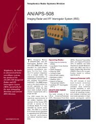
Antenna/Pedestal<br />
Microwave Front End<br />
(MFE)<br />
The MFE architecture<br />
simplifies the waveguide<br />
installation and minimizes<br />
RF losses prior to the LNAs.<br />
MFE functions include low<br />
noise amplification, preselection,<br />
receiver protection,<br />
duplexing function with<br />
receive path switching and<br />
transmit power monitoring.<br />
Included in the MFE is an<br />
optical delay line for automatic<br />
self calibration of the<br />
transmit/receive path.<br />
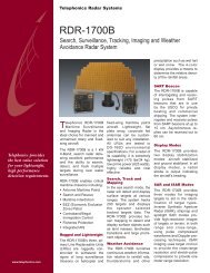
Microwave Front End<br />
Receiver/Transmitter<br />
(R/T)<br />
The transmitter uses an<br />
8kw TWT with 5% duty cycle<br />
for an average power output<br />
of 400 watts. The 1 GHz<br />
bandwidth provides extremely<br />
fine resolution and<br />
frequency agility. The threechannel<br />
receiver provides<br />
for both analog and digital<br />
pulse compression, depending<br />
on mode.<br />
• Production of multiple,<br />
high-resolution ISAR or<br />
Landspot images in a<br />
single pass of the<br />
aircraft<br />
• Production of very wide<br />
swath imagery in the<br />
Stripmap mode in real time<br />
• Integrated record/playback<br />
capability of time<br />
correlated raw sensor<br />
data, NAV data and<br />
control.<br />
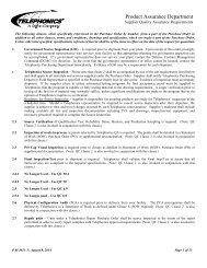
Receiver/Transmitter Signal Processor<br />
Signal Processor (SP)<br />
The SP is based on the<br />
Mercury Computer Raceway<br />
open architecture for highspeed<br />
data transfers. It is an<br />
air-cooled, 17-slot, 6U VME<br />
chassis. Features of this<br />
high throughput SP include:<br />
• High-speed, FPGA-based<br />
signal processing for<br />
automatic detection and<br />
tracking of low radar<br />
cross section targets in<br />
open ocean and littoral<br />
environments<br />
• Simultaneous Doppler<br />
Beam Sharpened <strong>Imaging</strong><br />
or Target Detection/TWS<br />
processing in the GMTI<br />
modes<br />
• Simultaneous Wide-Area<br />
Search (WAS) with Nav<br />
and Weather<br />
• Simultaneous NAV and<br />
Weather<br />
• SART or A-Scan Interleaved<br />
with WAS or Low<br />
RCS Search<br />
• Simultaneous WX and<br />
NAV mode processing<br />
display together with<br />
WAS mode<br />
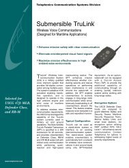
Inertial Measurement<br />
Unit (IMU)<br />
The IMU is the heart of the<br />
motion compensation subsystem.<br />
It is mounted adjacent<br />
to the antenna pedestal<br />
and enables precise measurement<br />
of the motion of<br />
the antenna phase centers<br />
relative to the aircraft flight<br />
path to ensure well-focused,<br />
high-resolution imagery at<br />
long ranges.<br />
Inertial Measurement Unit<br />
<strong>Radar</strong> Digital Data<br />
Recorder (RDDR)<br />
The RDDR is a commercial<br />
RAID data recorder.<br />
<strong>Radar</strong> Digital Data Recorder<br />
System Features of<br />
the AN/APS-143G(V)1<br />
• Wide Area Surveillance<br />
Mode (WAS). Provides<br />
maritime surveillance of<br />
medium to large RCS targets<br />
out to 200nm while<br />
operating at altitudes up to<br />
35,000 ft.<br />
• Low <strong>Radar</strong> Cross<br />
Section Mode (LRCS).<br />
Performs automatic detection<br />
of small (1m 2 ) to<br />
medium RCS targets out<br />
to 45 nm from typical altitudes<br />
of 500 ft. to 2000 ft.<br />
Two LRCS submodes are<br />
available, one optimized<br />
for periscope detection<br />
and another for search and<br />
rescue situations. Both<br />
LRCS sub-modes feature<br />
high-speed LRCS target<br />
detection in high sea<br />
states.<br />
• Maritime Tracking. Automatic<br />
target detection and<br />
track initiation is provided<br />
in both WAS and LRCS<br />
modes for up to 300 detected<br />
targets. Track filters<br />
(range and speed) suppress<br />
reporting of tracks<br />
that are not of interest to<br />
the operator. Landmass<br />
rejection, based on a<br />
stored world map database,<br />
inhibits auto initiation<br />
of any tracks located<br />
over land.<br />
• Classification Capabilities<br />
A-Scan Mode. Displays<br />
the designated target’s<br />
intensity vs. range.<br />
A-Scan is concurrent<br />
with WAS and LRCS<br />
modes.<br />
Seaspot (ISAR) Mode.<br />
Seaspot relies on target<br />
ship motion (Doppler) to<br />
focus images of targets<br />
under a broad range of<br />
sea states at long standoff<br />
ranges. Image resolutions<br />
of less than one<br />
meter are available.