Imaging Radar - Telephonics Corporation
Imaging Radar - Telephonics Corporation
Imaging Radar - Telephonics Corporation

Create successful ePaper yourself
Turn your PDF publications into a flip-book with our unique Google optimized e-Paper software.
<strong>Telephonics</strong>, the leader<br />
in advanced airborne<br />
surveillance systems,<br />
has produced the<br />
AN/APS-143G(V)1<br />
Integrated <strong>Radar</strong> and<br />
IFF Interrogator System<br />
(IRIS) specifically for<br />
the most demanding<br />
Maritime and Littoral<br />
MPA Missions.<br />
www.telephonics.com<br />
<strong>Telephonics</strong> <strong>Radar</strong> Systems<br />
AN/APS-143G(V)1<br />
<strong>Imaging</strong> <strong>Radar</strong> and IFF Interrogator System (IRIS)<br />
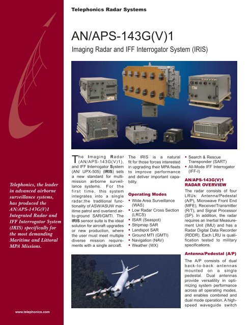
The I maging R adar<br />
(AN/APS-143G(V)1),<br />
and IFF Interrogator System<br />
(AN/ UPX-505) (IRIS) sets<br />
a new standard for multimission<br />
airborne surveillance<br />
systems. For the<br />
first time, this system<br />
integrates into a single<br />
radar,the traditional functionality<br />
of ASW/ASUW maritime<br />
patrol and overland airto-ground<br />
SAR/GMTI. The<br />
IRIS sensor suite is the ideal<br />
solution for aircraft upgrades<br />
or new production, where<br />
the user must meet multiple<br />
diverse mission requirements<br />
with a single aircraft.<br />
The IRIS is a natural<br />
fit for those forces interested<br />
in upgrading their MPA fleets<br />
to improve performance<br />
and deliver important capability.<br />
Operating Modes<br />
• Wide Area Surveillance<br />
(WAS)<br />
• Low <strong>Radar</strong> Cross Section<br />
(LRCS)<br />
• ISAR (Seaspot)<br />
• Stripmap SAR<br />
• Landspot SAR<br />
• Ground MTI (GMTI)<br />
• Navigation (NAV)<br />
• Weather (WX)<br />
• Search & Rescue<br />
Transponder (SART)<br />
• All-Mode IFF Interrogator<br />
(IFF-I)<br />
AN/APS-143G(V)1<br />
RADAR OVERVIEW<br />
The radar consists of four<br />
LRUs: Antenna/Pedestal<br />
(A/P), Microwave Front End<br />
(MFE), Receiver/Transmitter<br />
(R/T), and Signal Processor<br />
(SP). In addition, the radar<br />
requires an Inertial Measurement<br />
Unit (IMU) and has a<br />
<strong>Radar</strong> Digital Data Recorder<br />
(RDDR). Each LRU is qualification<br />
tested to military<br />
specifications.<br />
Antenna/Pedestal (A/P)<br />
The A/P consists of dual<br />
back-to-back antennas<br />
mounted on a single<br />
pedestal. Dual antennas<br />
provide versatility in optimizing<br />
system performance<br />
across all operating modes,<br />
and enables combined and<br />
dual mode operation. A highspeed<br />
waveguide switch
AN/APS-143G(V)1<br />
allows for switching between<br />
the two antennas in a scanto-scan<br />
interleaved fashion<br />
or a sector-interleaved fashion<br />
within a single 360°<br />
scan. This capability facilitates<br />
simultaneous, dual<br />
mode operation on either a<br />
scan-interleaved basis or by<br />
switching between the two<br />
antennas within a single<br />
360° scan. Performance in<br />
high-resolution maritime<br />
modes is also enhanced by<br />
illuminating the same target<br />
sector with both antennas<br />
within a single 360° scan.<br />
The primary antenna has a<br />
pencil beam, three-phasecenter,<br />
flat plate radiator<br />
with HH polarization. The<br />
secondary antenna is also<br />
pencil beam with VV polarization.<br />
Antenna/Pedestal<br />
Microwave Front End<br />
(MFE)<br />
The MFE architecture<br />
simplifies the waveguide<br />
installation and minimizes<br />
RF losses prior to the LNAs.<br />
MFE functions include low<br />
noise amplification, preselection,<br />
receiver protection,<br />
duplexing function with<br />
receive path switching and<br />
transmit power monitoring.<br />
Included in the MFE is an<br />
optical delay line for automatic<br />
self calibration of the<br />
transmit/receive path.<br />
Microwave Front End<br />
Receiver/Transmitter<br />
(R/T)<br />
The transmitter uses an<br />
8kw TWT with 5% duty cycle<br />
for an average power output<br />
of 400 watts. The 1 GHz<br />
bandwidth provides extremely<br />
fine resolution and<br />
frequency agility. The threechannel<br />
receiver provides<br />
for both analog and digital<br />
pulse compression, depending<br />
on mode.<br />
• Production of multiple,<br />
high-resolution ISAR or<br />
Landspot images in a<br />
single pass of the<br />
aircraft<br />
• Production of very wide<br />
swath imagery in the<br />
Stripmap mode in real time<br />
• Integrated record/playback<br />
capability of time<br />
correlated raw sensor<br />
data, NAV data and<br />
control.<br />
Receiver/Transmitter Signal Processor<br />
Signal Processor (SP)<br />
The SP is based on the<br />
Mercury Computer Raceway<br />
open architecture for highspeed<br />
data transfers. It is an<br />
air-cooled, 17-slot, 6U VME<br />
chassis. Features of this<br />
high throughput SP include:<br />
• High-speed, FPGA-based<br />
signal processing for<br />
automatic detection and<br />
tracking of low radar<br />
cross section targets in<br />
open ocean and littoral<br />
environments<br />
• Simultaneous Doppler<br />
Beam Sharpened <strong>Imaging</strong><br />
or Target Detection/TWS<br />
processing in the GMTI<br />
modes<br />
• Simultaneous Wide-Area<br />
Search (WAS) with Nav<br />
and Weather<br />
• Simultaneous NAV and<br />
Weather<br />
• SART or A-Scan Interleaved<br />
with WAS or Low<br />
RCS Search<br />
• Simultaneous WX and<br />
NAV mode processing<br />
display together with<br />
WAS mode<br />
Inertial Measurement<br />
Unit (IMU)<br />
The IMU is the heart of the<br />
motion compensation subsystem.<br />
It is mounted adjacent<br />
to the antenna pedestal<br />
and enables precise measurement<br />
of the motion of<br />
the antenna phase centers<br />
relative to the aircraft flight<br />
path to ensure well-focused,<br />
high-resolution imagery at<br />
long ranges.<br />
Inertial Measurement Unit<br />
<strong>Radar</strong> Digital Data<br />
Recorder (RDDR)<br />
The RDDR is a commercial<br />
RAID data recorder.<br />
<strong>Radar</strong> Digital Data Recorder<br />
System Features of<br />
the AN/APS-143G(V)1<br />
• Wide Area Surveillance<br />
Mode (WAS). Provides<br />
maritime surveillance of<br />
medium to large RCS targets<br />
out to 200nm while<br />
operating at altitudes up to<br />
35,000 ft.<br />
• Low <strong>Radar</strong> Cross<br />
Section Mode (LRCS).<br />
Performs automatic detection<br />
of small (1m 2 ) to<br />
medium RCS targets out<br />
to 45 nm from typical altitudes<br />
of 500 ft. to 2000 ft.<br />
Two LRCS submodes are<br />
available, one optimized<br />
for periscope detection<br />
and another for search and<br />
rescue situations. Both<br />
LRCS sub-modes feature<br />
high-speed LRCS target<br />
detection in high sea<br />
states.<br />
• Maritime Tracking. Automatic<br />
target detection and<br />
track initiation is provided<br />
in both WAS and LRCS<br />
modes for up to 300 detected<br />
targets. Track filters<br />
(range and speed) suppress<br />
reporting of tracks<br />
that are not of interest to<br />
the operator. Landmass<br />
rejection, based on a<br />
stored world map database,<br />
inhibits auto initiation<br />
of any tracks located<br />
over land.<br />
• Classification Capabilities<br />
A-Scan Mode. Displays<br />
the designated target’s<br />
intensity vs. range.<br />
A-Scan is concurrent<br />
with WAS and LRCS<br />
modes.<br />
Seaspot (ISAR) Mode.<br />
Seaspot relies on target<br />
ship motion (Doppler) to<br />
focus images of targets<br />
under a broad range of<br />
sea states at long standoff<br />
ranges. Image resolutions<br />
of less than one<br />
meter are available.
Seaspot (ISAR) Mode<br />
• Target Classification<br />
Software (TCS). Contains<br />
mensuration tools<br />
to assist the operator<br />
in measuring the length<br />
of the target, relative<br />
location and size of the<br />
dominant scatterers from<br />
either the A-Scan profile<br />
or the Seaspot image.<br />
• Land <strong>Imaging</strong> Modes<br />
Stripmap. Produces a<br />
continuous streaming<br />
SAR image of the terrain<br />
offset from the side of<br />
the aircraft. The image<br />
can be along a track parallel<br />
to the aircraft flight<br />
path or at an angle relative<br />
to the flight path.<br />
Resolutions below one<br />
meter are available in all<br />
SAR modes.<br />
Landspot. While in<br />
Stripmap mode, the<br />
operator can switch to<br />
Landspot Mode for higher<br />
resolution imaging of a<br />
selected target area in a<br />
single pass of the aircraft.<br />
Multiple Landspot<br />
images can be<br />
produced during a single<br />
pass of the aircraft.<br />
• Ground Moving Target<br />
Indicator (GMTI). Provides<br />
the capability to<br />
detect and track targets<br />
moving against ground<br />
clutter. Target positions<br />
and track are overlaid<br />
on a Doppler Beam<br />
Sharpened (DBS) image<br />
generated simultaneously<br />
with the GMTI data, or a<br />
map pre-loaded into the<br />
operator workstation.<br />
• Navigation Mode (NAV).<br />
Performs real-beam coastline<br />
and surface mapping.<br />
A combined WAS/NAV<br />
mode is provided and<br />
typically the NAV mode<br />
display is routed to a<br />
cockpit display and the<br />
WAS mode imagery to<br />
the radar workstation.<br />
Wide Area Surveillance Mode<br />
Land <strong>Imaging</strong> Mode Stripmap<br />
• Weather Mode (WX). Provides<br />
four-color weather<br />
presentation based on<br />
Rain-fall reflectivity measurements<br />
out to 200 nm.<br />
A combined WAS/WX<br />
mode is provided with the<br />
WX mode display routed<br />
to the cockpit and the<br />
WAS imagery routed to<br />
the radar workstation.<br />
Ground Moving Target Indicator (GMTI)<br />
AN/UPX-505<br />
IFF Interrogator<br />
(IFF-I)<br />
The AN/UPX-505 IFF<br />
Interrogator (IFF-I) equipment<br />
is an integral part<br />
of the AN/APS-143G(V)1<br />
multi-mode radar. The unique<br />
design of the IFF<br />
required for multi-mode<br />
radars enables this sensor<br />
to provide IFF reply video<br />
and target reports in all<br />
radar modes, if commanded,<br />
or independently in<br />
<strong>Radar</strong> Standby. The equipment<br />
is a Mark XIIA<br />
Interrogator with Mode S.<br />
Operation in Modes 1, 2, 3,<br />
C, 4, 5 Level 1 and Level 2,<br />
and Mode S Level 1 and<br />
Level 2, is provided in such<br />
a way as to maximize<br />
automation and transaction<br />
management to ease<br />
operator workload. (Military<br />
modes are export controlled).<br />
In the IRIS, the IFF<br />
antenna shares a common<br />
aperture with the radar and<br />
is linked to the particular<br />
radar mode functionality<br />
thus providing exceptional<br />
performance. The difficult<br />
task of correlating IFF and<br />
radar data, normally part<br />
of the Integrated Mission<br />
system software, is accomplished<br />
within the IRIS. This<br />
approach, of a single integrated<br />
radar and IFF,<br />
eliminates the cost and risks<br />
associated with procuring<br />
separate radar and IFF<br />
interrogator sensors.<br />
IFF Interrogator
For further information contact:<br />
<strong>Telephonics</strong> <strong>Corporation</strong><br />
815 Broad Hollow Road<br />
Farmingdale, NY 11735-3904<br />
(631) 755-7000<br />
Fax (631) 755-7200<br />
www.telephonics.com<br />
©2012 <strong>Telephonics</strong> 34174C<br />
AN/APS-143G(V)1<br />
System Specifications<br />
AN/APS-143G(V)1 Physical Characteristics<br />
WRA Name<br />
Antenna Pedestal<br />
LN-251 (A/P)<br />
Receiver/Transmitter<br />
(R/T)<br />
Signal Processor<br />
(SP)<br />
Microwave Front End<br />
(MFE)<br />
Total System Weight<br />
Environment<br />
Operating Temperature<br />
Humidity<br />
Altitude<br />
Operating Vibration<br />
Functional Shock<br />
Crash Safety<br />
EMI/EMC<br />
Power<br />
System Interfaces<br />
Wt.<br />
(Lbs.)<br />
106<br />
13<br />
90<br />
79<br />
46<br />
334<br />
Specifications subject to change without prior notice.<br />
Dimensions<br />
(inches)<br />
L<br />
46.0<br />
W<br />
46.00<br />
23.6 15.35 9.9<br />
23.1 15.35 11.8<br />
20.3 15.00 7.3<br />
Radome Mounted<br />
Equipment<br />
-55 to +55°C<br />
95%<br />
35,000 ft.<br />
0.1g 2 /Hz<br />
6g<br />
15g<br />
MIL-STD-461D<br />
MIL-STD-461A<br />
AN/APS-143G(V)1 Interfaces Requirements<br />
• 115/208 VAC, 400 Hz – 3-phase, 3500 VA<br />
• Weight on Wheels Switch<br />
• 1553 Bus – Platform NAV Data and Control<br />
• Dual Operator RGB Video<br />
• Ethernet – Track Data & A-Scan<br />
• Gigabit Ethernet – Image Exploitation<br />
• ESM Blanking<br />
• Dry Air<br />
Logistics<br />
• Comprehensive BIT<br />
• > 900 Hr. MTBF (AIC)<br />
• < 25 Min. MTTR<br />
H Type Consumption<br />
39.1<br />
Powered<br />
from MFE<br />
115 Vac.<br />
3�, 400 Hz<br />
115 Vac.<br />
3�, 400 Hz<br />
115 Vac.<br />
3�, 400 Hz<br />
Power<br />
– 500<br />
5.3 Amps<br />
2.3 Amps<br />
1.8 Amps<br />
Cabin Mounted<br />
Equipment<br />
-25 to +55°C<br />
95%<br />
15,000 ft.<br />
0.1g 2 /Hz (SP @ 0.3g 2 /Hz)<br />
6g<br />
30g<br />
MIL-STD-461D<br />
MIL-STD-461A<br />
Heat<br />
Diss.<br />
Watts<br />
1300<br />
760<br />
105