NetSure 701 Application Guide - Emerson Network Power
NetSure 701 Application Guide - Emerson Network Power
NetSure 701 Application Guide - Emerson Network Power

You also want an ePaper? Increase the reach of your titles
YUMPU automatically turns print PDFs into web optimized ePapers that Google loves.
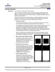
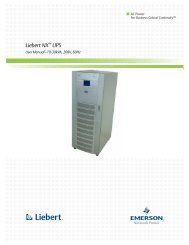
SYSTEM OVERVIEW<br />
Description: -48VDC @ up to 4000 amperes <strong>Power</strong> System.<br />
Page 1 of 141<br />
SAG582126000<br />
System <strong>Application</strong> <strong>Guide</strong><br />
Spec. No. 582126000 (Model <strong>701</strong>NVBB)<br />
Issue AR, July 13, 2011<br />
Home<br />
This power system is designed to power a load while charging a positive grounded<br />
battery. This system is capable of operating in a batteryless installation or off battery for<br />
maintenance purposes. The system is designed for operation with the positive output<br />
grounded.<br />
The NETSURE <strong>701</strong>NVBB DC <strong>Power</strong> System is a complete integrated power system<br />
containing rectifiers (PCUs), intelligent control, metering, monitoring, and distribution.<br />
This power system consists of the following components.<br />
� Distribution Cabinet<br />
The system always includes a minimum of one Distribution Cabinet, which provides<br />
DC distribution through fuses and/or circuit breakers.<br />
Four different sizes of Distribution Cabinets may be ordered to accept from one (1) to<br />
four (4) Distribution Bus Modules. A variety of Distribution Bus Modules are available<br />
that provide combinations of load distribution, battery distribution, low voltage load or<br />
battery disconnect, and manual battery disconnect. The Distribution Cabinet is<br />
factory mounted in the relay rack specified when ordered.<br />
Most of the Distribution Bus Modules accept either TPS/TLS-type fuseholders or<br />
Bullet Nose-type circuit breakers. TPH-type fuses and GJ/218-type circuit breakers<br />
are also available in ratings up to 600 amps.<br />
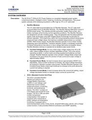
� Meter-Control-Alarm (MCA) Assembly<br />
The system contains one MCA. The MCA controls the operation of the Rectifier<br />
Modules (PCUs). The MCA also provides power<br />
system control, metering, monitoring, and alarm<br />
functions.<br />
� Rectifier Module (PCU)<br />
Mounting Shelves<br />
The system contains one or more Rectifier Module<br />
(PCU) Mounting Shelves, each of which houses up<br />
to six (6) Rectifier Modules (PCUs). Refer to<br />
PD588705000 for more information.<br />
� Rectifier Modules (PCUs)<br />
The system contains Rectifier Modules (PCUs),<br />
which provide load power, battery float current, and<br />
battery recharge current during normal operating<br />
conditions. Refer to PD588705000 for more<br />
information.<br />
� DC-DC Converter System<br />
Where +24VDC load power is required, DC-DC<br />
Converters are available in this power system.<br />
� Monitoring System<br />
An LMS1000 Monitoring System may also be furnished. Refer to SAG586505500 for<br />
more information.<br />
This document is property of <strong>Emerson</strong> <strong>Network</strong> <strong>Power</strong>, Energy Systems, North America, Inc. and contains confidential and proprietary information owned by <strong>Emerson</strong> <strong>Network</strong> <strong>Power</strong>, Energy<br />
Systems, North America, Inc. Any copying, use, or disclosure of it without the written permission of <strong>Emerson</strong> <strong>Network</strong> <strong>Power</strong>, Energy Systems, North America, Inc. is strictly prohibited.
SAG582126000 System <strong>Application</strong> <strong>Guide</strong><br />
Issue AR, July 13, 2011 Spec. No. 582126000 (Model <strong>701</strong>NVBB)<br />
Family: NETSURE<br />
Spec. No.: 582126000<br />
Model: <strong>701</strong>NVBB<br />
Output Voltage: -48 Volts DC<br />
Rectifier System Input Voltage Nominal 208/240 volts AC, single phase, 50/60 Hz, with an operating<br />
range of 176 to 264 volts. Acceptable input frequency range is 45 to 65<br />
Hz.<br />
Output Capacity:<br />
System: 4000 Amperes, maximum<br />
Bay: 2000 Amperes, maximum (1500A maximum when equipped with List<br />
AH; 1200A maximum when equipped with List RA or RB)<br />
Distribution Bus Module: 500 Amperes, maximum (List ND rated for 960A)<br />
Rectifier Module (PCU)<br />
1R483200 and 1R483200e: 55.2A @ -58VDC to 66.6A @ -48VDC<br />
Rectifier Module (PCU)<br />
1R483500e: 60.3A @ -58VDC to 72.9A @ -48VDC<br />
Agency Approval: UL 1801 Listed (“c UL”), NEBS<br />
Framework Type: Relay Rack<br />
Mounting Width: 23 Inches, nominal<br />
Mounting Depth:<br />
Distribution Cabinet: 18 Inches (single-bay), 21 Inches (multi-bay)<br />
(List RC, RD, and RE adds 5.25 inches to back of system, see Overall<br />
Dimensions Illustrations)<br />
Rectifier Module<br />
Mounting Shelf: 18 Inches<br />
Battery Tray: 24.4 Inches<br />
Access: Front, Sides, and Rear for Installation and Maintenance,<br />
Front for Operation<br />
Supplemental Bay(s) Available: One<br />
Control: Microprocessor<br />
Color: Bay and Rectifier Module Faceplates: Textured Gray (Spec. M500-147)<br />
Rectifier Shelf and Rectifier Modules Bodies: Bright Zinc Plating (Spec.<br />
M500-53)<br />
Options: Main Bay, Supplemental Bay (located next to Main Bay), Supplemental<br />
Bay 'Distribution Only' Option, Supplemental Bay (located away from<br />
Main Bay), MCA (standard), MCA (special application), MCA (special<br />
application), MCA (special application), 1-Row Distribution Cabinet,<br />
2-Row Distribution Cabinet, 3-Row Distribution Cabinet, 4-Row<br />
Distribution Cabinet, Distribution Cabinet Top Shield, Rectifier Module<br />
Mounting Shelf Interface Components, Top Mount AC Input Termination<br />
Panel, Optional 20A Converter Module, Optional 160A Converter Shelf<br />
(Initial Shelf), Optional 160A Converter Shelf (Expansion Shelf), Audible<br />
Alarm and Alarm Termination Card, MCA Interface Modem Option, MCA<br />
Interface WinLink Software, MCA Interface Combination Modem/RS-232<br />
Page 2 of 141<br />
Home<br />
This document is property of <strong>Emerson</strong> <strong>Network</strong> <strong>Power</strong>, Energy Systems, North America, Inc. and contains confidential and proprietary information owned by <strong>Emerson</strong> <strong>Network</strong> <strong>Power</strong>, Energy<br />
Systems, North America, Inc. Any copying, use, or disclosure of it without the written permission of <strong>Emerson</strong> <strong>Network</strong> <strong>Power</strong>, Energy Systems, North America, Inc. is strictly prohibited.
System <strong>Application</strong> <strong>Guide</strong> SAG582126000<br />
Spec. No. 582126000 (Model <strong>701</strong>NVBB) Issue AR, July 13, 2011<br />
Home<br />
Option, MCA Interface Ethernet Option (WinLink Compatible +<br />
Web Interface), MCA Interface Ethernet Option (WinLink<br />
Compatible + Web Interface + SNMP), MCA Interface Ethernet Option<br />
(WinLink Compatible + Web Interface + Battery Monitoring), MCA<br />
Interface Ethernet Option (WinLink Compatible + Web Interface + SNMP<br />
+ Battery Monitoring), Capacitor Pre-Charge Assembly, LMS1000<br />
Monitoring System, Battery Stand, Battery Tray (Pre-Cabled),<br />
Distribution Panels<br />
Accessories: High-Efficiency Rectifier Module, Rectifier Module, Relay Racks,<br />
Transition Plates, Distribution Devices, Wiring Components, Rectifier<br />
Module Mounting Position Blank Cover Panel, Battery Charge<br />
Temperature Compensation Probe for Single Probe Digital<br />
Compensation, Battery Charge Temperature Compensation Probe<br />
Concentrator for Multiple Probe Use (TXM), Adding Additional Shelf in<br />
Field Output Busbar Kit, Battery Busbar Extension Kit, Battery Busbar<br />
Extension Kit, Battery Landing Busbar Kit, Circuit Breaker Lug Adapter<br />
Busbar, Circuit Breaker Lug Adapter Busbar Kit, Circuit Breaker Lug<br />
Adapter Busbar Kit, Load Lug Hardware Kit, Load Lug Hardware Kit,<br />
LVD Contactor Bypass Kit, External Shunt Monitoring Kit, System Load<br />
Shunt Test Point Kit, Optional Front Battery Cover, Replacement Cables,<br />
Replacement Components<br />
Environment: -40°C to +40°C (-40°F to +104°F)<br />
Page 3 of 141<br />
This document is property of <strong>Emerson</strong> <strong>Network</strong> <strong>Power</strong>, Energy Systems, North America, Inc. and contains confidential and proprietary information owned by <strong>Emerson</strong> <strong>Network</strong> <strong>Power</strong>, Energy<br />
Systems, North America, Inc. Any copying, use, or disclosure of it without the written permission of <strong>Emerson</strong> <strong>Network</strong> <strong>Power</strong>, Energy Systems, North America, Inc. is strictly prohibited.
SAG582126000 System <strong>Application</strong> <strong>Guide</strong><br />
Issue AR, July 13, 2011 Spec. No. 582126000 (Model <strong>701</strong>NVBB)<br />
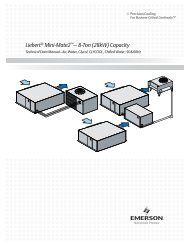
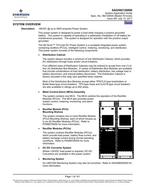
582126000<br />
List 45, 46: Top Mount AC<br />
Input Termination Panel<br />
Distribution Cabinet<br />
List 24 (4-Row)<br />
List 23 (3-Row)<br />
List 22 (2-Row)<br />
List 21 (1-Row)<br />
MCA<br />
List 10, 11, 12, 13<br />
LMS1000<br />
Monitoring System<br />
List 80<br />
Rectifier Module<br />
Mounting Shelf Components<br />
List 31<br />
Rectifier Module<br />
P/N 1R483200e or<br />
P/N 1R483200 or<br />
P/N 1R483500E<br />
See Also<br />
System Overview<br />
Table of Contents<br />
Ordering Information<br />
List Descriptions<br />
Specifications<br />
Physical Size Information<br />
Related Documentation<br />
Main Bay:……………………………………………...…List 1<br />
Supplemental Bay (located next to Main Bay):………List 2<br />
Supplemental Bay 'Distribution Only' Option:………...List 4<br />
Supplemental Bay (located away from Main Bay):.….List 5<br />
Distribution Bus<br />
Row D (Row 4)<br />
Distribution Bus<br />
Row C (Row 3)<br />
Distribution Bus<br />
Row B (Row 2)<br />
Distribution Bus<br />
Row A (Row 1)<br />
Page 4 of 141<br />
Home<br />
Distribution Assembly List AA, AB, AC,<br />
AD, AE, AG, AH, AJ, AK, AL, AM, AN,<br />
AP, BA, CA, CB, CD, CE, CF, CG, CJ,<br />
EA, GB, JA, JB, JC, JD, KA, LB, LC,<br />
NA, NB, NC, ND, TA, TB<br />
List RA: LV Battery Disconnect<br />
List RB, RC: Manual Battery<br />
Disconnect<br />
List RD: LV/Manual Battery<br />
Disconnect<br />
List RE: LV Battery Disconnect<br />
Other Options<br />
List 29: Distribution Cabinet Top Shield<br />
List 62: 20A Converter Module<br />
List 63, 64: 160A DC-DC Converter<br />
Shelves<br />
List 71: Optional Audible Alarm and<br />
Alarm Termination Circuit Card<br />
List 72: MCA Interface Modem Option<br />
List 73:MCA Interface WinLink<br />
Software<br />
List 74: MCA Interface Combination<br />
Modem/RS-232 Option<br />
List 75: MCA Interface Ethernet<br />
Option: WinLink Compatible + Web<br />
Interface<br />
List 76: MCA Interface Ethernet Option:<br />
WinLink Compatible + Web Interface +<br />
SNMP<br />
List 77: MCA Interface Ethernet Option:<br />
WinLink Compatible + Web Interface +<br />
Battery Monitoring<br />
List 78: MCA Interface Ethernet<br />
Option: WinLink Compatible + Web<br />
Interface + SNMP + Battery Monitoring<br />
List 79: Capacitor Precharge Assembly<br />
List 92: Battery System<br />
List 93: Battery Tray<br />
This document is property of <strong>Emerson</strong> <strong>Network</strong> <strong>Power</strong>, Energy Systems, North America, Inc. and contains confidential and proprietary information owned by <strong>Emerson</strong> <strong>Network</strong> <strong>Power</strong>, Energy<br />
Systems, North America, Inc. Any copying, use, or disclosure of it without the written permission of <strong>Emerson</strong> <strong>Network</strong> <strong>Power</strong>, Energy Systems, North America, Inc. is strictly prohibited.
System <strong>Application</strong> <strong>Guide</strong> SAG582126000<br />
Spec. No. 582126000 (Model <strong>701</strong>NVBB) Issue AR, July 13, 2011<br />
TABLE OF CONTENTS<br />
System<br />
Overview Picture<br />
Ordering Information<br />
List<br />
Descriptions<br />
Accessory<br />
Descriptions<br />
Page 5 of 141<br />
Specifications<br />
Physical Size<br />
Information<br />
Related<br />
Documentation<br />
SYSTEM OVERVIEW.................................................................................................................................................1<br />
TABLE OF CONTENTS.............................................................................................................................................5<br />
ORDERING INFORMATION......................................................................................................................................9<br />
List Options..........................................................................................................................................................9<br />
List Options (Numbers) ....................................................................................................................................9<br />
List Options (Letters) (Distribution Bus Modules) ..........................................................................................11<br />
Accessory Options............................................................................................................................................15<br />
LIST DESCRIPTIONS..............................................................................................................................................16<br />
List 1: Main Bay Common Equipment (<strong>Power</strong> and Distribution)...................................................................16<br />
List 2: Supplemental Bay Common Equipment (<strong>Power</strong> and Distribution) (located next to Main Bay) .........17<br />
List 4: “Distribution Only” Option for Lists 2 or 5 ...........................................................................................18<br />
List 5: Supplemental Bay Common Equipment (<strong>Power</strong> and Distribution) (located away from Main<br />
Bay) ................................................................................................................................................................18<br />
List 10: MCA (Standard <strong>Application</strong>).............................................................................................................19<br />
List 11: MCA (Special <strong>Application</strong>)................................................................................................................19<br />
List 12: MCA (Special <strong>Application</strong>)................................................................................................................19<br />
List 13: MCA (Special <strong>Application</strong>)................................................................................................................20<br />
List 21: One-Row Distribution Cabinet..........................................................................................................20<br />
List 22: Two-Row Distribution Cabinet..........................................................................................................21<br />
List 23: Three-Row Distribution Cabinet .......................................................................................................22<br />
List 24: Four-Row Distribution Cabinet .........................................................................................................22<br />
List 29: Top Shield for Distribution Cabinet...................................................................................................23<br />
List 31: Rectifier Module Mounting Shelf Interface Components..................................................................23<br />
List 45: Top Mount AC Input Termination Panel for Single Phase Input ......................................................23<br />
List 46: Top Mount AC Input Termination Panel for Three Phase Input.......................................................24<br />
List 62: Optional 20A Converter Module .......................................................................................................25<br />
List 63: Optional 160A Converter Shelf (Initial Shelf)....................................................................................25<br />
List 64: Optional 160A Converter Shelf (Expansion Shelf) ...........................................................................26<br />
List 71: Optional Audible Alarm and Alarm Termination Circuit Card...........................................................26<br />
List 72: MCA Interface Modem Option..........................................................................................................27<br />
List 73: MCA Interface WinLink Software .....................................................................................................27<br />
List 74: MCA Interface Combination Modem/RS-232 Option .......................................................................28<br />
List 75: MCA Interface Ethernet Option: WinLink Compatible + Web Interface ...........................................28<br />
List 76: MCA Interface Ethernet Option: WinLink Compatible + Web Interface + SNMP.............................29<br />
List 77: MCA Interface Ethernet Option: WinLink Compatible + Web Interface + Battery Monitoring..........29<br />
List 78: MCA Interface Ethernet Option: WinLink Compatible + Web Interface + SNMP + Battery<br />
Monitoring.......................................................................................................................................................30<br />
List 79: Capacitor Precharge Assembly........................................................................................................30<br />
List 80: LMS1000 Monitoring System ...........................................................................................................31<br />
List 92: Battery Stand Interface Components ...............................................................................................31<br />
List 93: Battery Tray, Pre-Cabled..................................................................................................................32<br />
List AA: Distribution Bus Module (P/N 509840) (24) Fuse/Circuit Breaker System Positions......................36<br />
List AB: Distribution Bus Module (P/N 428316100) (3) GJ/218 Circuit Breaker System Positions ..............37<br />
List AC: Distribution Bus Module (P/N 507198) (3) GJ/218 Circuit Breaker System Positions ....................38<br />
This document is property of <strong>Emerson</strong> <strong>Network</strong> <strong>Power</strong>, Energy Systems, North America, Inc. and contains confidential and proprietary information owned by <strong>Emerson</strong> <strong>Network</strong> <strong>Power</strong>, Energy<br />
Systems, North America, Inc. Any copying, use, or disclosure of it without the written permission of <strong>Emerson</strong> <strong>Network</strong> <strong>Power</strong>, Energy Systems, North America, Inc. is strictly prohibited.
SAG582126000 System <strong>Application</strong> <strong>Guide</strong><br />
Issue AR, July 13, 2011 Spec. No. 582126000 (Model <strong>701</strong>NVBB)<br />
List AD: Distribution Bus Module (P/N 509565) (8) GJ/218 Circuit Breaker System Positions<br />
(Upper Two Rows) .........................................................................................................................................39<br />
List AE: Distribution Bus Module (P/N 509648) (8) GJ/218 Circuit Breaker System Positions<br />
(Lower Two Rows) .........................................................................................................................................40<br />
List AG: Distribution Bus Module (P/N 514010) (2) TPH Fuse System Positions ........................................41<br />
List AH: Distribution Bus Module Ground Bar Assembly (P/N 500676) for Use with Up to (2) List<br />
AG, AJ, CG, or CJ; or (1) List AP...................................................................................................................42<br />
List AJ: Distribution Bus Module (P/N 520819) (2) TPH Fuse System Positions with Load Metering<br />
Shunts ............................................................................................................................................................43<br />
List AK: Distribution Bus Module (P/N 520805) (24) Fuse/Circuit Breaker System Positions......................44<br />
List AL: Distribution Bus Module Ground Bar Assembly for Use with Up to (2) List AK ...............................45<br />
List AM: Distribution Bus Module (P/N 524632) (20) Fuse/Circuit Breaker System Positions (1) 3-<br />
Pole Input Disconnect Fuse/Circuit Breaker Position ....................................................................................46<br />
List AN: Distribution Bus Module (P/N 541386) (24) Fuse/Circuit Breaker System Positions......................47<br />
List AP: Distribution Bus Module (P/N 541537) (4) TPH Fuse System Positions.........................................48<br />
List BA: Distribution Bus Module (P/N 520600) (12) Fuse/Circuit Breaker System Positions with<br />
LVD (8) Fuse/Circuit Breaker System Positions without LVD........................................................................49<br />
List CA: Distribution Bus Module (P/N 509846) (20) Fuse/Circuit Breaker System Positions<br />
w/LVLD...........................................................................................................................................................50<br />
List CB: Distribution Bus Module (P/N 509904) (3) GJ/218 Circuit Breaker System Positions<br />
w/LVLD...........................................................................................................................................................51<br />
List CD: Distribution Bus Module (P/N 507197) (3) GJ/218 Circuit Breaker System Positions<br />
w/LVLD...........................................................................................................................................................52<br />
List CE: Distribution Bus Module (P/N 509563) (8) GJ/218 Circuit Breaker System Positions<br />
w/LVLD (Upper Two Rows)............................................................................................................................53<br />
List CF: Distribution Bus Module (P/N 509646) (8) GJ/218 Circuit Breaker System Positions<br />
w/LVLD (Lower Two Rows)............................................................................................................................54<br />
List CG: Distribution Bus Module (P/N 514037) (2) TPH Distribution Fuse Positions w/LVLD ....................55<br />
List CJ: Distribution Bus Module (P/N 520937) (2) TPH Distribution Fuse Positions with Load<br />
Metering Shunts and LVLD ............................................................................................................................56<br />
List EA: Distribution Bus Module (P/N 509852) (16) Fuse/Circuit Breaker System Positions and (4)<br />
Fuse/Circuit Breaker Battery Disconnect Positions .......................................................................................57<br />
List GB: Distribution Bus Module (P/N 513963) (8) Fuse/Circuit Breaker System Positions w/LVD<br />
and (1) TPH Fuse Battery Disconnect Position .............................................................................................58<br />
List JA: Distribution Bus Module (Part No. 524482) (4) –48V Fuse/Circuit Breaker System<br />
Positions and (16) +24V Fuse/Circuit Breaker Subsystem Positions ...........................................................59<br />
List JB: Distribution Bus Module (Part No. 524496) (12) –48V Fuse/Circuit Breaker System<br />
Positions and (8) +24V Fuse/Circuit Breaker Subsystem Positions .............................................................60<br />
List JC: Distribution Bus Module (Part No. 524620) (14) –48V Fuse/Circuit Breaker System<br />
Positions and (6) +24V Fuse/Circuit Breaker Subsystem Positions .............................................................61<br />
List JD: Distribution Bus Module (Part No. 524788) (14) –48V Fuse/Circuit Breaker System<br />
Positions and (8) +24V Fuse/Circuit Breaker Subsystem Positions .............................................................62<br />
List KA: Distribution Bus Module (Part No. 524571) (4) –48V Fuse/Circuit Breaker System<br />
Positions and (16) +24V Fuse/Circuit Breaker Subsystem Positions ...........................................................63<br />
List LB: Distribution Bus Module (Part No. 524578) (8) –48V Fuse/Circuit Breaker System<br />
Positions w/LVD and (8) +24V Fuse/Circuit Breaker Subsystem Positions ..................................................64<br />
List LC: Distribution Bus Module (Part No. 524583) (12) –48V Fuse/Circuit Breaker System<br />
Positions w/LVD and (4) +24V Fuse/Circuit Breaker Subsystem Positions ..................................................65<br />
List NA: Distribution Bus Module (P/N 514336) (20) Fuse/Circuit Breaker Battery Disconnect<br />
Positions.........................................................................................................................................................66<br />
List NB: Distribution Bus Module (P/N 513809) (3) GJ/218 Circuit Breaker Battery Disconnect<br />
Positions.........................................................................................................................................................67<br />
List NC: Distribution Bus Module (P/N 514025) (1) TPH Fuse Battery Disconnect Position........................68<br />
List ND: Distribution Bus Module (P/N 514030) (2) TPH Fuse Battery Disconnect Positions......................69<br />
List RA: 1200A Low Voltage Battery Disconnect (LVBD) Contactor and Control Circuit (P/N<br />
528442) ..........................................................................................................................................................70<br />
Page 6 of 141<br />
This document is property of <strong>Emerson</strong> <strong>Network</strong> <strong>Power</strong>, Energy Systems, North America, Inc. and contains confidential and proprietary information owned by <strong>Emerson</strong> <strong>Network</strong> <strong>Power</strong>, Energy<br />
Systems, North America, Inc. Any copying, use, or disclosure of it without the written permission of <strong>Emerson</strong> <strong>Network</strong> <strong>Power</strong>, Energy Systems, North America, Inc. is strictly prohibited.
System <strong>Application</strong> <strong>Guide</strong> SAG582126000<br />
Spec. No. 582126000 (Model <strong>701</strong>NVBB) Issue AR, July 13, 2011<br />
List RB: 1200A Manual Battery Disconnect Contactor with Local and Remote Alarm (P/N 528443) ..........71<br />
List RC: 2000A Manual Battery Disconnect Contactor with Local and Remote Alarm (P/N 528446) ..........72<br />
List RD: 2000A Low Voltage/Manual Battery Disconnect Contactor with Battery Current Monitoring<br />
(P/N 528447)..................................................................................................................................................73<br />
List RE: 2000A Low Voltage Battery Disconnect Contactor with Battery Current Monitoring (P/N<br />
535064) ..........................................................................................................................................................74<br />
List TA: 800A Bulk Feed Distribution Bus Module (P/N 541530) (Internal Shunt)........................................75<br />
List TB: 1200A Bulk Feed Distribution Bus Module (P/N 541530), Bypass Shunt Busbar (P/N<br />
541535), and External Shunt Monitoring Kit (P/N 541134) (External Shunt) ................................................76<br />
ACCESSORY DESCRIPTIONS...............................................................................................................................77<br />
Rectifier Modules...............................................................................................................................................77<br />
Rectifier Module (PCU), High-Efficiency (P/N 1R483200e)...........................................................................77<br />
Order as required. Each shelf holds up to six (6) Rectifier Modules.............................................................77<br />
Rectifier Module (PCU) (P/N 1R483200) .......................................................................................................77<br />
Order as required. Each shelf holds up to six (6) Rectifier Modules.............................................................77<br />
Rectifier Module (PCU), High Efficiency (P/N 1R48-3500e)..........................................................................77<br />
Features .........................................................................................................................................................77<br />
Relay Racks .......................................................................................................................................................78<br />
Transition Plates to Mount Relay Rack on Top of GNB Absolyte IIP Batteries ..........................................79<br />
Distribution Devices..........................................................................................................................................80<br />
GMT Load Distribution Fuse Block Assembly Kit (P/N 514432) (10) GMT Fuse Positions...........................80<br />
GMT-Type Load Distribution Fuses ...............................................................................................................82<br />
Replacement Alarm, Reference, and Control Fuses .....................................................................................83<br />
TPH-Type Fuses ............................................................................................................................................84<br />
GJ/218-Type Circuit Breakers........................................................................................................................85<br />
Bullet Nose-Type Circuit Breakers and Bullet Nose-Type Fuseholders e/w TPS/TLS Fuses.......................87<br />
Wiring Components ..........................................................................................................................................91<br />
Load Distribution Wire Sizes and Lugs Selection ..........................................................................................91<br />
Input Battery Wire Sizes and Lugs Selection.................................................................................................92<br />
Standard Crimp Lug Tables ...........................................................................................................................94<br />
Special <strong>Application</strong> Crimp Lug / Strap Combination Table ............................................................................95<br />
Wire Size and Lug Selection Tables for Load and Battery Connections to TPS/TLS Fuses and<br />
Bullet Nose-Type Circuit Breakers or Battery Branch Circuits.......................................................................96<br />
Wire Size and Lug Selection Tables for Load and Battery Connections to TPH Fuses and GJ/218-<br />
Type Circuit Breakers or Battery Branch Circuits ..........................................................................................98<br />
AC Input Branch Circuit Protection and Wire Size Selection (when Optional List 45 Top Mount AC<br />
Input Termination Panel is Furnished) .........................................................................................................100<br />
AC Input Branch Circuit Protection and Wire Size Selection (when Optional List 46 Top Mount AC<br />
Input Termination Panel is Furnished) .........................................................................................................101<br />
AC Input Branch Circuit Protection and Wire Size Selection (when wiring to Rectifier Module<br />
Mounting Shelf[s]) ........................................................................................................................................102<br />
Relay Rack Frame Grounding Requirements ..............................................................................................102<br />
External Alarm, Reference, and Control Wire Sizes....................................................................................102<br />
Rectifier Module Mounting Position Blank Cover Panel (P/N 21140440)...................................................103<br />
Battery Charge Temperature Compensation Probe for Single Probe Digital Compensation (P/Ns<br />
107021 and 106824).........................................................................................................................................103<br />
Battery Charge Temperature Compensation Probe Concentrator for Multiple Probe Use (TXM) ..........103<br />
Battery Temperature Probe Concentrator Kit (P/N 524570)........................................................................103<br />
Analog Battery Temperature Probe (P/N 521262).......................................................................................104<br />
TXM Extension Cable (P/N 514153)............................................................................................................104<br />
Adding Additional Shelf in Field Output Busbar Kit (P/N 529139) .............................................................104<br />
Battery Busbar Extension Kit (P/N 514713) ..................................................................................................105<br />
Battery Busbar Extension Kit (P/N 529143) ..................................................................................................105<br />
Battery Landing Busbar Kit (P/N 541371) .....................................................................................................105<br />
Lug Adapter Busbar for 250 Amp Bullet Nose Type Circuit Breaker (P/N 514717) ..................................106<br />
Page 7 of 141<br />
This document is property of <strong>Emerson</strong> <strong>Network</strong> <strong>Power</strong>, Energy Systems, North America, Inc. and contains confidential and proprietary information owned by <strong>Emerson</strong> <strong>Network</strong> <strong>Power</strong>, Energy<br />
Systems, North America, Inc. Any copying, use, or disclosure of it without the written permission of <strong>Emerson</strong> <strong>Network</strong> <strong>Power</strong>, Energy Systems, North America, Inc. is strictly prohibited.
SAG582126000 System <strong>Application</strong> <strong>Guide</strong><br />
Issue AR, July 13, 2011 Spec. No. 582126000 (Model <strong>701</strong>NVBB)<br />
Lug Adapter Busbar Kit for 125-200 Amp Bullet Nose Type Circuit Breaker (P/N 534449).....................106<br />
Lug Adapter Busbar Kit for 250 Amp Bullet Nose Type Circuit Breaker (P/N 514714) ............................106<br />
Bullet Distribution Assembly Lug Hardware Kit (P/N 520332)....................................................................107<br />
Bullet Distribution Assembly Lug Hardware Kit (P/N 101212)....................................................................107<br />
LVD Contactor Bypass Kits (P/Ns 514910 and 514912) ..............................................................................107<br />
External Shunt Monitoring Kit (P/N 541134) .................................................................................................107<br />
System Load Shunt Test Point Kit (P/N 545569) ..........................................................................................108<br />
Optional Front Battery Cover Kits .................................................................................................................108<br />
Replacement Cables .......................................................................................................................................109<br />
Replacement Components .............................................................................................................................112<br />
SPECIFICATIONS..................................................................................................................................................113<br />
1.1 Environmental Ratings.............................................................................................................................113<br />
1.2 Compliance Information...........................................................................................................................113<br />
1.3 MCA Features............................................................................................................................................113<br />
PHYSICAL SIZE INFORMATION ..........................................................................................................................123<br />
Overall Dimensions.........................................................................................................................................123<br />
List 24 (Four Bus Row Cabinet)...................................................................................................................123<br />
List 23 (Three Bus Row Cabinet).................................................................................................................124<br />
List 22 (Two Bus Row Cabinet)....................................................................................................................125<br />
List 21 (One Bus Row Cabinet)....................................................................................................................126<br />
List 31 (Rectifier Module Mounting Shelf), List 45 or 46 (Top Mount AC Termination Panel), List 80<br />
(LMS1000 Monitoring System), List 92 (Battery Stands), and List RC, RD, and RE (Battery<br />
Disconnects).................................................................................................................................................127<br />
List 93 (Battery Tray)....................................................................................................................................128<br />
Optional Digital Battery Charge Temperature Compensation Probe (P/N 107021 and 106824) ................129<br />
Optional Analog Battery Temperature Probe (P/N 521262) ........................................................................129<br />
Electrical Connection Locations and Dimensions.......................................................................................130<br />
Input Battery.................................................................................................................................................130<br />
Load Distribution ..........................................................................................................................................135<br />
AC Input .......................................................................................................................................................135<br />
External Alarm, Reference, and Control ......................................................................................................138<br />
RELATED DOCUMENTATION..............................................................................................................................139<br />
BATTERY MANUFACTURER INFORMATION ....................................................................................................140<br />
REVISION RECORD..............................................................................................................................................141<br />
Page 8 of 141<br />
This document is property of <strong>Emerson</strong> <strong>Network</strong> <strong>Power</strong>, Energy Systems, North America, Inc. and contains confidential and proprietary information owned by <strong>Emerson</strong> <strong>Network</strong> <strong>Power</strong>, Energy<br />
Systems, North America, Inc. Any copying, use, or disclosure of it without the written permission of <strong>Emerson</strong> <strong>Network</strong> <strong>Power</strong>, Energy Systems, North America, Inc. is strictly prohibited.
System <strong>Application</strong> <strong>Guide</strong> SAG582126000<br />
Spec. No. 582126000 (Model <strong>701</strong>NVBB) Issue AR, July 13, 2011<br />
ORDERING INFORMATION<br />
List Options<br />
Order the following by the items Part Number as specified in the following table.<br />
When viewing electronically, click on the Link to jump to the detailed description page.<br />
List Options (Numbers)<br />
List<br />
No.<br />
Part Number Description<br />
Page 9 of 141<br />
Mounting<br />
Positions<br />
(1U = 1-3/4”)<br />
Notes<br />
1 58212600001<br />
Main Bay Common Equipment (<strong>Power</strong> and Distribution).<br />
Accepts Distribution Cabinet (List 21, 22, 23, or 24) with<br />
MCA (List 10, 11, 12, or 13), and Rectifier Module<br />
Mounting Shelf(s) (List 31).<br />
Supplemental Bay Common Equipment (<strong>Power</strong> and<br />
Distribution). Includes interbay power busbars and<br />
-- 1, 2<br />
2 58212600002 communication cable. Accepts Distribution Cabinet (List<br />
21, 22, 23, or 24) and Rectifier Module Mounting Shelf(s)<br />
(List 31).<br />
-- 1, 2<br />
4 58212600004<br />
“Distribution Only” option for List 2 or 5. Configures the<br />
bay for use without Rectifier Module Mounting Shelf(s).<br />
Remote Supplemental Bay Common Equipment (<strong>Power</strong><br />
and Distribution). Includes communication cable.<br />
-- --<br />
5 58212600005 Requires interbay power cabling. Accepts Distribution<br />
Cabinet (List 21, 22, 23, or 24) and Rectifier Module<br />
Mounting Shelf(s) (List 31).<br />
-- 1, 2<br />
10 58212600010<br />
MCA - Standard <strong>Application</strong> (Configuration No. 534876)<br />
(installed in Main Bay Distribution Cabinet).<br />
-- 1, 2<br />
11 58212600011<br />
MCA - Special <strong>Application</strong> (Configuration No. 534877)<br />
(installed in Main Bay Distribution Cabinet).<br />
-- 1, 2<br />
12 58212600012<br />
MCA - Special <strong>Application</strong> (Configuration No. 534878)<br />
(installed in Main Bay Distribution Cabinet).<br />
-- 1, 2<br />
13 58212600013<br />
MCA - Special <strong>Application</strong> (Configuration No. 534879)<br />
(installed in Main Bay Distribution Cabinet).<br />
-- 1, 2<br />
21 58212600021 1-Row Distribution Cabinet (for use in List 1, 2, and 5). 7U 1, 2<br />
22 58212600022 2-Row Distribution Cabinet (for use in List 1, 2, and 5). 11U 1, 2<br />
23 58212600023 3-Row Distribution Cabinet (for use in List 1, 2, and 5). 15U 1, 2<br />
Home<br />
24 58212600024 4-Row Distribution Cabinet (for use in List 1, 2, and 5). 19U 1, 2<br />
29 58212600029 Top Shield for Distribution Cabinet. -- --<br />
31 58212600031<br />
Interface Components for one (1) 588705000 Rectifier<br />
Module Mounting Shelf.<br />
3U 1, 2, 3<br />
45 58212600045<br />
Optional Top Mount AC Input Termination Panel for Single-<br />
Phase Input.<br />
0U to 4U --<br />
46 58212600046<br />
Optional Top Mount AC Input Termination Panel for Three-<br />
Phase Input.<br />
0U to 4U --<br />
62 58212600062 MHSB20A –48V to +24V 20A Converter Module -- --<br />
63 58212600063<br />
Initial Model MHSB160CAB –48V to +24V,<br />
160A DC-DC Converter Mounting Shelf<br />
3U --<br />
This document is property of <strong>Emerson</strong> <strong>Network</strong> <strong>Power</strong>, Energy Systems, North America, Inc. and contains confidential and proprietary information owned by <strong>Emerson</strong> <strong>Network</strong> <strong>Power</strong>, Energy<br />
Systems, North America, Inc. Any copying, use, or disclosure of it without the written permission of <strong>Emerson</strong> <strong>Network</strong> <strong>Power</strong>, Energy Systems, North America, Inc. is strictly prohibited.
SAG582126000 System <strong>Application</strong> <strong>Guide</strong><br />
Issue AR, July 13, 2011 Spec. No. 582126000 (Model <strong>701</strong>NVBB)<br />
List<br />
No.<br />
Part Number Description<br />
Page 10 of 141<br />
Mounting<br />
Positions<br />
(1U = 1-3/4”)<br />
64 58212600064<br />
Expansion Model MHSB160CAB –48V to +24V,<br />
160A DC-DC Converter Mounting Shelf<br />
3U --<br />
71 58212600071 Audible Alarm and Alarm Termination Card. -- 4<br />
72 58212600072 MCA Interface Modem Option. -- --<br />
73 58212600073 MCA Interface WinLink Software. -- --<br />
74 58212600074 MCA Interface Combination Modem/RS-232 Option. -- --<br />
75 58212600075<br />
MCA Interface Ethernet Option<br />
(WinLink Compatible, Web Interface).<br />
-- --<br />
76 58212600076<br />
MCA Interface Ethernet Option<br />
(WinLink Compatible, Web Interface, SNMP).<br />
-- --<br />
77 58212600077<br />
MCA Interface Ethernet Option<br />
(WinLink Compatible, Web Interface, Battery Monitoring).<br />
MCA Interface Ethernet Option<br />
-- --<br />
78 58212600078 (WinLink Compatible, Web Interface, SNMP, Battery<br />
Monitoring).<br />
-- --<br />
79 58212600079 Capacitor Pre-Charge Assembly. -- --<br />
80 58212600080 LMS1000 Monitor. 2U --<br />
92 58212600092 Battery Stand. -- --<br />
93 58212600093 Battery Tray, Pre-Cabled. As requested --<br />
Notes:<br />
1) This power system must consist of a minimum configuration of…<br />
(1) List 1<br />
(1) List 10, 11, 12, or 13<br />
(1) List 21, 22, 23, or 24<br />
(1) List 31 equipped w/ P/N 1R483200e or 1R483200 or 1R483500e.<br />
Home<br />
Notes<br />
A maximum of one supplemental bay (List 2 or 5) may be added to the system.<br />
2) Separately order one relay rack for each bay (List 1, 2, and 5). See Table 1 in the ACCESSORY<br />
DESCRIPTIONS section for available relay racks. Distribution Bus Modules, Rectifier Modules (PCUs),<br />
and Rectifier Module Mounting Shelf(s) list options must be specified when ordering. Rectifier Module<br />
Mounting Shelves must be ordered separately.<br />
Note: System components may be ordered without a relay rack. When ordered without a relay rack, the<br />
system is mounted on shipping brackets bolted to a shipping skid. The shipping brackets can<br />
mount a system up to 20U high.<br />
3) Includes Rectifier Module Mounting Shelf to Distribution Cabinet interconnect components only. Rectifier<br />
Module Mounting Shelves are not included in List 31. Order each shelf separately per PD588705000.<br />
4) Use alarm cable P/N 514327 (15' 0" cable) when List 71 is not ordered (List 1 provides this cable). For a<br />
longer cable, P/N 514380 (60’) is available.<br />
This document is property of <strong>Emerson</strong> <strong>Network</strong> <strong>Power</strong>, Energy Systems, North America, Inc. and contains confidential and proprietary information owned by <strong>Emerson</strong> <strong>Network</strong> <strong>Power</strong>, Energy<br />
Systems, North America, Inc. Any copying, use, or disclosure of it without the written permission of <strong>Emerson</strong> <strong>Network</strong> <strong>Power</strong>, Energy Systems, North America, Inc. is strictly prohibited.
System <strong>Application</strong> <strong>Guide</strong> SAG582126000<br />
Spec. No. 582126000 (Model <strong>701</strong>NVBB) Issue AR, July 13, 2011<br />
List Options (Letters) (Distribution Bus Modules)<br />
List<br />
No.<br />
If Low Voltage Disconnect (LVD) is required, each distribution row that is to operate from an LVD<br />
must have an LVD provided in the specific panel ordered for that row.<br />
Rows are numbered one through four (A through D) from bottom to top.<br />
Part Number Description<br />
AA 582126000AA<br />
AB 582126000AB<br />
AC 582126000AC<br />
AD 582126000AD<br />
AE 582126000AE<br />
AG 582126000AG<br />
AH 582126000AH<br />
AJ 582126000AJ<br />
AK 582126000AK<br />
AL 581125000AL<br />
AM 582126000AM<br />
AN 582126000AN<br />
Distribution.<br />
(24) Bullet Nose Circuit Breaker and/or TPS/TLS<br />
Fuse –48V System Positions.<br />
Distribution.<br />
(3) GJ/218 Circuit Breaker –48V System Positions.<br />
(rows 1, 2, 3 only)<br />
Distribution.<br />
(3) GJ/218 Circuit Breaker –48V System Positions.<br />
(row 4 only)<br />
Distribution.<br />
(8) GJ/218 Circuit Breaker –48V System Positions.<br />
(rows 3 and 4 [C and D])<br />
Distribution.<br />
(8) GJ/218 Circuit Breaker –48V System Positions.<br />
(rows 1 and 2 [A and B] or rows 2 and 3 [B and C])<br />
Distribution.<br />
(2) TPH Fuse –48V System Positions.<br />
[Need (1) List AH for up to (2) List AG if internal<br />
load returns are required.]<br />
Ground Bar Assembly for use with up to (2) List<br />
AG, AJ, CG, or CJ or (1) List AP if internal load<br />
returns are required.<br />
Distribution.<br />
(2) TPH Fuse –48V System Positions with Load<br />
Shunts. [Need (1) List AH for up to (2) List AJ if<br />
internal load returns are required.]<br />
Distribution.<br />
(24) Bullet Nose Circuit Breaker and/or TPS/TLS<br />
Fuse –48V System Positions.<br />
(no ground return busbar provided)<br />
Ground Bar Assembly for use with up to (2) List AK<br />
if internal load returns are required.<br />
Distribution.<br />
(20) Bullet Nose Circuit Breaker and/or TPS/TLS<br />
Fuse –48V System Positions.<br />
(1) Bullet Nose Circuit Breaker and/or TPS/TLS<br />
Fuse 3-Pole –48V Input Disconnect Position.<br />
Distribution.<br />
(24) Bullet Nose Circuit Breaker and/or TPS/TLS<br />
Fuse –48V System Positions.<br />
Page 11 of 141<br />
Single<br />
or Dual<br />
Voltage<br />
Low<br />
Volt.<br />
Load<br />
Disc.<br />
Battery<br />
Disc.<br />
Single No No<br />
Single No No<br />
Single No No<br />
Single No No<br />
Single No No<br />
Single No No<br />
N/A No No<br />
Single No No<br />
Single No No<br />
N/A No No<br />
Single No No<br />
Single No No<br />
Home<br />
This document is property of <strong>Emerson</strong> <strong>Network</strong> <strong>Power</strong>, Energy Systems, North America, Inc. and contains confidential and proprietary information owned by <strong>Emerson</strong> <strong>Network</strong> <strong>Power</strong>, Energy<br />
Systems, North America, Inc. Any copying, use, or disclosure of it without the written permission of <strong>Emerson</strong> <strong>Network</strong> <strong>Power</strong>, Energy Systems, North America, Inc. is strictly prohibited.
SAG582126000 System <strong>Application</strong> <strong>Guide</strong><br />
Issue AR, July 13, 2011 Spec. No. 582126000 (Model <strong>701</strong>NVBB)<br />
List<br />
No.<br />
Part Number Description<br />
AP 582126000AP<br />
BA 582126000BA<br />
CA 582126000CA<br />
CB 582126000CB<br />
CD 582126000CD<br />
CE 582126000CE<br />
CF 582126000CF<br />
CG 582126000CG<br />
CJ 582126000CJ<br />
EA 582126000EA<br />
GB 582126000GB<br />
Distribution.<br />
(4) TPH Fuse –48V System Positions.<br />
[Need (1) List AH for (1) List AP if internal load<br />
returns are required.]<br />
Distribution.<br />
(12) LVD-Controlled Bullet Nose Circuit Breaker<br />
and/or TPS/TLS Fuse -48V System Positions.<br />
(8) Non-LVD-Controlled Bullet Nose Circuit Breaker<br />
and/or TPS/TLS Fuse -48V System Positions.<br />
Distribution.<br />
(20) LVD-Controlled Bullet Nose Circuit Breaker<br />
and/or TPS/TLS Fuse –48V System Positions.<br />
Distribution.<br />
(3) LVD-Controlled GJ/218 Circuit Breaker<br />
–48V System Positions. (rows 1, 2, 3 only)<br />
Distribution.<br />
(3) LVD-Controlled GJ/218 Circuit Breaker<br />
–48V System Positions. (row 4 only)<br />
Distribution.<br />
(8) LVD-Controlled GJ/218 Circuit Breaker<br />
–48V System Positions. (rows 3 and 4)<br />
Distribution.<br />
(8) LVD-Controlled GJ/218 Circuit Breaker<br />
–48V System Positions.<br />
(rows 1 and 2, or rows 2 and 3)<br />
Distribution.<br />
(2) LVD-Controlled TPH Fuse –48V System<br />
Positions. [Need (1) List AH for up to (2) List CG if<br />
internal load returns are required.]<br />
Distribution.<br />
(2) LVD-Controlled TPH Fuse –48V System<br />
Positions with Load Shunts. [Need (1) List AH for<br />
up to (2) List CJ if internal load returns are<br />
required.]<br />
Distribution.<br />
(16) Bullet Nose Circuit Breaker and/or TPS/TLS<br />
Fuse –48V System Positions.<br />
(4) Bullet Nose Circuit Breaker and/or TPS/TLS<br />
Fuse –48V Battery Disconnect Positions.<br />
(row 1 or 2 only)<br />
Distribution.<br />
(8) LVD-Controlled Bullet Nose Circuit Breaker<br />
and/or TPS/TLS Fuse –48V System Positions.<br />
(1) TPH Fuse –48V Battery Disconnect Position.<br />
(row 1 only)<br />
Page 12 of 141<br />
Single<br />
or Dual<br />
Voltage<br />
Low<br />
Volt.<br />
Load<br />
Disc.<br />
Battery<br />
Disc.<br />
Single No No<br />
Single Yes No<br />
Single Yes No<br />
Single Yes No<br />
Single Yes No<br />
Single Yes No<br />
Single Yes No<br />
Single Yes No<br />
Single Yes No<br />
Home<br />
Single No Manual<br />
Single Yes Manual<br />
This document is property of <strong>Emerson</strong> <strong>Network</strong> <strong>Power</strong>, Energy Systems, North America, Inc. and contains confidential and proprietary information owned by <strong>Emerson</strong> <strong>Network</strong> <strong>Power</strong>, Energy<br />
Systems, North America, Inc. Any copying, use, or disclosure of it without the written permission of <strong>Emerson</strong> <strong>Network</strong> <strong>Power</strong>, Energy Systems, North America, Inc. is strictly prohibited.
System <strong>Application</strong> <strong>Guide</strong> SAG582126000<br />
Spec. No. 582126000 (Model <strong>701</strong>NVBB) Issue AR, July 13, 2011<br />
List<br />
No.<br />
Part Number Description<br />
Page 13 of 141<br />
Single<br />
or Dual<br />
Voltage<br />
Low<br />
Volt.<br />
Load<br />
Disc.<br />
Battery<br />
Disc.<br />
JA 582126000JA<br />
Distribution.<br />
(4) –48V System Positions.<br />
(16) +24V Subsystem Positions (one per system).<br />
Distribution.<br />
Dual No No<br />
JB 582126000JB (12) –48V System Positions.<br />
(8) +24V Subsystem Positions (one per system).<br />
Distribution.<br />
Dual No No<br />
JC 582126000JC (14) –48V System Positions.<br />
(6) +24V Subsystem Positions (one per system).<br />
Distribution.<br />
Dual No No<br />
JD 582126000JD (14) –48V System Positions.<br />
(8) +24V Subsystem Positions (one per system).<br />
Distribution.<br />
Dual No No<br />
KA 582126000KA<br />
(4) –48V System Positions.<br />
(16) +24V Subsystem Positions (one per system;<br />
1st row only).<br />
Distribution.<br />
Dual No No<br />
LB 582126000LB (8) –48V System Positions.<br />
(8) +24V Subsystem Positions (one per system).<br />
Distribution.<br />
Dual Yes No<br />
LC 582126000LC (12) –48V System Positions.<br />
(4) +24V Subsystem Positions (one per system).<br />
Battery Disconnect.<br />
Dual Yes No<br />
NA 582126000NA<br />
(20) Bullet Nose Circuit Breaker and/or TPS/TLS<br />
Fuse –48V Battery Disconnect Positions.<br />
(row 1 only)<br />
Battery Disconnect.<br />
Single No Manual<br />
NB 582126000NB (3) GJ/218 Circuit Breaker –48V Battery<br />
Disconnect Positions. (row 1 only)<br />
Single No Manual<br />
NC 582126000NC<br />
Battery Disconnect.<br />
(1) TPH Fuse –48V Battery Disconnect Position.<br />
Battery Disconnect.<br />
Single No Manual<br />
ND 582126000ND (2) TPH Fuse –48V Battery Disconnect Positions.<br />
(row 1 only)<br />
Single No Manual<br />
RA 582126000RA<br />
1200A Low Voltage Battery Disconnect Contactor<br />
and Control Circuit. (row 1 only)<br />
Single Yes LV<br />
RB 582126000RB 1200A Manual Battery Disconnect. (row 1 only) Single No Manual<br />
RC 582126000RC 2000A Manual Battery Disconnect. Single No Manual<br />
RD 582126000RD<br />
RE 582126000RE<br />
TA 582126000TA<br />
2000A Low Voltage/Manual Battery Disconnect<br />
with Battery Current Monitoring.<br />
2000A Low Voltage Battery Disconnect with Battery<br />
Current Monitoring.<br />
Bulk Feed Distribution.<br />
(Internal Shunt)<br />
Single No<br />
LV /<br />
Manual<br />
Single No LV<br />
Single No No<br />
Home<br />
This document is property of <strong>Emerson</strong> <strong>Network</strong> <strong>Power</strong>, Energy Systems, North America, Inc. and contains confidential and proprietary information owned by <strong>Emerson</strong> <strong>Network</strong> <strong>Power</strong>, Energy<br />
Systems, North America, Inc. Any copying, use, or disclosure of it without the written permission of <strong>Emerson</strong> <strong>Network</strong> <strong>Power</strong>, Energy Systems, North America, Inc. is strictly prohibited.
SAG582126000 System <strong>Application</strong> <strong>Guide</strong><br />
Issue AR, July 13, 2011 Spec. No. 582126000 (Model <strong>701</strong>NVBB)<br />
Home<br />
List<br />
No.<br />
Part Number Description<br />
TB 582126000TB<br />
Notes:<br />
Bulk Feed Distribution.<br />
(External Shunt)<br />
Page 14 of 141<br />
Single<br />
or Dual<br />
Voltage<br />
Low<br />
Volt.<br />
Load<br />
Disc.<br />
Battery<br />
Disc.<br />
Single No No<br />
1) Circuit breakers, fuses, and lugs should be specified for each Distribution Bus Module. Unless otherwise<br />
specified, circuit breakers are plug-in bullet nose style and fuses are TPS/TLS style with plug-in fuse<br />
block.<br />
2) Distribution Bus Module are limited to 500A for single-row panels (except 960A for List ND), and 1000A<br />
for double-row panels. Maximum cabinet capacity is 2000A.<br />
This document is property of <strong>Emerson</strong> <strong>Network</strong> <strong>Power</strong>, Energy Systems, North America, Inc. and contains confidential and proprietary information owned by <strong>Emerson</strong> <strong>Network</strong> <strong>Power</strong>, Energy<br />
Systems, North America, Inc. Any copying, use, or disclosure of it without the written permission of <strong>Emerson</strong> <strong>Network</strong> <strong>Power</strong>, Energy Systems, North America, Inc. is strictly prohibited.
System <strong>Application</strong> <strong>Guide</strong> SAG582126000<br />
Spec. No. 582126000 (Model <strong>701</strong>NVBB) Issue AR, July 13, 2011<br />
Accessory Options<br />
Order the following by the items part number as detailed in the ACCESSORY DESCRIPTIONS section.<br />
When viewing electronically, click on the link to jump to the detailed description page.<br />
High-Efficiency Rectifier Module<br />
Rectifier Module<br />
Relay Racks<br />
Description<br />
Transition Plates to Mount Relay Rack on Top of GNB Absolyte IIP Battery Stands<br />
GMT Load Distribution Fuse Block Assembly Kit<br />
(10) GMT Fuse Positions<br />
GMT-Type Load Distribution Fuses<br />
Replacement Alarm, Reference, and Control Fuses<br />
TPH-Type Fuses<br />
GJ/218-Type Circuit Breakers<br />
Bullet Nose-Type Circuit Breakers and Bullet Nose-Type Fuseholders e/w TPS/TLS Fuses<br />
Wiring Components<br />
Rectifier Module Mounting Position Blank Cover Panel<br />
Battery Charge Temperature Compensation Probe<br />
for Single Probe Digital Compensation<br />
Battery Charge Temperature Compensation Probe Concentrator for Multiple Probe Use (TXM)<br />
Adding Additional Shelf in Field Output Busbar Kit<br />
Battery Busbar Extension Kit<br />
Battery Busbar Extension Kit<br />
Battery Landing Busbar Kit<br />
Lug Adapter Busbar for 250 Amp Bullet Nose Type Circuit Breaker<br />
Lug Adapter Busbar Kit for 125-200 Amp Bullet Nose Type Circuit Breaker<br />
Lug Adapter Busbar Kit for 250 Amp Bullet Nose Type Circuit Breaker<br />
Bullet Distribution Assembly Lug Hardware Kit<br />
Bullet Distribution Assembly Lug Hardware Kit<br />
LVD Contactor Bypass Kits<br />
External Shunt Monitoring Kit<br />
System Load Shunt Test Point Kit<br />
Optional Front Battery Cover<br />
Replacement Cables<br />
Replacement Components<br />
Page 15 of 141<br />
Home<br />
This document is property of <strong>Emerson</strong> <strong>Network</strong> <strong>Power</strong>, Energy Systems, North America, Inc. and contains confidential and proprietary information owned by <strong>Emerson</strong> <strong>Network</strong> <strong>Power</strong>, Energy<br />
Systems, North America, Inc. Any copying, use, or disclosure of it without the written permission of <strong>Emerson</strong> <strong>Network</strong> <strong>Power</strong>, Energy Systems, North America, Inc. is strictly prohibited.
SAG582126000 System <strong>Application</strong> <strong>Guide</strong><br />
Issue AR, July 13, 2011 Spec. No. 582126000 (Model <strong>701</strong>NVBB)<br />
LIST DESCRIPTIONS<br />
List 1: Main Bay Common Equipment (<strong>Power</strong> and Distribution)<br />
Features<br />
� Provides common equipment for one “power and distribution” bay rated for up to 2000 amperes of<br />
distribution.<br />
� Accepts one (1) Distribution Cabinet (options are 1-Row, 2-Row, 3-Row, or 4-Row cabinet).<br />
� Accepts up to six (6) Rectifier Module Mounting Shelf(s).<br />
� Accepts one (1) Meter-Control-Alarm (MCA) Assembly.<br />
Restrictions<br />
Cannot use a List 21 in a List 1 when List 1 is used with a List 2.<br />
(List 21 is not provided with connection points for inter-bay busbars.)<br />
Ordering Notes<br />
1) Order a relay rack per 'Relay Racks' under ACCESSORY DESCRIPTIONS. If required, order Relay Rack<br />
Transition Plates per 'Transition Plates to Mount Relay Rack on Top of GNB Absolyte IIP Batteries' under<br />
ACCESSORY DESCRIPTIONS. A ship loose option is available, as described in 'Relay Racks' under<br />
ACCESSORY DESCRIPTIONS.<br />
2) Order one (1) List 21, 22, 23, or 24 Distribution Cabinet.<br />
3) Order up to four (4) Distribution Bus Modules as required per 'Distribution Bus Modules' and the capacity<br />
of the Distribution Cabinet ordered.<br />
4) Order one (1) List 10, 11, 12, or 13 MCA.<br />
5) Order as required;<br />
the LMS1000 Monitoring System per List 80,<br />
or<br />
an MCA Interface option per Lists 72, 74, 75, 76, 77, and 78.<br />
Also order, as required, WinLink Software per List 73.<br />
6) Order interface components for Rectifier Module Mounting Shelf(s) as required per List 31. Order<br />
Rectifier Module Mounting Shelf(s) per PD588705000.<br />
7) Order Rectifier Modules as required per P/N 1R483200e, 1R483200 or P/N 1R483500e.<br />
8) Order a Rectifier Module Mounting Position Blank Cover Panel, P/N 21140440, for each empty rectifier<br />
module mounting position in the system.<br />
9) Order converter shelves and modules, as required, per Lists 62, 63, and 64.<br />
10) Order fuses and/or circuit breakers, as required, per 'Distribution Devices' under ACCESSORY<br />
DESCRIPTIONS.<br />
11) Order input and load distribution lugs, as required, per 'Wiring Components' under ACCESSORY<br />
DESCRIPTIONS.<br />
12) Order additional List Options, as required, per Lists 29, 45, 46, 71, 79, 92, and 93.<br />
13) Order any additional Accessory Options described under ACCESSORY DESCRIPTIONS.<br />
Page 16 of 141<br />
Home<br />
This document is property of <strong>Emerson</strong> <strong>Network</strong> <strong>Power</strong>, Energy Systems, North America, Inc. and contains confidential and proprietary information owned by <strong>Emerson</strong> <strong>Network</strong> <strong>Power</strong>, Energy<br />
Systems, North America, Inc. Any copying, use, or disclosure of it without the written permission of <strong>Emerson</strong> <strong>Network</strong> <strong>Power</strong>, Energy Systems, North America, Inc. is strictly prohibited.
System <strong>Application</strong> <strong>Guide</strong> SAG582126000<br />
Spec. No. 582126000 (Model <strong>701</strong>NVBB) Issue AR, July 13, 2011<br />
List 2: Supplemental Bay Common Equipment (<strong>Power</strong> and Distribution)<br />
(located next to Main Bay)<br />
Features<br />
� Provides common equipment for one bussed “power and distribution” bay rated for up to 2000 amperes of<br />
distribution. Includes interbay power busbars and communications cabling.<br />
� Mounts to either left or right side of List 1 Main Bay.<br />
� Accepts one (1) Distribution Cabinet (options are 2-Row, 3-Row, or 4-Row cabinet).<br />
� Accepts up to six (6) Rectifier Module Mounting Shelf(s).<br />
or<br />
Can be configured for “distribution only” (no Rectifier Module Mounting Shelf).<br />
Restrictions<br />
Will not accept List 21 Distribution Cabinet.<br />
(List 21 is not provided with connection points for interbay bus bars.)<br />
Order maximum of one (1) List 2 or List 5 per <strong>Power</strong> System. Cannot be used when List 5 is ordered. Order<br />
List 2 or List 5, not both.<br />
Rear access required for installation of inter-bay busbars.<br />
Ordering Notes<br />
1) Order a relay rack per 'Relay Racks' under ACCESSORY DESCRIPTIONS. If required, order Relay Rack<br />
Transition Plates per 'Transition Plates to Mount Relay Rack on Top of GNB Absolyte IIP Batteries' under<br />
ACCESSORY DESCRIPTIONS. Relay rack must be same height as relay rack ordered for List 1. A ship<br />
loose option is available, as described in 'Relay Racks' under ACCESSORY DESCRIPTIONS.<br />
2) Order one (1) List 22, 23, or 24 Distribution Cabinet.<br />
3) Order up to four (4) Distribution Bus Modules as required per 'Distribution Bus Modules' and the capacity<br />
of the Distribution Cabinet ordered.<br />
4) Order interface components for Rectifier Module Mounting Shelf(s) as required per List 31. Order<br />
Rectifier Module Mounting Shelf(s) per PD588705000.<br />
or<br />
Order Supplemental Bay 'Distribution Only' option per List 4.<br />
5) Order Rectifier Modules as required per P/N 1R483200e, 1R483200 or P/N 1R483500e.<br />
6) Order a Rectifier Module Mounting Position Blank Cover Panel, P/N 21140440, for each empty rectifier<br />
module mounting position in the system.<br />
7) Order fuses and/or circuit breakers, as required, per 'Distribution Devices' under ACCESSORY<br />
DESCRIPTIONS.<br />
8) Order input and load distribution lugs, as required, per 'Wiring Components' under ACCESSORY<br />
DESCRIPTIONS.<br />
9) Order additional List Options, as required, per Lists 29, 45, 46, 79, 92, and 93.<br />
10) Order any additional Accessory Options described under ACCESSORY DESCRIPTIONS.<br />
Page 17 of 141<br />
Home<br />
This document is property of <strong>Emerson</strong> <strong>Network</strong> <strong>Power</strong>, Energy Systems, North America, Inc. and contains confidential and proprietary information owned by <strong>Emerson</strong> <strong>Network</strong> <strong>Power</strong>, Energy<br />
Systems, North America, Inc. Any copying, use, or disclosure of it without the written permission of <strong>Emerson</strong> <strong>Network</strong> <strong>Power</strong>, Energy Systems, North America, Inc. is strictly prohibited.
SAG582126000 System <strong>Application</strong> <strong>Guide</strong><br />
Issue AR, July 13, 2011 Spec. No. 582126000 (Model <strong>701</strong>NVBB)<br />
List 4: “Distribution Only” Option for Lists 2 or 5<br />
Features<br />
� Provides components needed to convert one List 2 or 5 bay from “power and distribution” to “distribution<br />
only”.<br />
Restrictions<br />
Rectifier Module Mounting Shelf(s) cannot be mounted in a bay when List 4 is installed.<br />
Ordering Notes<br />
1) Order one List 4 for each List 2 or 5 being ordered for distribution only.<br />
List 5: Supplemental Bay Common Equipment (<strong>Power</strong> and Distribution)<br />
(located away from Main Bay)<br />
Features<br />
� Provides common equipment for one remote “power and distribution” bay rated for up to 2000 amperes of<br />
distribution. Includes interbay communications cabling.<br />
� Accepts one (1) Distribution Cabinet (options are 1-Row, 2-Row, 3-Row, or 4-Row cabinet).<br />
� Accepts up to six (6) Rectifier Module Mounting Shelf(s).<br />
or<br />
Can be configured for “distribution only” (no Rectifier Module Mounting Shelf).<br />
Restrictions<br />
Order maximum of one (1) List 2 or List 5 per <strong>Power</strong> System. Cannot be used when List 62 is ordered. Order<br />
List 2 or List 5, not both.<br />
Interbay power cabling is not included, and must be separately provided per site requirements.<br />
Ordering Notes<br />
1) Order a relay rack per 'Relay Racks' under ACCESSORY DESCRIPTIONS. If required, order Relay Rack<br />
Transition Plates per 'Transition Plates to Mount Relay Rack on Top of GNB Absolyte IIP Batteries' under<br />
ACCESSORY DESCRIPTIONS. A ship loose option is available, as described in 'Relay Racks' under<br />
ACCESSORY DESCRIPTIONS.<br />
2) Order one (1) List 21, 22, 23, or 24 Distribution Cabinet.<br />
3) Order up to four (4) Distribution Bus Modules as required per 'Distribution Bus Modules' and the capacity<br />
of the Distribution Cabinet ordered.<br />
4) Order interface components for Rectifier Module Mounting Shelf(s) as required per List 631. Order<br />
Rectifier Module Mounting Shelf(s) per PD588705000.<br />
or<br />
Order Supplemental Bay 'Distribution Only' option per List 4.<br />
5) Order Rectifier Modules as required per P/N 1R483200e, 1R483200, or P/N 1R483500e.<br />
6) Order a Rectifier Module Mounting Position Blank Cover Panel, P/N 21140440, for each empty rectifier<br />
module mounting position in the system.<br />
7) Order fuses and/or circuit breakers, as required, per 'Distribution Devices' under ACCESSORY<br />
DESCRIPTIONS.<br />
8) Order input and load distribution lugs, as required, per 'Wiring Components' under ACCESSORY<br />
DESCRIPTIONS.<br />
9) Order additional List Options, as required, per Lists 29, 45, 46, 79, 92, and 93.<br />
Page 18 of 141<br />
Home<br />
This document is property of <strong>Emerson</strong> <strong>Network</strong> <strong>Power</strong>, Energy Systems, North America, Inc. and contains confidential and proprietary information owned by <strong>Emerson</strong> <strong>Network</strong> <strong>Power</strong>, Energy<br />
Systems, North America, Inc. Any copying, use, or disclosure of it without the written permission of <strong>Emerson</strong> <strong>Network</strong> <strong>Power</strong>, Energy Systems, North America, Inc. is strictly prohibited.
System <strong>Application</strong> <strong>Guide</strong> SAG582126000<br />
Spec. No. 582126000 (Model <strong>701</strong>NVBB) Issue AR, July 13, 2011<br />
10) Order any additional Accessory Options described under ACCESSORY DESCRIPTIONS.<br />
List 10: MCA (Standard <strong>Application</strong>)<br />
Features<br />
� Provides one standard application Meter-Control-Alarm (MCA)<br />
assembly (Configuration No. 534876). Refer to<br />
SPECIFICATIONS for a description of MCA functions.<br />
� Alarms: Major, Minor, High Voltage #1, High Voltage #2, Battery on Discharge, 50% Battery On<br />
Discharge, AC Fail, MCA Audible, Test/Equalize Mode.<br />
Restrictions<br />
Only one (1) MCA per power system is required.<br />
Mounts in the Main Bay Distribution Cabinet.<br />
Cannot be ordered with List 2 or List 5.<br />
Ordering Notes<br />
1) Order one (1) List 10, 11, 12, or 13 as required per power system.<br />
List 11: MCA (Special <strong>Application</strong>)<br />
Features<br />
� Provides one special application Meter-Control-Alarm (MCA)<br />
assembly (Configuration No. 534877). Refer to<br />
SPECIFICATIONS for a description of MCA functions.<br />
� Alarms: Major, Minor, High Voltage #1, Rectifier Module Fail Major, Battery On Discharge, Rectifier<br />
Module Fail Minor, AC Fail, MCA Audible, Fuse/Circuit Breaker.<br />
Restrictions<br />
Only one (1) MCA per power system is required.<br />
Mounts in the Main Bay Distribution Cabinet.<br />
Cannot be ordered with List 2 or List 5.<br />
Ordering Notes<br />
1) Order one (1) List 10, 11, 12, or 13 as required per power system.<br />
List 12: MCA (Special <strong>Application</strong>)<br />
Features<br />
� Provides one special application Meter-Control-Alarm (MCA)<br />
assembly (Configuration No. 534878). Refer to<br />
SPECIFICATIONS for a description of MCA functions.<br />
� Alarms: Major, Minor, High Voltage #1, MCA Fail, Battery on Discharge, Very Low Voltage, AC Fail,<br />
Fuse/Circuit Breaker, Rectifier Module Fail.<br />
Restrictions<br />
Only one (1) MCA per power system is required.<br />
Mounts in the Main Bay Distribution Cabinet.<br />
Page 19 of 141<br />
Home<br />
This document is property of <strong>Emerson</strong> <strong>Network</strong> <strong>Power</strong>, Energy Systems, North America, Inc. and contains confidential and proprietary information owned by <strong>Emerson</strong> <strong>Network</strong> <strong>Power</strong>, Energy<br />
Systems, North America, Inc. Any copying, use, or disclosure of it without the written permission of <strong>Emerson</strong> <strong>Network</strong> <strong>Power</strong>, Energy Systems, North America, Inc. is strictly prohibited.
SAG582126000 System <strong>Application</strong> <strong>Guide</strong><br />
Issue AR, July 13, 2011 Spec. No. 582126000 (Model <strong>701</strong>NVBB)<br />
Cannot be ordered with List 2 or List 5.<br />
Ordering Notes<br />
1) Order one (1) List 10, 11, 12, or 13 as required per power system.<br />
List 13: MCA (Special <strong>Application</strong>)<br />
Features<br />
� Provides one special application Meter-Control-Alarm (MCA)<br />
assembly (Configuration No. 534879). Refer to<br />
SPECIFICATIONS for a description of MCA functions.<br />
� Alarms: Major, Minor, Test/Equalize 2, Fuse/Circuit Breaker, Battery on Discharge, 50% Battery On<br />
Discharge, AC Fail, Low Voltage Disconnect, Test/Equalize 1.<br />
Restrictions<br />
Only one (1) MCA per power system is required.<br />
Mounts in the Main Bay Distribution Cabinet.<br />
Cannot be ordered with List 2 or List 5.<br />
Ordering Notes<br />
1) Order one (1) List 10, 11, 12, or 13 as required per power system.<br />
List 21: One-Row Distribution Cabinet<br />
Features<br />
� Accepts one (1) Distribution Bus Module.<br />
� Rated for up to 500 amperes of distribution (960 amperes when<br />
equipped with List ND).<br />
� Available for use in List 1 and List 5 bays.<br />
� One (1) Quad Shunt circuit card (P/N 507431) is provided with<br />
each distribution cabinet. This circuit card can monitor up to four<br />
(4) system distribution load shunts. All shunt cards interface with<br />
the MCA for system distribution load current monitoring.<br />
� A Low Voltage Disconnect (LVD) circuit card (P/N 509477) is<br />
provided in each Distribution Cabinet that…<br />
� Contains one or more distribution rows that are equipped with a low voltage disconnect contactor, or<br />
� Controls a Low Voltage Battery Disconnect (LVBD) contactor located in an associated Battery Stand.<br />
The LVD circuit card provides three separate control circuits. Each control circuit can be programmed,<br />
through the MCA, with its own disconnect voltage setpoint and one global reconnect setpoint. One LVD<br />
circuit card can control up to four (4) contactors. Any contactor can be controlled by any of the three<br />
control circuits on the card by setting of user-selectable switches.<br />
Page 20 of 141<br />
Home<br />
Where more than one Distribution Cabinet contains an LVD control circuit card, the control circuits on all<br />
LVD circuit cards can be set to any of the three MCA-controlled disconnect setpoints independently with<br />
user-selectable switches.<br />
Each of the three control circuits on any LVD card consists of two individual battery voltage monitors, both<br />
of which must sense low system voltage before disconnection can occur. This redundancy prevents a<br />
This document is property of <strong>Emerson</strong> <strong>Network</strong> <strong>Power</strong>, Energy Systems, North America, Inc. and contains confidential and proprietary information owned by <strong>Emerson</strong> <strong>Network</strong> <strong>Power</strong>, Energy<br />
Systems, North America, Inc. Any copying, use, or disclosure of it without the written permission of <strong>Emerson</strong> <strong>Network</strong> <strong>Power</strong>, Energy Systems, North America, Inc. is strictly prohibited.
System <strong>Application</strong> <strong>Guide</strong> SAG582126000<br />
Spec. No. 582126000 (Model <strong>701</strong>NVBB) Issue AR, July 13, 2011<br />
control circuit failure from unnecessarily disconnecting loads or batteries.<br />
The user can set the low voltage disconnect circuits for either automatic or manual reconnect.<br />
� Automatic Reconnect: When system bus voltage recovers to a preset adjustable value, the low<br />
voltage disconnect circuits automatically reconnect the loads (or battery) to the system bus.<br />
� Manual Reconnect: When system bus voltage has recovered to a preset adjustable value, the user<br />
must issue a command via the MCA to reconnect loads (or battery) to the system bus.<br />
A local switch provided in each Distribution Cabinet can be set to inhibit LVD operation for adjustment,<br />
maintenance, and repair purposes. A local indicator illuminates when the low voltage disconnect circuit has<br />
been inhibited. LVD operation is not inhibited in any other Distribution Cabinets in the power system.<br />
Restrictions<br />
Not available for List 2 bays (no interbay busbar landings available).<br />
Cannot be ordered with List 1 if it is to be used with a List 2.<br />
Ordering Notes<br />
1) Order one (1) Distribution Bus Module for each List 21 per 'Distribution Bus Modules'.<br />
2) Order fuses and/or circuit breakers, as required, per 'Distribution Devices' under ACCESSORY<br />
DESCRIPTIONS.<br />
3) Order input and load distribution lugs, as required, per 'Wiring Components' under ACCESSORY<br />
DESCRIPTIONS.<br />
List 22: Two-Row Distribution Cabinet<br />
Features<br />
� Accepts up to two (2) Distribution Bus Module.<br />
� Rated for up to 1,000 amperes of distribution.<br />
� Available for use in List 1, List 2, and List 5 bays.<br />
� See also the description of the Quad Shunt circuit card under<br />
List 21 features.<br />
� See also the description of the Low Voltage Disconnect circuit<br />
card under List 21 features.<br />
Ordering Notes<br />
1) Order up to two (2) Distribution Bus Modules for each List 22<br />
per 'Distribution Bus Modules'.<br />
2) Order fuses and/or circuit breakers, as required, per<br />
'Distribution Devices' under ACCESSORY DESCRIPTIONS.<br />
3) Order input and load distribution lugs, as required, per 'Wiring Components' under ACCESSORY<br />
DESCRIPTIONS.<br />
Page 21 of 141<br />
Home<br />
This document is property of <strong>Emerson</strong> <strong>Network</strong> <strong>Power</strong>, Energy Systems, North America, Inc. and contains confidential and proprietary information owned by <strong>Emerson</strong> <strong>Network</strong> <strong>Power</strong>, Energy<br />
Systems, North America, Inc. Any copying, use, or disclosure of it without the written permission of <strong>Emerson</strong> <strong>Network</strong> <strong>Power</strong>, Energy Systems, North America, Inc. is strictly prohibited.
SAG582126000 System <strong>Application</strong> <strong>Guide</strong><br />
Issue AR, July 13, 2011 Spec. No. 582126000 (Model <strong>701</strong>NVBB)<br />
List 23: Three-Row Distribution Cabinet<br />
Features<br />
� Accepts up to three (3) Distribution Bus Modules.<br />
� Rated for up to 1500 amperes of distribution.<br />
� Available for use in List 1, List 2, and List 5 bays.<br />
� See also the description of the Quad Shunt circuit card under List<br />
21 features.<br />
� See also the description of the Low Voltage Disconnect circuit<br />
card under List 21 features.<br />
Ordering Notes<br />
1) Order up to three (3) Distribution Bus Modules for each List 23<br />
per 'Distribution Bus Modules'.<br />
2) Order fuses and/or circuit breakers, as required, per 'Distribution<br />
Devices' under ACCESSORY DESCRIPTIONS.<br />
3) Order input and load distribution lugs, as required, per 'Wiring<br />
Components' under ACCESSORY DESCRIPTIONS.<br />
List 24: Four-Row Distribution Cabinet<br />
Features<br />
� Accepts up to four (4) Distribution Bus Modules.<br />
� Rated for up to 2000 amperes of distribution.<br />
� Available for use in List 1, List 2, and List 5 bays.<br />
� See also the description of the Quad Shunt circuit card under List<br />
21 features.<br />
� See also the description of the Low Voltage Disconnect circuit<br />
card under List 21 features.<br />
Ordering Notes<br />
1) Order up to four (4) Distribution Bus Modules for each List 24 per<br />
'Distribution Bus Modules'.<br />
2) Order fuses and/or circuit breakers, as required, per 'Distribution<br />
Devices' under ACCESSORY DESCRIPTIONS.<br />
3) Order input and load distribution lugs, as required, per 'Wiring<br />
Components' under ACCESSORY DESCRIPTIONS.<br />
Page 22 of 141<br />
Home<br />
This document is property of <strong>Emerson</strong> <strong>Network</strong> <strong>Power</strong>, Energy Systems, North America, Inc. and contains confidential and proprietary information owned by <strong>Emerson</strong> <strong>Network</strong> <strong>Power</strong>, Energy<br />
Systems, North America, Inc. Any copying, use, or disclosure of it without the written permission of <strong>Emerson</strong> <strong>Network</strong> <strong>Power</strong>, Energy Systems, North America, Inc. is strictly prohibited.
System <strong>Application</strong> <strong>Guide</strong> SAG582126000<br />
Spec. No. 582126000 (Model <strong>701</strong>NVBB) Issue AR, July 13, 2011<br />
List 29: Top Shield for Distribution Cabinet<br />
Features<br />
� Plastic shield covers all wiring access openings in top of<br />
Distribution Cabinet. Individual cutouts can be removed for<br />
wiring as required for specific installation.<br />
Ordering Notes<br />
1) Where closed top cover is required, order one (1) List 29 for<br />
each List 21, 22, 23, and 24 ordered.<br />
List 31: Rectifier Module Mounting Shelf Interface Components<br />
Features<br />
� Provides components to add one (1) to six (6) Rectifier Module Mounting Shelf(s) (Spec. No. 588705000)<br />
to a Main or Supplemental Bay.<br />
Restrictions<br />
Includes 'Rectifier Module Mounting Shelf-to-<strong>Power</strong> System/Distribution<br />
Cabinet' interconnect components only.<br />
Rear access required for AC input connections when List 45 or 46 are<br />
not ordered.<br />
Maximum of six (6) List 31.<br />
Only two List 31 rectifier shelves can be added to a system in the field for<br />
expansion.<br />
Ordering Notes<br />
1) Specify how many Rectifier Module Mounting Shelf(s) are to be<br />
installed in the bay so correct busbars can be provided, and if space<br />
between Distribution Cabinet and 1st Rectifier Module Mounting<br />
Shelf is either 0U or 2U.<br />
2) Order Rectifier Module Mounting Shelf(s) as required per PD588705000.<br />
(Single-phase and three-phase input options are available.)<br />
3) Order Rectifier Modules as required per P/N 1R483200e, 1R483200, or P/N 1R483500e.<br />
4) Order a Rectifier Module Mounting Position Blank Cover Panel, P/N 21140440, for each<br />
empty rectifier module mounting position in the system.<br />
List 45: Top Mount AC Input Termination Panel<br />
for Single Phase Input<br />
Features<br />
Page 23 of 141<br />
Provides busbars<br />
and interconnect<br />
hardware only,<br />
order shelf(s) per<br />
PD588705000.<br />
� Consists of a pre-wired, top-mount AC input termination panel. Provides input<br />
terminations for up to six (6) List 31 Rectifier Module Mounting Shelves (36 individual<br />
feeds). Panel accepts (12) 3/4" conduit fittings (six per side).<br />
� 4U high termination panel mounts on top of Distribution Cabinet, and can extend above<br />
relay rack. Distribution Cabinet can be mounted so that List 45 uses 0U, 1U, 3U, or 4U<br />
of rack space.<br />
Home<br />
This document is property of <strong>Emerson</strong> <strong>Network</strong> <strong>Power</strong>, Energy Systems, North America, Inc. and contains confidential and proprietary information owned by <strong>Emerson</strong> <strong>Network</strong> <strong>Power</strong>, Energy<br />
Systems, North America, Inc. Any copying, use, or disclosure of it without the written permission of <strong>Emerson</strong> <strong>Network</strong> <strong>Power</strong>, Energy Systems, North America, Inc. is strictly prohibited.
SAG582126000 System <strong>Application</strong> <strong>Guide</strong><br />
Issue AR, July 13, 2011 Spec. No. 582126000 (Model <strong>701</strong>NVBB)<br />
Restrictions<br />
Home<br />
For use with List 1 of 588705000 only (single-phase input). NOT FOR USE WITH LIST 11 OF 588705000<br />
(SHELF W/ AC INPUT LINE CORDS).<br />
Factory installed only.<br />
For initial installation only. Initial rectifier shelves are factory wired to List 45. If rectifier shelves are added to<br />
the system, AC inputs MUST be wired directly to the shelves.<br />
CANNOT be installed where List 45 uses exactly 2U of rack space.<br />
Ordering Notes<br />
1) For top-mount AC input termination, order one (1) List 45 per Bay.<br />
2) Specify 0U, 1U, 3U, or 4U of rack space List 45 is to occupy. (List 45 can extend above top of relay<br />
rack.)<br />
List 46: Top Mount AC Input Termination Panel<br />
for Three Phase Input<br />
Features<br />
� Consists of a pre-wired, top-mount AC input termination panel. Provides two (2) threephase<br />
input circuits for each of up to six (6) List 31 Rectifier Module Mounting Shelves<br />
(12 three-phase feeds total). Panel accepts (12) 3/4" conduit fittings (six per side).<br />
� 4U high termination panel mounts on top of Distribution Cabinet, and can extend above<br />
relay rack. Distribution Cabinet can be mounted so that List 46 uses 0U, 1U, 3U, or 4U<br />
of rack space.<br />
Restrictions<br />
For use with List 3 of 588705000 only (three-phase input).<br />
Factory installed only.<br />
For initial installation only. Initial rectifier shelves are factory wired to List 46. If rectifier<br />
shelves are added to the system, AC inputs MUST be wired directly to the shelves.<br />
CANNOT be installed where List 46 uses exactly 2U of rack space.<br />
Ordering Notes<br />
1) For top-mount AC input termination, order one (1) List 46 per Bay.<br />
2) Specify 0U, 1U, 3U, or 4U of rack space List 46 is to occupy. (List 46 can extend above top of relay<br />
rack.)<br />
Page 24 of 141<br />
This document is property of <strong>Emerson</strong> <strong>Network</strong> <strong>Power</strong>, Energy Systems, North America, Inc. and contains confidential and proprietary information owned by <strong>Emerson</strong> <strong>Network</strong> <strong>Power</strong>, Energy<br />
Systems, North America, Inc. Any copying, use, or disclosure of it without the written permission of <strong>Emerson</strong> <strong>Network</strong> <strong>Power</strong>, Energy Systems, North America, Inc. is strictly prohibited.
System <strong>Application</strong> <strong>Guide</strong> SAG582126000<br />
Spec. No. 582126000 (Model <strong>701</strong>NVBB) Issue AR, July 13, 2011<br />
List 62: Optional 20A Converter Module<br />
Features<br />
� Provides Model MHSB20A, Spec. No. 486800128, -48V to +24V (20 ampere) Converter<br />
Module.<br />
� For more information, refer to System <strong>Application</strong> <strong>Guide</strong> SAG588249700 in the <strong>Power</strong><br />
System User Manual.<br />
Restrictions<br />
For use with List 63 and 64 only.<br />
Ordering Notes<br />
1) Order as required.<br />
List 63: Optional 160A Converter Shelf (Initial Shelf)<br />
Features<br />
� Provides (1) Model MHSB160CAB, Spec. No. 588249700, -48V to +24V<br />
DC-DC 160A Converter Mounting Shelf. Includes input busbars and<br />
output cabling. Includes alarm cabling for List 63 and List 64.<br />
� Holds up to eight (8) List 62 Converter Modules.<br />
� For more information, refer to SAG588249700 in the <strong>Power</strong> System User<br />
Manual.<br />
Restrictions<br />
Maximum of one (1) List 63 per <strong>Power</strong> System. For more capacity, order (1) List 64.<br />
Must be installed in Main Bay only.<br />
Must be used in conjunction with a dual voltage bus distribution panel assembly (List JA, JB, JC, JD, KA, LB,<br />
or LC).<br />
Must be located directly beneath bottom (last) PCU Mounting Shelf.<br />
List 92 is not available when List 63 is ordered.<br />
Bay will accommodate a maximum total of (4) List 63, List 64 and List 93.<br />
Ordering Notes<br />
1) For initial Converter Mounting Shelf, order (1) List 63.<br />
2) For an additional Converter Mounting Shelf, order (1) List 64.<br />
3) Order up to eight (8) converter modules (List 62) for List 63.<br />
Page 25 of 141<br />
Home<br />
This document is property of <strong>Emerson</strong> <strong>Network</strong> <strong>Power</strong>, Energy Systems, North America, Inc. and contains confidential and proprietary information owned by <strong>Emerson</strong> <strong>Network</strong> <strong>Power</strong>, Energy<br />
Systems, North America, Inc. Any copying, use, or disclosure of it without the written permission of <strong>Emerson</strong> <strong>Network</strong> <strong>Power</strong>, Energy Systems, North America, Inc. is strictly prohibited.
SAG582126000 System <strong>Application</strong> <strong>Guide</strong><br />
Issue AR, July 13, 2011 Spec. No. 582126000 (Model <strong>701</strong>NVBB)<br />
List 64: Optional 160A Converter Shelf (Expansion Shelf)<br />
Features<br />
� Provides (1) Model MHSB160CAB, Spec. No. 588249700, -48V to<br />
+24V DC-DC 160A Converter Mounting Shelf. Includes input busbars<br />
and output cabling to a dual voltage bus distribution assembly.<br />
� Holds up to eight (8) List 62 Converter Modules.<br />
� For more information, refer to SAG588249700 in the <strong>Power</strong> System<br />
User Manual.<br />
Restrictions<br />
Maximum of one (1) List 64 per <strong>Power</strong> System.<br />
Must be installed in Main Bay only.<br />
Must be used in conjunction with a List 63 and a dual voltage bus distribution panel assembly (List JA, JB, JC,<br />
JD, KA, LB, or LC).<br />
Must be located directly beneath List 63.<br />
List 92 is not available when List 64 is ordered.<br />
Bay will accommodate a maximum total of (4) List 63, List 64 and List 93.<br />
Ordering Notes<br />
1) For initial Converter Mounting Shelf, order (1) List 63.<br />
2) For an additional Converter Mounting Shelf, order (1) List 64.<br />
3) Order up to eight (8) converter modules (List 62) for List 64.<br />
List 71: Optional Audible Alarm and Alarm Termination Circuit Card<br />
Features<br />
� Provides an Audible Alarm and Alarm Termination circuit card<br />
(524734). This circuit card is interconnected to the MCA. The<br />
circuit card provides spring-clamp type terminals for connection<br />
of customer wiring to the MCA's external alarm circuits in lieu of<br />
the standard alarm cable.<br />
� Includes a local audible alarm-sounding device connected to the external audible alarm contacts. The<br />
audible alarm can be silenced locally.<br />
Restrictions<br />
Must be located in Main Bay (List 1) only.<br />
Audible alarm is inoperative when used with List 12 or 13 MCA (no audible alarm relay contacts available).<br />
Ordering Notes<br />
1) Order per site requirements.<br />
Page 26 of 141<br />
Home<br />
This document is property of <strong>Emerson</strong> <strong>Network</strong> <strong>Power</strong>, Energy Systems, North America, Inc. and contains confidential and proprietary information owned by <strong>Emerson</strong> <strong>Network</strong> <strong>Power</strong>, Energy<br />
Systems, North America, Inc. Any copying, use, or disclosure of it without the written permission of <strong>Emerson</strong> <strong>Network</strong> <strong>Power</strong>, Energy Systems, North America, Inc. is strictly prohibited.
System <strong>Application</strong> <strong>Guide</strong> SAG582126000<br />
Spec. No. 582126000 (Model <strong>701</strong>NVBB) Issue AR, July 13, 2011<br />
List 72: MCA Interface Modem Option<br />
Features<br />
� Provides a 2400 bits/s Modem circuit card, Spec. No. 486781300, plus associated hardware.<br />
� This option plugs into the MCA.<br />
� Allows MCA interface via a modem port.<br />
� See also WinLink Software (List 73).<br />
Restrictions<br />
Must be located in Main Bay (List 1) only.<br />
Only one interface option (List 72, 74, 75, 76, 77, 78 or RS-485) can be installed.<br />
Do not order this option when the power system is equipped with List 80 (LMS1000 Monitoring System).<br />
Ordering Notes<br />
1) Order this option for each <strong>Power</strong> System (MCA) to be accessed via 7WinLink Software (List 73) via<br />
modem.<br />
List 73: MCA Interface WinLink Software<br />
Features<br />
� Provides Spec. No. 041182000 (WinLink Software).<br />
� WinLink Software provides the user the ability to remotely communicate with multiple <strong>Power</strong> Systems<br />
equipped with an MCA. Only one <strong>Power</strong> System (MCA) can be remotely connected at a time. This<br />
allows a user to remotely monitor, control, and adjust the <strong>Power</strong> System via WinLink. Remote<br />
communications can be done over dial-up phone lines when the <strong>Power</strong> System is equipped with the List<br />
72 Modem or List 74 RS-232/Modem MCA Interface Option. Remote communications can be done via<br />
an RS-232 connection when the <strong>Power</strong> System is equipped with the 7List 74 RS-232/Modem MCA<br />
Interface Option. Remote communications can be done via a TCP/IP connection when the <strong>Power</strong><br />
System is equipped with the Ethernet MCA Interface Option (List 75, 76, 77, or 78).<br />
� With WinLink Software, most tasks accomplished via the <strong>Power</strong> System's MCA local interface pad can be<br />
done remotely. This includes alarm monitoring, voltage/current monitoring, and adjustment of alarm and<br />
control circuits.<br />
� Runs under Windows 98, ME, NT 4.0, 2000, or XP.<br />
� See also Modem (List 72), RS-232/Modem (List 74), or Ethernet (List 75, 76, 77, or 78) MCA Interface<br />
Options.<br />
Restrictions<br />
Not required for Lists 75, 76, 77, or 78.<br />
Ordering Notes<br />
1) Only one List 73 required for each computer installation.<br />
Page 27 of 141<br />
Home<br />
This document is property of <strong>Emerson</strong> <strong>Network</strong> <strong>Power</strong>, Energy Systems, North America, Inc. and contains confidential and proprietary information owned by <strong>Emerson</strong> <strong>Network</strong> <strong>Power</strong>, Energy<br />
Systems, North America, Inc. Any copying, use, or disclosure of it without the written permission of <strong>Emerson</strong> <strong>Network</strong> <strong>Power</strong>, Energy Systems, North America, Inc. is strictly prohibited.
SAG582126000 System <strong>Application</strong> <strong>Guide</strong><br />
Issue AR, July 13, 2011 Spec. No. 582126000 (Model <strong>701</strong>NVBB)<br />
List 74: MCA Interface Combination Modem/RS-232 Option<br />
Features<br />
� Provides a Modem circuit card, an RS-232 circuit card, and associated<br />
mounting hardware.<br />
� This option plugs into the MCA.<br />
� Allows MCA interface via an RS-232 and Modem port.<br />
� See also WinLink Software (List 73).<br />
Restrictions<br />
Must be located in Main Bay (List 1) only.<br />
Only one interface option (List 72, 74, 75, 76, 77, 78 or RS-485) can be installed.<br />
Do not order this option when the power system is equipped with List 80 (LMS1000 Monitoring System).<br />
Ordering Notes<br />
1) Order this option for each <strong>Power</strong> System (MCA) to be accessed via WinLink Software via modem or<br />
RS-232.<br />
List 75: MCA Interface Ethernet Option:<br />
WinLink Compatible + Web Interface<br />
Features<br />
� Provides an Ethernet circuit card (P/N 524541) and associated mounting hardware.<br />
� Ethernet circuit card is WinLink Compatible and provides a Web Interface.<br />
� This option plugs into the MCA.<br />
� Allows MCA interface via an Ethernet port.<br />
� See also WinLink Software (List 73).<br />
Restrictions<br />
Must be located in Main Bay (List 1) only.<br />
Only one interface option (List 72, 74, 75, 76, 77, 78 or RS-485) can be installed.<br />
Do not order this option when the power system is equipped with List 80 (LMS1000 Monitoring System).<br />
The Ethernet card requires an MCA with firmware version 5.2.0 or later.<br />
Ordering Notes<br />
1) Order this option for each <strong>Power</strong> System (MCA) to be accessed via WEB Interface.<br />
2) Order optional Front Access Ethernet Connector Kit P/N 525110, as required. This includes an RJ45<br />
connector, mounting bracket, and jumper that mounts in the cutout provided on the front of the MCA<br />
Panel. CANNOT be used when System Load Shunt Test Point Kit is required.<br />
Page 28 of 141<br />
Home<br />
3) WinLink Software (List 73) will operate with List 75 but is not required. Internal WEB Pages are preferred.<br />
This document is property of <strong>Emerson</strong> <strong>Network</strong> <strong>Power</strong>, Energy Systems, North America, Inc. and contains confidential and proprietary information owned by <strong>Emerson</strong> <strong>Network</strong> <strong>Power</strong>, Energy<br />
Systems, North America, Inc. Any copying, use, or disclosure of it without the written permission of <strong>Emerson</strong> <strong>Network</strong> <strong>Power</strong>, Energy Systems, North America, Inc. is strictly prohibited.
System <strong>Application</strong> <strong>Guide</strong> SAG582126000<br />
Spec. No. 582126000 (Model <strong>701</strong>NVBB) Issue AR, July 13, 2011<br />
List 76: MCA Interface Ethernet Option:<br />
WinLink Compatible + Web Interface + SNMP<br />
Features<br />
� Provides an Ethernet circuit card (P/N 524541) and associated mounting hardware.<br />
� Ethernet circuit card is WinLink Compatible, provides a Web Interface, and provides<br />
SNMP.<br />
� This option plugs into the MCA.<br />
� Allows MCA interface via an Ethernet port.<br />
� See also WinLink Software (List 73).<br />
Restrictions<br />
Must be located in Main Bay (List 1) only.<br />
Only one interface option (List 72, 74, 75, 76, 77, 78 or RS-485) can be installed.<br />
Do not order this option when the power system is equipped with List 80 (LMS1000 Monitoring System).<br />
The Ethernet card requires an MCA with firmware version 5.2.0 or later.<br />
Ordering Notes<br />
1) Order this option for each <strong>Power</strong> System (MCA) to be accessed via WEB Interface.<br />
2) Order optional Front Access Ethernet Connector Kit P/N 525110, as required. This includes an RJ45<br />
connector, mounting bracket, and jumper that mounts in the cutout provided on the front of the MCA<br />
Panel. CANNOT be used when System Load Shunt Test Point Kit is required.<br />
3) WinLink Software (List 73) will operate with List 76 but is not required. Internal WEB Pages are preferred.<br />
List 77: MCA Interface Ethernet Option:<br />
WinLink Compatible + Web Interface + Battery Monitoring<br />
Features<br />
� Provides an Ethernet circuit card (P/N 524541) and associated mounting hardware.<br />
� Ethernet circuit card is WinLink Compatible, provides a Web Interface, and provides<br />
Battery Monitoring.<br />
� This option plugs into the MCA.<br />
� Allows MCA interface via an Ethernet port.<br />
� See also WinLink Software (List 73).<br />
Restrictions<br />
Must be located in Main Bay (List 1) only.<br />
Only one interface option (List 72, 74, 75, 76, 77, 78 or RS-485) can be installed.<br />
Do not order this option when the power system is equipped with List 80 (LMS1000 Monitoring System).<br />
The Ethernet card requires an MCA with firmware version 5.2.0 or later.<br />
Ordering Notes<br />
1) Order this option for each <strong>Power</strong> System (MCA) to be accessed via WEB Interface.<br />
Page 29 of 141<br />
Home<br />
This document is property of <strong>Emerson</strong> <strong>Network</strong> <strong>Power</strong>, Energy Systems, North America, Inc. and contains confidential and proprietary information owned by <strong>Emerson</strong> <strong>Network</strong> <strong>Power</strong>, Energy<br />
Systems, North America, Inc. Any copying, use, or disclosure of it without the written permission of <strong>Emerson</strong> <strong>Network</strong> <strong>Power</strong>, Energy Systems, North America, Inc. is strictly prohibited.
SAG582126000 System <strong>Application</strong> <strong>Guide</strong><br />
Issue AR, July 13, 2011 Spec. No. 582126000 (Model <strong>701</strong>NVBB)<br />
2) Order optional Front Access Ethernet Connector Kit P/N 525110, as required. This includes an<br />
RJ45 connector, mounting bracket, and jumper that mounts in the cutout provided on the front of<br />
the MCA Panel. CANNOT be used when System Load Shunt Test Point Kit is required.<br />
3) WinLink Software (List 73) will operate with List 77 but is not required. Internal WEB Pages are preferred.<br />
List 78: MCA Interface Ethernet Option:<br />
WinLink Compatible + Web Interface + SNMP + Battery Monitoring<br />
Features<br />
� Provides an Ethernet circuit card (P/N 524541) and associated mounting hardware.<br />
� Ethernet circuit card is WinLink Compatible, provides a Web Interface, provides<br />
Battery Monitoring, and provides SNMP.<br />
� This option plugs into the MCA.<br />
� Allows MCA interface via an Ethernet port.<br />
� See also WinLink Software (List 73).<br />
Restrictions<br />
Must be located in Main Bay (List 1) only.<br />
Only one interface option (List 72, 74, 75, 76, 77, 78 or RS-485) can be installed.<br />
Do not order this option when the power system is equipped with List 80 (LMS1000 Monitoring System).<br />
The Ethernet card requires an MCA with firmware version 5.2.0 or later.<br />
Ordering Notes<br />
1) Order this option for each <strong>Power</strong> System (MCA) to be accessed via WEB Interface.<br />
2) Order optional Front Access Ethernet Connector Kit P/N 525110, as required. This includes an RJ45<br />
connector, mounting bracket, and jumper that mounts in the cutout provided on the front of the MCA<br />
Panel. CANNOT be used when System Load Shunt Test Point Kit is required.<br />
3) WinLink Software (List 73) will operate with List 78 but is not required. Internal WEB Pages are preferred.<br />
List 79: Capacitor Precharge Assembly<br />
Features<br />
� Precharges load capacitors through the terminals of a GJ/218-type circuit breaker or<br />
TPH type fuseholder.<br />
� Includes 3 ft. long clip leads.<br />
� Includes mounting bracket.<br />
Ordering Notes<br />
1) Order per site requirements.<br />
Page 30 of 141<br />
Home<br />
This document is property of <strong>Emerson</strong> <strong>Network</strong> <strong>Power</strong>, Energy Systems, North America, Inc. and contains confidential and proprietary information owned by <strong>Emerson</strong> <strong>Network</strong> <strong>Power</strong>, Energy<br />
Systems, North America, Inc. Any copying, use, or disclosure of it without the written permission of <strong>Emerson</strong> <strong>Network</strong> <strong>Power</strong>, Energy Systems, North America, Inc. is strictly prohibited.
System <strong>Application</strong> <strong>Guide</strong> SAG582126000<br />
Spec. No. 582126000 (Model <strong>701</strong>NVBB) Issue AR, July 13, 2011<br />
List 80: LMS1000 Monitoring System<br />
Features<br />
� Provides a Model LMS1000, Spec. No. 586505500, Master<br />
Node cabinet and CPU circuit card. The LMS1000 is a<br />
programmable monitoring, controlling, and data acquisition<br />
system designed for use in telecommunications power sites.<br />
Refer to SAG586505500 for further information.<br />
� Also supplied is an RS-485 Communications Interface Circuit<br />
Card Assembly, Spec. No. 486781400. This assembly plugs<br />
onto the MCA circuit card, and allows the MCA to interface<br />
with the LMS1000, via an RS-485 port.<br />
� Also provided is an interface cable that interconnects the MCA and the LMS1000.<br />
Restrictions<br />
Must be located in Main Bay only.<br />
A maximum of one (1) List 80 can be used per power system, and must be mounted in a 2U space between<br />
the distribution enclosure and the top Rectifier Module Mounting Shelf in the Main Bay.<br />
Do not order List 72, 74, 75, 76, 77 or 78 when List 80 is ordered.<br />
Ordering Notes<br />
1) Order per site requirements.<br />
2) Order LMS1000 options as required per SAG586505500 (example; input/output cards to monitor points<br />
external to the power system).<br />
List 92: Battery Stand Interface Components<br />
Features<br />
� Complete battery stand platform, including monitoring options. For more<br />
information, refer to SAG588820000.<br />
� When List 92 is ordered as part of the system, the power system can be<br />
mounted in a relay rack on top of the battery stand.<br />
Restrictions<br />
Cannot be ordered with Lists RA, RB, RC, RD, RE, 63, 64, or 93.<br />
<strong>Power</strong> system must be mounted in one of these relay racks: 543151, 543152,<br />
543153, 543154, 543155, 543156, and 543157.<br />
Ordering Notes<br />
1) Order per site requirements.<br />
Page 31 of 141<br />
Home<br />
This document is property of <strong>Emerson</strong> <strong>Network</strong> <strong>Power</strong>, Energy Systems, North America, Inc. and contains confidential and proprietary information owned by <strong>Emerson</strong> <strong>Network</strong> <strong>Power</strong>, Energy<br />
Systems, North America, Inc. Any copying, use, or disclosure of it without the written permission of <strong>Emerson</strong> <strong>Network</strong> <strong>Power</strong>, Energy Systems, North America, Inc. is strictly prohibited.
SAG582126000 System <strong>Application</strong> <strong>Guide</strong><br />
Issue AR, July 13, 2011 Spec. No. 582126000 (Model <strong>701</strong>NVBB)<br />
List 93: Battery Tray, Pre-Cabled<br />
Features<br />
� Provides one battery tray that mounts four (4) 12V front terminal<br />
VLRA batteries. Batteries are configured as one (1) 48V string.<br />
Battery cabling is factory-connected to <strong>Power</strong> System main bus.<br />
� Accepts various Valve Regulated Lead Acid (VLRA) batteries. See<br />
Ordering Notes below.<br />
� Tray dimensions are 21.3” wide X 22.4” deep. See 'List 93 (Battery<br />
Tray)' under PHYSICAL SIZE INFORMATION for a typical battery<br />
tray arrangement.<br />
� Trays can be ordered with or without Battery Disconnect circuit breakers. When circuit breakers are<br />
ordered, one is provided in the –48V lead of each battery string (1 circuit breaker per tray).<br />
Restrictions<br />
Cannot be used with Lists RA, RB, RC, RD, RE, or 92.<br />
Maximum number of List 93’s per bay is four (4).<br />
A single List 93 must mount at bottom of bay. Multiple List 93’s must mount starting at bottom of bay and<br />
working upward.<br />
Not a stand-alone battery system. Must be used as part of a power system that includes List 1, List 2 or List 5<br />
with List 21, 22, 23, or 24 and List 31.<br />
Ordering Notes<br />
1) Order multiples of List 93 for more than one (1) battery tray. See Restrictions above.<br />
2) Order batteries separately. Table A lists batteries recommended for use with List 93.<br />
3) Specify rack spacing of 7U (12.25”) or 8U (14”) between trays and above top tray as required for battery<br />
clearance. See Table A.<br />
4) Specify the batteries you intend to use with each List 93 ordered. Lugs for battery connections vary<br />
according to the batteries to be installed. Battery cables will be lugged as shown in Table B. Table B is<br />
provided for reference only.<br />
5) Specify with or without Battery Disconnect circuit breakers. Note: All List 93 trays in a bay will be<br />
furnished with or without Battery Disconnect circuit breakers as specified for the first tray ordered.<br />
6) An assembly for connection of all List 93’s is automatically added to the order. Part number depends on<br />
system configuration.<br />
7) If ordering List 93 with circuit breakers, order one (1) circuit breaker per List<br />
93 from Table C. For double-pole circuit breakers, also order an optional<br />
circuit breaker guard (P/N 548014) per circuit breaker if desired.<br />
8) If ordering List 93 with circuit breakers, specify breaker mounting on left side<br />
or right side of tray.<br />
9) If optional front battery covers are desired, order per Optional Front Battery<br />
Covers in the ACCESSORY DESCRIPTIONS section.<br />
Page 32 of 141<br />
Home<br />
Optional Circuit<br />
Breaker Guard<br />
This document is property of <strong>Emerson</strong> <strong>Network</strong> <strong>Power</strong>, Energy Systems, North America, Inc. and contains confidential and proprietary information owned by <strong>Emerson</strong> <strong>Network</strong> <strong>Power</strong>, Energy<br />
Systems, North America, Inc. Any copying, use, or disclosure of it without the written permission of <strong>Emerson</strong> <strong>Network</strong> <strong>Power</strong>, Energy Systems, North America, Inc. is strictly prohibited.
System <strong>Application</strong> <strong>Guide</strong> SAG582126000<br />
Spec. No. 582126000 (Model <strong>701</strong>NVBB) Issue AR, July 13, 2011<br />
Manufacturer* Model<br />
<strong>Emerson</strong><br />
<strong>Network</strong><br />
<strong>Power</strong><br />
P/N<br />
Rated 8-Hr.<br />
Capacity<br />
(Ah)<br />
Table A<br />
Page 33 of 141<br />
Dimension<br />
W x L x H<br />
(Inches)<br />
Required<br />
Tray<br />
Spacing<br />
Weight<br />
(per<br />
battery)<br />
(lbs)<br />
C&D TEL12-105F 514368 100 4.94 x 22.51 x 9.00 6U 84.9<br />
C&D TEL12-160F 140456 157 4.95 x 22.01 x 11.14 7U 115<br />
C&D TEL12-180F -- 181 4.95 x 22.01 x 12.60 8U 131<br />
Deka 12AVR-150ET 122018 150 4.90 X 22.00 X 11.75 8u 115<br />
Deka 12AVR-170ET 541381 170 4.91 x 22.16 x 12.60 8U 120<br />
Deka HR5500ET -- 152 4.90 x 22.00 x 11.75 8U 120<br />
Douglas DSN12-110F -- 110 4.92 x 22.05 x 8.94 6U 86.4<br />
Douglas DSN12-170F 127691 171 4.92 x 22.05 x 12.60 8U 129.6<br />
Douglas DST12-170F -- 170 4.96 x 21.97 x12.64 8U 132<br />
Enersys 12TX105F -- 100 4.90 x 22.10 x 9.30 6U 105.8<br />
Enersys 12V100F -- 100 4.9 x 22.00 x 9.00 6U 104.7<br />
Enersys 12V155FS 122010 155 4.9 x 22.10 x 11.10 7U 125.6<br />
Enersys 12V170F -- 170 4.90 x 22.10 x 12.40 8U 147.7<br />
Enersys 12VF105F -- 107 4.90 x 22.10 x 9.30 6U 101.4<br />
Enersys 12VX100F -- 100 4.9 x 22.00 x 9.00 6U 104.7<br />
Enersys SBS 170F -- 170 4.90 x 22.10 x 11.10 7U 115.7<br />
Enersys SBS 190F -- 190 4.90 x 22.10 x 12.40 8U 132.3<br />
Fiamm 12FAT100 -- 100 4.96 x 21.97 x 9.06 6U 90.39<br />
Fiamm 12FAT125 -- 125 4.96 x 21.97 x 10.67 7U 110.23<br />
Fiamm 12FAT155 -- 155 4.96 x 21.97 x12.64 8U 132.28<br />
Fiamm 12UMTx100FT -- 100 4.96 x 21.97 x 9.06 6U 83.6<br />
Fiamm 12UMTX110FT -- 110 4.96 x 21.97 x 9.06 6U 90.36<br />
Fiamm 12UMTX140FT -- 140 4.96 x 21.97 x 10.67 7U 110<br />
Fiamm 12UMTX155FT -- 155 4.96 x 21.97 x12.64 8U 129.8<br />
Fiamm 12UMTX170FT -- 170 4.96 x 21.97 x 12.64 8U 132<br />
Fiamm 12UMTX180FT -- 180 4.96 x 21.97 x12.64 8U 134<br />
GNB M12V125FT 123617 125 4.88 x 22.01 x 11.14 7U 104.7<br />
GNB M12V155FT 112795 155 4.88 x 22.01 x 11.14 7U 118.4<br />
GNB M12V180FT -- 180 4.88 x 22.01 x 12.5 8U 133<br />
Northstar NSB110FT -- 110 4.92 X 22.05 X 8.94 6U 91.3<br />
Northstar NSB12-600FT -- -- 4.90 X 22.10 X 12.60 8U 131.2<br />
Northstar NSB155FT -- 148 4.92 X 22.05 X 11.14 7U 131.2<br />
Northstar NSB170FT<br />
127002,<br />
126111<br />
* See Battery Manufacturer Information located at the end of this document.<br />
Home<br />
168 4.92 x 22.05 x 12.60 8U 131<br />
This document is property of <strong>Emerson</strong> <strong>Network</strong> <strong>Power</strong>, Energy Systems, North America, Inc. and contains confidential and proprietary information owned by <strong>Emerson</strong> <strong>Network</strong> <strong>Power</strong>, Energy<br />
Systems, North America, Inc. Any copying, use, or disclosure of it without the written permission of <strong>Emerson</strong> <strong>Network</strong> <strong>Power</strong>, Energy Systems, North America, Inc. is strictly prohibited.
SAG582126000 System <strong>Application</strong> <strong>Guide</strong><br />
Issue AR, July 13, 2011 Spec. No. 582126000 (Model <strong>701</strong>NVBB)<br />
Battery<br />
Specified<br />
Battery Lug Kit Part Numbers<br />
(Kit provides two lugs for one tray.)<br />
Ordered Without<br />
Circuit Breaker<br />
Ordered With Circuit<br />
Breaker 125A or Higher<br />
Page 34 of 141<br />
Ordered With Circuit<br />
Breaker 100A or Lower<br />
C&D TEL12-105F 528235 528235 528234<br />
C&D TEL12-160F 528235 528235 528234<br />
C&D TEL12-180F 528235 528235 528234<br />
Deka 12AVR-150ET 528235 528235 528234<br />
Deka 12AVR-170ET 528235 528235 528234<br />
Deka HR5500ET 528235 528235 528234<br />
Douglas DSN12-110F 528235 528235 528234<br />
Douglas DSN12-170F 528235 528235 528234<br />
Douglas DST12-170F 528235 528235 528234<br />
Enersys 12TX105F 528235 528235 528234<br />
Enersys 12V100F 528235 528235 528234<br />
Enersys 12V155FS 528235 528235 528234<br />
Enersys 12V170F 528235 528235 528234<br />
Enersys 12VF105F 528235 528235 528234<br />
Enersys 12VX100F 528235 528235 528234<br />
Enersys SBS 170F 528235 528235 528234<br />
Enersys SBS 190F 528235 528235 528234<br />
Fiamm 12FAT 100 528235 528235 528234<br />
Fiamm 12FAT125 528235 528235 528234<br />
Fiamm 12FAT155 528235 528235 528234<br />
Fiamm 12UMTX 100FT 528235 528235 528234<br />
Fiamm 12UMTX 110FT 528235 528235 528234<br />
Fiamm 12UMTX 140FT 528235 528235 528234<br />
Fiamm 12UMTX 155FT 528235 528235 528234<br />
Fiamm 12UMTX170FT 528235 528235 528234<br />
Fiamm 12UMTX180FT 528235 528235 528234<br />
GNB M12V125FT 528235 528235 528234<br />
GNB M12V155FT 528235 528235 528234<br />
GNB M12V180FT 528235 528235 528234<br />
Northstar NSB110FT 528235 528235 528234<br />
Northstar NSB12-600FT 528235 528235 528234<br />
Northstar NSB155FT 528235 528235 528234<br />
Northstar NSB170FT 528235 528235 528234<br />
Table B<br />
Home<br />
This document is property of <strong>Emerson</strong> <strong>Network</strong> <strong>Power</strong>, Energy Systems, North America, Inc. and contains confidential and proprietary information owned by <strong>Emerson</strong> <strong>Network</strong> <strong>Power</strong>, Energy<br />
Systems, North America, Inc. Any copying, use, or disclosure of it without the written permission of <strong>Emerson</strong> <strong>Network</strong> <strong>Power</strong>, Energy Systems, North America, Inc. is strictly prohibited.
System <strong>Application</strong> <strong>Guide</strong> SAG582126000<br />
Spec. No. 582126000 (Model <strong>701</strong>NVBB) Issue AR, July 13, 2011<br />
Ampere<br />
Part Number<br />
Rating 1<br />
Electrical/Mechanical Trip (Black Handle)<br />
2<br />
Electrical Trip (White Handle)<br />
50 256694300 256694400<br />
60 256694700 256694800<br />
70 256695100 256695200<br />
75 256695500 256695600<br />
100 256695900 256696000<br />
125 100765 100762<br />
150 100763 100764<br />
200 121810 121809<br />
Circuit Breaker Alarm Operation:<br />
1 Provides an alarm during an electrical or manual trip condition.<br />
2 Provides an alarm during an electrical trip condition only.<br />
Table C<br />
Page 35 of 141<br />
Home<br />
This document is property of <strong>Emerson</strong> <strong>Network</strong> <strong>Power</strong>, Energy Systems, North America, Inc. and contains confidential and proprietary information owned by <strong>Emerson</strong> <strong>Network</strong> <strong>Power</strong>, Energy<br />
Systems, North America, Inc. Any copying, use, or disclosure of it without the written permission of <strong>Emerson</strong> <strong>Network</strong> <strong>Power</strong>, Energy Systems, North America, Inc. is strictly prohibited.
SAG582126000 System <strong>Application</strong> <strong>Guide</strong><br />
Issue AR, July 13, 2011 Spec. No. 582126000 (Model <strong>701</strong>NVBB)<br />
List AA: Distribution Bus Module (P/N 509840)<br />
(24) Fuse/Circuit Breaker System Positions<br />
Features<br />
� Single Voltage Distribution (-48V).<br />
� 500A Maximum Capacity.<br />
� (24) Load Distribution Fuse / Circuit Breaker Mounting Positions (3 to 100A TPS/TLS-Type Fuses / 1 to<br />
250A Bullet Nose Type Circuit Breakers), or accepts GMT Load Distribution Fuse Block Assembly Kit<br />
(P/N 514432).<br />
Restrictions<br />
Can be installed in any bus position A-D (row 1-4) of a 1-, 2-, 3-, or 4-bus row cabinet.<br />
Unless otherwise specified fuses and/or circuit breakers are mounted from left to right, starting with the<br />
highest capacity and working to the lowest capacity.<br />
125A, 150A, and 200A circuit breakers occupy two mounting positions. 250A circuit breakers occupy three<br />
mounting positions.<br />
Caution: A circuit breaker or fuse with a rating greater than 150 amperes SHALL HAVE an empty<br />
mounting position between it and any other overcurrent protective device.<br />
Maximum size of wire to be connected to a single fuseholder or circuit breaker position is 2 AWG.<br />
Ordering Notes<br />
1) Order circuit breakers as required per Table 7 or Table 8.<br />
2) Order fuses as required per Table 9.<br />
Also order one (1) P/N 117201 bullet nose-type fuseholder per fuse ordered.<br />
3) Order load lugs (two hole, 1/4” bolt clearance hole, 5/8” centers) as required for each distribution position<br />
per Table 10 or 12.<br />
4) Order lug hardware kit, P/N 520332, as required. Kit provides all hardware required to connect load and<br />
ground lugs for four (4) positions of a bullet nose-type distribution assembly.<br />
GROUND<br />
BUSBAR<br />
5/8"<br />
5/8"<br />
1/4-20 STUD, 48 PLACES<br />
(CUSTOMER MUST SUPPLY ADDITIONAL HARDWARE)<br />
LOADS<br />
1/4-20 THREADED HOLE, 48 PLACES<br />
(CUSTOMER MUST SUPPLY LUG BOLTS<br />
AND ADDITIONAL HARDWARE. BOLT LENGTH: 3/4")<br />
Page 36 of 141<br />
This document is property of <strong>Emerson</strong> <strong>Network</strong> <strong>Power</strong>, Energy Systems, North America, Inc. and contains confidential and proprietary information owned by <strong>Emerson</strong> <strong>Network</strong> <strong>Power</strong>, Energy<br />
Systems, North America, Inc. Any copying, use, or disclosure of it without the written permission of <strong>Emerson</strong> <strong>Network</strong> <strong>Power</strong>, Energy Systems, North America, Inc. is strictly prohibited.<br />
3/4"<br />
LOAD RETURN<br />
CONNECTIONS<br />
LOAD<br />
CONNECTIONS<br />
Home
System <strong>Application</strong> <strong>Guide</strong> SAG582126000<br />
Spec. No. 582126000 (Model <strong>701</strong>NVBB) Issue AR, July 13, 2011<br />
List AB: Distribution Bus Module (P/N 428316100)<br />
(3) GJ/218 Circuit Breaker System Positions<br />
Features<br />
� Single Voltage Distribution (-48V).<br />
� 500A Maximum Capacity.<br />
� (3) Load Distribution Circuit Breaker Mounting Positions<br />
(100 to 600A GJ/218-Type). NOTE RESTRICTIONS.<br />
Restrictions<br />
Can be installed in bus positions A-C (row 1-3) of a 1-, 2-, 3-, or 4-bus row cabinet. Cannot be installed in bus<br />
position D (row 4) of a 4-bus row cabinet. See also List AC for similar application in bus position D (row 4).<br />
Panel is designed to mount circuit breakers in the following possible combinations:<br />
(3) 100A to 250A<br />
(1) 100A to 250A and (1) 300A or 400A<br />
(1) 600A<br />
Ordering Notes<br />
1) Order circuit breakers and associated jumper kits as required per Tables 5 and 6.<br />
2) Order load lugs (two hole, 3/8” bolt clearance hole, 1” centers) as required for each distribution position<br />
per Table 11.<br />
GROUND<br />
BUSBAR<br />
1"<br />
1"<br />
1"<br />
LOAD<br />
CONNECTIONS<br />
LOAD RETURN<br />
CONNECTIONS<br />
1.5"<br />
1"<br />
LOADS<br />
Page 37 of 141<br />
3/8-16 CAPTIVE NUT, 12 PLACES<br />
(CUSTOMER MUST SUPPLY LUG<br />
BOLTS AND ADDITIONAL<br />
HARDWARE. BOLT LENGTH: 1-1/4")<br />
Home<br />
This document is property of <strong>Emerson</strong> <strong>Network</strong> <strong>Power</strong>, Energy Systems, North America, Inc. and contains confidential and proprietary information owned by <strong>Emerson</strong> <strong>Network</strong> <strong>Power</strong>, Energy<br />
Systems, North America, Inc. Any copying, use, or disclosure of it without the written permission of <strong>Emerson</strong> <strong>Network</strong> <strong>Power</strong>, Energy Systems, North America, Inc. is strictly prohibited.
SAG582126000 System <strong>Application</strong> <strong>Guide</strong><br />
Issue AR, July 13, 2011 Spec. No. 582126000 (Model <strong>701</strong>NVBB)<br />
List AC: Distribution Bus Module (P/N 507198)<br />
(3) GJ/218 Circuit Breaker System Positions<br />
Features<br />
� Single Voltage Distribution (-48V).<br />
� 500A Maximum Capacity.<br />
� (3) Load Distribution Circuit Breaker Mounting Positions<br />
(100 to 600A GJ/218-Type). NOTE RESTRICTIONS.<br />
Restrictions<br />
For use in a 4-bus row cabinet only. Must be installed in bus position D (row 4). See also List AB for similar<br />
application in bus positions A-C (rows 1-3).<br />
Panel is designed to mount circuit breakers in the following possible combinations:<br />
(3) 100A to 250A<br />
(1) 100A to 250A and (1) 300A or 400A<br />
(1) 600A<br />
Ordering Notes<br />
1) Order circuit breakers and associated jumper kits as required per Tables 5 and 6.<br />
2) Order load lugs (two hole, 3/8” bolt clearance hole, 1” centers) as required for each distribution position<br />
per Table 11.<br />
GROUND<br />
BUSBAR<br />
1"<br />
1"<br />
1"<br />
LOAD<br />
CONNECTIONS LOAD RETURN<br />
CONNECTIONS<br />
1.5"<br />
LOADS<br />
Page 38 of 141<br />
This document is property of <strong>Emerson</strong> <strong>Network</strong> <strong>Power</strong>, Energy Systems, North America, Inc. and contains confidential and proprietary information owned by <strong>Emerson</strong> <strong>Network</strong> <strong>Power</strong>, Energy<br />
Systems, North America, Inc. Any copying, use, or disclosure of it without the written permission of <strong>Emerson</strong> <strong>Network</strong> <strong>Power</strong>, Energy Systems, North America, Inc. is strictly prohibited.<br />
1"<br />
3/8-16 CAPTIVE NUT, 12 PLACES<br />
(CUSTOMER MUST SUPPLY LUG<br />
BOLTS AND ADDITIONAL<br />
HARDWARE. BOLT LENGTH: 1-1/4")<br />
Home
System <strong>Application</strong> <strong>Guide</strong> SAG582126000<br />
Spec. No. 582126000 (Model <strong>701</strong>NVBB) Issue AR, July 13, 2011<br />
List AD: Distribution Bus Module (P/N 509565)<br />
(8) GJ/218 Circuit Breaker System Positions (Upper Two Rows)<br />
Features<br />
� Single Voltage Distribution (-48V).<br />
� 1,000A Maximum Capacity (500A per side).<br />
� (8) Load Distribution Circuit Breaker Mounting Positions<br />
(100 to 600A GJ/218-Type). NOTE RESTRICTIONS.<br />
Restrictions<br />
Occupies two distribution rows.<br />
For use in a 4-bus row cabinet only. Must be installed in bus positions C and D (rows 3 and 4). See also List<br />
AE for similar application in bus positions A and B (rows 1 and 3) or B and C (rows 2 and 3).<br />
Panel is designed to mount circuit breakers in the following possible combinations per side:<br />
(4) 100A to 250A<br />
(2) 100A to 250A and (1) 300A or 400A<br />
(2) 300A or 400A<br />
(1) 600A and (1) 100A to 250A<br />
Unless otherwise specified circuit breakers are divided between the two sides, and are mounted from left to<br />
right, starting with the highest capacity and working to the lowest capacity on each side.<br />
Ordering Notes<br />
1) Order circuit breakers and associated jumper kits as required per Tables 5 and 6.<br />
2) Order load lugs (two hole, 3/8” bolt clearance hole, 1” centers) as required for each distribution position<br />
per Table 11.<br />
3/8-16 CAPTIVE NUT, 32 PLACES (CUSTOMER MUST PROVIDE LUG<br />
BOLTS AND ADDITIONAL HARDWARE. BOLT LENGTH: 1-1/4")<br />
LOAD CONNECTIONS<br />
GROUND<br />
BUSBAR<br />
LOAD RETURN<br />
CONNECTIONS<br />
1"<br />
1-7/8"<br />
1"<br />
LOADS<br />
Page 39 of 141<br />
This document is property of <strong>Emerson</strong> <strong>Network</strong> <strong>Power</strong>, Energy Systems, North America, Inc. and contains confidential and proprietary information owned by <strong>Emerson</strong> <strong>Network</strong> <strong>Power</strong>, Energy<br />
Systems, North America, Inc. Any copying, use, or disclosure of it without the written permission of <strong>Emerson</strong> <strong>Network</strong> <strong>Power</strong>, Energy Systems, North America, Inc. is strictly prohibited.<br />
1"<br />
Home
SAG582126000 System <strong>Application</strong> <strong>Guide</strong><br />
Issue AR, July 13, 2011 Spec. No. 582126000 (Model <strong>701</strong>NVBB)<br />
List AE: Distribution Bus Module (P/N 509648)<br />
(8) GJ/218 Circuit Breaker System Positions (Lower Two Rows)<br />
Features<br />
� Single Voltage Distribution (-48V).<br />
� 1,000A Maximum Capacity (500A per side).<br />
� (8) Load Distribution Circuit Breaker Mounting Positions<br />
(100 to 600A GJ/218-Type). NOTE RESTRICTIONS.<br />
Restrictions<br />
Occupies two distribution rows.<br />
For use in a 2-, 3-, or 4-bus row cabinet. Must be installed in bus positions A and B (rows 1 and 2), or B and<br />
C (rows 2 and 3). See also List AD for similar application in bus positions C and D (rows 3 and 4).<br />
Panel is designed to mount circuit breakers in the following possible combinations per side:<br />
(4) 100A to 250A<br />
(2) 100A to 250A and (1) 300A or 400A<br />
(2) 300A or 400A<br />
(1) 600A and (1) 100A to 250A<br />
Unless otherwise specified circuit breakers are divided between the two sides, and are mounted from left to<br />
right, starting with the highest capacity and working to the lowest capacity on each side.<br />
Ordering Notes<br />
1) Order circuit breakers and associated jumper kits as required per Tables 5 and 6.<br />
2) Order load lugs (two hole, 3/8” bolt clearance hole, 1” centers) as required for each distribution position<br />
per Table 11.<br />
LOAD CONNECTIONS<br />
GROUND<br />
BUSBAR<br />
LOAD RETURN<br />
CONNECTIONS<br />
3/8-16 CAPTIVE NUT, 32 PLACES (CUSTOMER MUST PROVIDE LUG<br />
BOLTS AND ADDITIONAL HARDWARE. BOLT LENGTH: 1-1/4")<br />
1"<br />
1-7/8"<br />
1"<br />
LOADS<br />
Page 40 of 141<br />
This document is property of <strong>Emerson</strong> <strong>Network</strong> <strong>Power</strong>, Energy Systems, North America, Inc. and contains confidential and proprietary information owned by <strong>Emerson</strong> <strong>Network</strong> <strong>Power</strong>, Energy<br />
Systems, North America, Inc. Any copying, use, or disclosure of it without the written permission of <strong>Emerson</strong> <strong>Network</strong> <strong>Power</strong>, Energy Systems, North America, Inc. is strictly prohibited.<br />
1"<br />
Home
System <strong>Application</strong> <strong>Guide</strong> SAG582126000<br />
Spec. No. 582126000 (Model <strong>701</strong>NVBB) Issue AR, July 13, 2011<br />
List AG: Distribution Bus Module (P/N 514010)<br />
(2) TPH Fuse System Positions<br />
Features<br />
� Single Voltage Distribution (-48V).<br />
� 500A Maximum Capacity.<br />
� (2) Distribution Fuse Mounting Positions<br />
(70 to 600A TPH-Type).<br />
Restrictions<br />
Can be installed in any bus position A-D (row 1-4) of a 1-, 2-, 3-, or 4-bus row cabinet.<br />
Does not provide connection for load returns (see Ordering Notes).<br />
Ordering Notes<br />
1) To terminate load returns within the distribution cabinet, order one (1) List AH for up to two (2) List AG.<br />
1) Order fuses as required per Table 4. Order replacement alarm fuses (1/4A) per Table 3.<br />
2) Order load lugs (two hole, 3/8 bolt clearance hole, 1” centers) as required for each distribution position<br />
per Table 11.<br />
LOAD<br />
CONNECTIONS<br />
3/8-16 CAPTIVE NUT,<br />
6 PLACES (CUSTOMER<br />
MUST PROVIDE LUG BOLTS<br />
AND ADDITIONAL HARDWARE.<br />
BOLT LENGTH: 1-1/4")<br />
2-1/8"<br />
2-1/8" 2-1/8" 2-1/8"<br />
1"<br />
LOAD LOAD<br />
Page 41 of 141<br />
3/8-16 CAPTIVE NUT,<br />
6 PLACES (CUSTOMER<br />
MUST PROVIDE LUG BOLTS<br />
AND ADDITIONAL HARDWARE.<br />
BOLT LENGTH: 1-1/4")<br />
LOAD<br />
CONNECTIONS<br />
Home<br />
This document is property of <strong>Emerson</strong> <strong>Network</strong> <strong>Power</strong>, Energy Systems, North America, Inc. and contains confidential and proprietary information owned by <strong>Emerson</strong> <strong>Network</strong> <strong>Power</strong>, Energy<br />
Systems, North America, Inc. Any copying, use, or disclosure of it without the written permission of <strong>Emerson</strong> <strong>Network</strong> <strong>Power</strong>, Energy Systems, North America, Inc. is strictly prohibited.
SAG582126000 System <strong>Application</strong> <strong>Guide</strong><br />
Issue AR, July 13, 2011 Spec. No. 582126000 (Model <strong>701</strong>NVBB)<br />
List AH: Distribution Bus Module Ground Bar Assembly (P/N 500676)<br />
for Use with Up to (2) List AG, AJ, CG, or CJ;<br />
or (1) List AP<br />
Features<br />
� Single Voltage Distribution (-48V).<br />
� 1000A Maximum Capacity.<br />
� Groundbar Assembly for Use with Up to Two (2) List AG, AJ, CG, or CJ; or one (1) List AP if internal load<br />
returns are required.<br />
Restrictions<br />
Can be installed in any bus position A-D (row 1-4) of a 1-, 2-, 3-, or 4-bus row cabinet.<br />
Ordering Notes<br />
1) To terminate load returns within the distribution cabinet,<br />
order one (1) List AH for up to two (2) List AG, AJ, CG, or CJ;<br />
or one (1) List AH for each (1) List AP.<br />
1"<br />
1"<br />
GROUND<br />
BUSBAR<br />
2"<br />
2"<br />
2"<br />
2" 2" 2" 2" 2"<br />
2"<br />
Page 42 of 141<br />
3/8-16 CAPTIVE NUT, 24 PLACES<br />
(CUSTOMER MUST SUPPLY<br />
LUG BOLTS AND ADDITIONAL<br />
HARDWARE. BOLT<br />
LENGTH: 1-1/4")<br />
LOAD RETURN<br />
CONNECTIONS<br />
This document is property of <strong>Emerson</strong> <strong>Network</strong> <strong>Power</strong>, Energy Systems, North America, Inc. and contains confidential and proprietary information owned by <strong>Emerson</strong> <strong>Network</strong> <strong>Power</strong>, Energy<br />
Systems, North America, Inc. Any copying, use, or disclosure of it without the written permission of <strong>Emerson</strong> <strong>Network</strong> <strong>Power</strong>, Energy Systems, North America, Inc. is strictly prohibited.<br />
2"<br />
Home
System <strong>Application</strong> <strong>Guide</strong> SAG582126000<br />
Spec. No. 582126000 (Model <strong>701</strong>NVBB) Issue AR, July 13, 2011<br />
List AJ: Distribution Bus Module (P/N 520819)<br />
(2) TPH Fuse System Positions with Load Metering Shunts<br />
Features<br />
� Single Voltage Distribution (-48V).<br />
� 500A Maximum Capacity.<br />
� (2) Distribution Fuse Mounting Positions<br />
(70 to 600A TPH-Type).<br />
� (1) Load Shunt (800A, 50mV) per load fuse is provided. Extended shunt leads are 22 AWG stranded<br />
wire, approximately 7-10 ft. long from exit point at bottom of Distribution Cabinet. Each shunt lead is<br />
equipped with a 49.9 ohm current limiting resistor. If a List 80 is ordered, shunt leads in the Main Bay are<br />
factory-connected to the LMS1000 unless otherwise specified.<br />
Restrictions<br />
Can be installed in any bus position A-D (row 1-4) of a 1-, 2-, 3-, or 4-bus row cabinet.<br />
Does not provide connection for load returns (see Ordering Notes).<br />
Ordering Notes<br />
1) To terminate load returns within the distribution cabinet, order one (1) List AH for up to two (2) List AJ.<br />
2) Order fuses as required per Table 4. Order replacement alarm fuses (1/4A) per Table 3.<br />
3) Order load lugs (two hole, 3/8 bolt clearance hole, 1” centers) as required for each distribution position<br />
per Table 11.<br />
LOAD<br />
CONNECTIONS<br />
3/8-16 CAPTIVE NUT,<br />
6 PLACES (CUSTOMER<br />
MUST PROVIDE LUG BOLTS<br />
AND ADDITIONAL HARDWARE.<br />
BOLT LENGTH: 1-1/4")<br />
2-1/8"<br />
LOAD<br />
2-1/8" 2-1/8" 2-1/8"<br />
1"<br />
3/8-16 CAPTIVE NUT,<br />
6 PLACES (CUSTOMER<br />
MUST PROVIDE LUG BOLTS<br />
AND ADDITIONAL HARDWARE.<br />
BOLT LENGTH: 1-1/4")<br />
Page 43 of 141<br />
LOAD<br />
CONNECTIONS<br />
This document is property of <strong>Emerson</strong> <strong>Network</strong> <strong>Power</strong>, Energy Systems, North America, Inc. and contains confidential and proprietary information owned by <strong>Emerson</strong> <strong>Network</strong> <strong>Power</strong>, Energy<br />
Systems, North America, Inc. Any copying, use, or disclosure of it without the written permission of <strong>Emerson</strong> <strong>Network</strong> <strong>Power</strong>, Energy Systems, North America, Inc. is strictly prohibited.<br />
LOAD<br />
Home
SAG582126000 System <strong>Application</strong> <strong>Guide</strong><br />
Issue AR, July 13, 2011 Spec. No. 582126000 (Model <strong>701</strong>NVBB)<br />
List AK: Distribution Bus Module (P/N 520805)<br />
(24) Fuse/Circuit Breaker System Positions<br />
Features<br />
� Single Voltage Distribution (-48V).<br />
� 500A Maximum Capacity.<br />
� (24) Load Distribution Fuse / Circuit Breaker Mounting Positions (3 to 100A TPS/TLS-Type Fuses / 1 to<br />
250A Bullet Nose Type Circuit Breakers), or accepts GMT Load Distribution Fuse Block Assembly Kit<br />
(P/N 514432).<br />
Restrictions<br />
Provides no ground return busbar. Ground return connections must be made outside of <strong>Power</strong> Distribution<br />
Cabinet, or to List AL.<br />
Can be installed in any bus position A-D (row 1-4) of a 1-, 2-, 3-, or 4-bus row cabinet. NOTE: Additional<br />
restrictions apply if used in conjunction with a List AL. See List AL for restrictions.<br />
Unless otherwise specified fuses and/or circuit breakers are mounted from left to right, starting with the<br />
highest capacity and working to the lowest capacity.<br />
125A, 150A, and 200A circuit breakers occupy two mounting positions. 250A circuit breakers occupy three<br />
mounting positions.<br />
Caution: A circuit breaker or fuse with a rating greater than 150 amperes SHALL HAVE an empty<br />
mounting position between it and any other overcurrent protective device.<br />
Maximum size of wire to be connected to a single fuseholder or circuit breaker position is 2 AWG.<br />
Ordering Notes<br />
1) Order circuit breakers as required per Table 7 or Table 8.<br />
2) Order fuses as required per Table 9.<br />
Also order one (1) P/N 117201 bullet nose-type fuseholder per fuse ordered.<br />
3) Order load lugs (two hole, 1/4” bolt clearance hole, 5/8” centers) as required for each distribution position<br />
per Table 10 or 12.<br />
4) Order lug hardware kit, P/N 520332, as required. Kit provides all hardware required to connect load and<br />
ground lugs for four (4) positions of a bullet nose-type distribution assembly.<br />
5/8"<br />
LOADS<br />
1/4-20 THREADED HOLE, 48 PLACES<br />
(CUSTOMER MUST SUPPLY LUG BOLTS<br />
AND ADDITIONAL HARDWARE. BOLT LENGTH: 3/4")<br />
Page 44 of 141<br />
LOAD<br />
CONNECTIONS<br />
This document is property of <strong>Emerson</strong> <strong>Network</strong> <strong>Power</strong>, Energy Systems, North America, Inc. and contains confidential and proprietary information owned by <strong>Emerson</strong> <strong>Network</strong> <strong>Power</strong>, Energy<br />
Systems, North America, Inc. Any copying, use, or disclosure of it without the written permission of <strong>Emerson</strong> <strong>Network</strong> <strong>Power</strong>, Energy Systems, North America, Inc. is strictly prohibited.<br />
3/4"<br />
Home
System <strong>Application</strong> <strong>Guide</strong> SAG582126000<br />
Spec. No. 582126000 (Model <strong>701</strong>NVBB) Issue AR, July 13, 2011<br />
List AL: Distribution Bus Module Ground Bar Assembly<br />
for Use with Up to (2) List AK<br />
Features<br />
� Groundbar Assembly for Use with Up to Two (2) List AK when Internal Load Returns are Required.<br />
� 1000A Maximum Capacity.<br />
Restrictions<br />
Can be installed in a 2- or 3-bus row cabinet (List 22 or 23). Must be installed in top row.<br />
Must be installed in the same bus row as a List AK.<br />
Ordering Notes<br />
1) To terminate load returns within the distribution cabinet, order one (1) List AL for up to two (2) List AK.<br />
5/8"<br />
5/8"<br />
1/4-20 STUD, 48 PLACES<br />
(CUSTOMER MUST SUPPLY ADDITIONAL HARDWARE)<br />
Page 45 of 141<br />
LOAD RETURN<br />
CONNECTIONS<br />
This document is property of <strong>Emerson</strong> <strong>Network</strong> <strong>Power</strong>, Energy Systems, North America, Inc. and contains confidential and proprietary information owned by <strong>Emerson</strong> <strong>Network</strong> <strong>Power</strong>, Energy<br />
Systems, North America, Inc. Any copying, use, or disclosure of it without the written permission of <strong>Emerson</strong> <strong>Network</strong> <strong>Power</strong>, Energy Systems, North America, Inc. is strictly prohibited.<br />
3/4"<br />
Home
SAG582126000 System <strong>Application</strong> <strong>Guide</strong><br />
Issue AR, July 13, 2011 Spec. No. 582126000 (Model <strong>701</strong>NVBB)<br />
List AM: Distribution Bus Module (P/N 524632)<br />
(20) Fuse/Circuit Breaker System Positions<br />
(1) 3-Pole Input Disconnect Fuse/Circuit Breaker Position<br />
Features<br />
� Single Voltage Distribution (-48V).<br />
� 500A Maximum Capacity.<br />
� (20) Load Distribution Fuse / Circuit Breaker Mounting Positions (3 to 100A TPS/TLS-Type Fuses / 1 to<br />
250A Bullet Nose Type Circuit Breakers), or accepts GMT Load Distribution Fuse Block Assembly Kit<br />
(P/N 514432).<br />
� (1) Input Disconnect Fuse / Circuit Breaker 3-Pole Mounting Position (3 to 100A TPS/TLS-Type Fuse / 1<br />
to 250A Bullet Nose Type Circuit Breaker). Disconnects all loads in row from system main bus.<br />
Restrictions<br />
Can be installed in any bus position A-D (row 1-4) of a 1-, 2-, 3-, or 4-bus row cabinet.<br />
Unless otherwise specified fuses and/or circuit breakers are mounted from left to right, starting with the<br />
highest capacity and working to the lowest capacity.<br />
125A, 150A, and 200A circuit breakers occupy two mounting positions. 250A circuit breakers occupy three<br />
mounting positions.<br />
Caution: A circuit breaker or fuse with a rating greater than 150 amperes SHALL HAVE an empty<br />
mounting position between it and any other overcurrent protective device.<br />
Maximum size of wire to be connected to a single fuseholder or circuit breaker position is 2 AWG.<br />
Ordering Notes<br />
1) Order circuit breakers as required per Table 7 or Table 8.<br />
2) Order fuses as required per Table 9.<br />
Also order one (1) P/N 117201 bullet nose-type fuseholder per fuse ordered.<br />
3) Order load lugs (two hole, 1/4” bolt clearance hole, 5/8” centers) as required for each distribution position<br />
per Table 10 or 12.<br />
4) Order lug hardware kit, P/N 520332, as required. Kit provides all hardware required to connect load and<br />
ground lugs for four (4) positions of a bullet nose-type distribution assembly.<br />
GROUND<br />
BUSBAR<br />
5/8"<br />
5/8"<br />
1/4-20 STUD, 40 PLACES<br />
(CUSTOMER MUST SUPPLY ADDITIONAL HARDWARE)<br />
3/4"<br />
LOADS<br />
1/4-20 THREADED HOLE, 40 PLACES<br />
(CUSTOMER MUST SUPPLY LUG BOLTS AND<br />
ADDITIONAL HARDWARE. BOLT LENGTH: 3/4")<br />
Page 46 of 141<br />
EMPTY<br />
MOUNTIG<br />
POSITION<br />
INPUT<br />
DISCONNECT<br />
LOAD RETURN<br />
CONNECTIONS<br />
LOAD<br />
CONNECTIONS<br />
Home<br />
This document is property of <strong>Emerson</strong> <strong>Network</strong> <strong>Power</strong>, Energy Systems, North America, Inc. and contains confidential and proprietary information owned by <strong>Emerson</strong> <strong>Network</strong> <strong>Power</strong>, Energy<br />
Systems, North America, Inc. Any copying, use, or disclosure of it without the written permission of <strong>Emerson</strong> <strong>Network</strong> <strong>Power</strong>, Energy Systems, North America, Inc. is strictly prohibited.
System <strong>Application</strong> <strong>Guide</strong> SAG582126000<br />
Spec. No. 582126000 (Model <strong>701</strong>NVBB) Issue AR, July 13, 2011<br />
List AN: Distribution Bus Module (P/N 541386)<br />
(24) Fuse/Circuit Breaker System Positions<br />
Features<br />
� Single Voltage Distribution (-48V).<br />
� 500A Maximum Capacity.<br />
� (24) Load Distribution Fuse / Circuit Breaker Mounting Positions (3 to 100A TPS/TLS-Type Fuses / 1 to<br />
250A Bullet Nose Type Circuit Breakers), or accepts GMT Load Distribution Fuse Block Assembly Kit<br />
(P/N 514432).<br />
Restrictions<br />
Can be installed in any bus position A-D (row 1-4) of a 1-, 2-, 3-, or 4-bus row cabinet.<br />
Unless otherwise specified fuses and/or circuit breakers are mounted from left to right, starting with the<br />
highest capacity and working to the lowest capacity.<br />
125A, 150A, and 200A circuit breakers occupy two mounting positions. 250A circuit breakers occupy three<br />
mounting positions.<br />
Caution: A circuit breaker or fuse with a rating greater than 150 amperes SHALL HAVE an empty<br />
mounting position between it and any other overcurrent protective device.<br />
Maximum size of wire to be connected to a single fuseholder or circuit breaker position is 2 AWG.<br />
Ordering Notes<br />
1) Order circuit breakers as required per Table 7 or Table 8.<br />
2) Order fuses as required per Table 9.<br />
Also order one (1) P/N 117201 bullet nose-type fuseholder per fuse ordered.<br />
3) Order load lugs (two hole, 1/4” bolt clearance hole, 5/8” centers) as required for each distribution position<br />
per Table 10 or 12.<br />
4) Order lug hardware kit, P/N 101212, as required. Kit provides all hardware required to connect load and<br />
ground lugs for two (2) positions of a bullet nose-type distribution assembly.<br />
GROUND<br />
BUSBAR<br />
5/8"<br />
5/8"<br />
1/4-20 STUD, 48 PLACES<br />
(CUSTOMER MUST SUPPLY ADDITIONAL HARDWARE)<br />
LOADS<br />
1/4-20 STUD, 48 PLACES<br />
(CUSTOMER MUST SUPPLY ADDITIONAL HARDWARE)<br />
Page 47 of 141<br />
This document is property of <strong>Emerson</strong> <strong>Network</strong> <strong>Power</strong>, Energy Systems, North America, Inc. and contains confidential and proprietary information owned by <strong>Emerson</strong> <strong>Network</strong> <strong>Power</strong>, Energy<br />
Systems, North America, Inc. Any copying, use, or disclosure of it without the written permission of <strong>Emerson</strong> <strong>Network</strong> <strong>Power</strong>, Energy Systems, North America, Inc. is strictly prohibited.<br />
3/4"<br />
LOAD RETURN<br />
CONNECTIONS<br />
LOAD<br />
CONNECTIONS<br />
Home
SAG582126000 System <strong>Application</strong> <strong>Guide</strong><br />
Issue AR, July 13, 2011 Spec. No. 582126000 (Model <strong>701</strong>NVBB)<br />
List AP: Distribution Bus Module (P/N 541537)<br />
(4) TPH Fuse System Positions<br />
Features<br />
� Single Voltage Distribution (-48V).<br />
� 500A Maximum Capacity.<br />
� (4) Distribution Fuse Mounting Positions<br />
(70 to 400A TPH-Type).<br />
Restrictions<br />
Can be installed in any bus position A-D (row 1-4) of a 1-, 2-, 3-, or 4-bus row cabinet.<br />
Does not provide connection for load returns (see Ordering Notes).<br />
Ordering Notes<br />
1) To terminate load returns within the distribution cabinet, order one (1) List AH for (1) List AP.<br />
2) Order fuses (up to 400A) as required per Table 4. Order replacement alarm fuses (1/4A) per Table 3.<br />
3) Order load lugs (two hole, 3/8 bolt clearance hole, 1” centers) as required for each distribution position<br />
per Table 11.<br />
1"<br />
LOAD<br />
CONNECTIONS<br />
1.87" 1.87" 1.87" 1.87"<br />
LOAD<br />
LOAD LOAD LOAD<br />
Page 48 of 141<br />
3/8-16 CAPTIVE NUT,<br />
16 PLACES (CUSTOMER<br />
MUST PROVIDE LUG BOLTS<br />
AND ADDITIONAL HARDWARE.<br />
BOLT LENGTH: 1-1/4")<br />
Home<br />
This document is property of <strong>Emerson</strong> <strong>Network</strong> <strong>Power</strong>, Energy Systems, North America, Inc. and contains confidential and proprietary information owned by <strong>Emerson</strong> <strong>Network</strong> <strong>Power</strong>, Energy<br />
Systems, North America, Inc. Any copying, use, or disclosure of it without the written permission of <strong>Emerson</strong> <strong>Network</strong> <strong>Power</strong>, Energy Systems, North America, Inc. is strictly prohibited.
System <strong>Application</strong> <strong>Guide</strong> SAG582126000<br />
Spec. No. 582126000 (Model <strong>701</strong>NVBB) Issue AR, July 13, 2011<br />
List BA: Distribution Bus Module (P/N 520600)<br />
(12) Fuse/Circuit Breaker System Positions with LVD<br />
(8) Fuse/Circuit Breaker System Positions without LVD<br />
Features<br />
� Single Voltage Distribution (-48V).<br />
� 500A Maximum Capacity.<br />
� (12) LVD-Controlled Load Distribution Fuse / Circuit Breaker Mounting Positions (3 to 100A TPS/TLS-<br />
Type Fuses / 1 to 250A Bullet Nose Type Circuit Breakers), or accepts GMT Load Distribution Fuse Block<br />
Assembly Kit (P/N 514432).<br />
� (8) Non-LVD-Controlled Load Distribution Fuse / Circuit Breaker Mounting Positions (3 to 100A TPS/TLS-<br />
Type Fuses / 1 to 250A Bullet Nose Type Circuit Breakers), or accepts GMT Load Distribution Fuse Block<br />
Assembly Kit (P/N 514432).<br />
� Low Voltage Load Disconnect Contactor<br />
Restrictions<br />
Can be installed in any bus position A-D (row 1-4) of a 1-, 2-, 3-, or 4-bus row cabinet.<br />
Unless otherwise specified fuses and/or circuit breakers are mounted from left to right, starting with the<br />
highest capacity and working to the lowest capacity.<br />
125A, 150A, and 200A circuit breakers occupy two mounting positions. 250A circuit breakers occupy three<br />
mounting positions.<br />
Caution: A circuit breaker or fuse with a rating greater than 150 amperes SHALL HAVE an empty<br />
mounting position between it and any other overcurrent protective device.<br />
Maximum size of wire to be connected to a single fuseholder or circuit breaker position is 2 AWG.<br />
Ordering Notes<br />
1) Order circuit breakers as required per Table 7 or Table 8.<br />
2) Order fuses as required per Table 9.<br />
Also order one (1) P/N 117201 bullet nose-type fuseholder per fuse ordered.<br />
3) Order load lugs (two hole, 1/4” bolt clearance hole, 5/8” centers) as required for each distribution position<br />
per Table 10 or 12.<br />
4) Order lug hardware kit, P/N 520332, as required. Kit provides all hardware required to connect load and<br />
ground lugs for four (4) positions of a bullet nose-type distribution assembly.<br />
GROUND<br />
BUSBAR<br />
5/8"<br />
5/8"<br />
1/4-20 STUD, 40 PLACES<br />
(CUSTOMER MUST SUPPLY ADDITIONAL HARDWARE)<br />
3/4"<br />
BUS A LOADS<br />
BUS B LOADS<br />
(NO LVD)<br />
(LVD)<br />
1/4-20 THREADED HOLE, 40 PLACES<br />
(CUSTOMER MUST SUPPLY LUG BOLTS<br />
AND ADDITIONAL HARDWARE. BOLT<br />
LENGTH: 3/4")<br />
Page 49 of 141<br />
LVD<br />
CONTACTOR<br />
LOAD RETURN<br />
CONNECTIONS<br />
LOAD<br />
CONNECTIONS<br />
Home<br />
This document is property of <strong>Emerson</strong> <strong>Network</strong> <strong>Power</strong>, Energy Systems, North America, Inc. and contains confidential and proprietary information owned by <strong>Emerson</strong> <strong>Network</strong> <strong>Power</strong>, Energy<br />
Systems, North America, Inc. Any copying, use, or disclosure of it without the written permission of <strong>Emerson</strong> <strong>Network</strong> <strong>Power</strong>, Energy Systems, North America, Inc. is strictly prohibited.
SAG582126000 System <strong>Application</strong> <strong>Guide</strong><br />
Issue AR, July 13, 2011 Spec. No. 582126000 (Model <strong>701</strong>NVBB)<br />
List CA: Distribution Bus Module (P/N 509846)<br />
(20) Fuse/Circuit Breaker System Positions w/LVLD<br />
Features<br />
� Single Voltage Distribution (-48V).<br />
� 500A Maximum Capacity.<br />
� (20) Load Distribution Fuse / Circuit Breaker Mounting Positions (3 to 100A TPS/TLS-Type Fuses / 1 to<br />
250A Bullet Nose Type Circuit Breakers), or accepts GMT Load Distribution Fuse Block Assembly Kit<br />
(P/N 514432).<br />
� Low Voltage Load Disconnect Contactor.<br />
Restrictions<br />
Can be installed in any bus position A-D (row 1-4) of a 1-, 2-, 3-, or 4-bus row cabinet.<br />
Unless otherwise specified fuses and/or circuit breakers are mounted from left to right, starting with the<br />
highest capacity and working to the lowest capacity.<br />
Circuit breakers with greater than 100 ampere rating occupy two mounting positions.<br />
Caution: A circuit breaker or fuse with a rating greater than 150 amperes SHALL HAVE an empty<br />
mounting position between it and any other overcurrent protective device.<br />
Maximum size of wire to be connected to a single fuseholder or circuit breaker position is 2 AWG.<br />
Ordering Notes<br />
1) Order circuit breakers as required per Table 7 or Table 8.<br />
2) Order fuses as required per Table 9.<br />
Also order one (1) P/N 117201 bullet nose-type fuseholder per fuse ordered.<br />
3) Order load lugs (two hole, 1/4” bolt clearance hole, 5/8” centers) as required for each distribution position<br />
per Table 10 or 12.<br />
4) Order lug hardware kit, P/N 520332, as required. Kit provides all hardware required to connect load and<br />
ground lugs for four (4) positions of a bullet nose-type distribution assembly.<br />
GROUND<br />
BUSBAR<br />
5/8"<br />
5/8"<br />
1/4-20 STUD, 40 PLACES<br />
(CUSTOMER MUST SUPPLY ADDITIONAL HARDWARE)<br />
LOADS<br />
1/4-20 THREADED HOLE, 40 PLACES<br />
(CUSTOMER MUST SUPPLY LUG BOLTS<br />
AND ADDITIONAL HARDWARE. BOLT LENGTH: 3/4")<br />
Page 50 of 141<br />
LOAD RETURN<br />
CONNECTIONS<br />
LOAD<br />
CONNECTIONS<br />
This document is property of <strong>Emerson</strong> <strong>Network</strong> <strong>Power</strong>, Energy Systems, North America, Inc. and contains confidential and proprietary information owned by <strong>Emerson</strong> <strong>Network</strong> <strong>Power</strong>, Energy<br />
Systems, North America, Inc. Any copying, use, or disclosure of it without the written permission of <strong>Emerson</strong> <strong>Network</strong> <strong>Power</strong>, Energy Systems, North America, Inc. is strictly prohibited.<br />
3/4"<br />
LVD<br />
CONTACTOR<br />
Home
System <strong>Application</strong> <strong>Guide</strong> SAG582126000<br />
Spec. No. 582126000 (Model <strong>701</strong>NVBB) Issue AR, July 13, 2011<br />
List CB: Distribution Bus Module (P/N 509904)<br />
(3) GJ/218 Circuit Breaker System Positions w/LVLD<br />
Features<br />
� Single Voltage Distribution (-48V).<br />
� 500A Maximum Capacity.<br />
� (3) Load Distribution Circuit Breaker Mounting Positions<br />
(100 to 600A GJ/218-Type). NOTE RESTRICTIONS.<br />
� Low Voltage Load Disconnect Contactor.<br />
Restrictions<br />
Can be installed in any bus position A-C (row 1-3) of a 1-, 2-, 3-, or 4-bus row cabinet. Cannot be installed in<br />
bus position D (row 4) of a four-bus row cabinet. See also List CD for similar application in bus position D<br />
(row 4).<br />
Panel is designed to mount circuit breakers in the following possible combinations:<br />
(3) 100A to 250A<br />
(1) 100A to 250A and (1) 300A or 400A<br />
(1) 600A<br />
Ordering Notes<br />
1) Order circuit breakers and associated jumper kits as required per Tables 5 and 6.<br />
2) Order load lugs (two hole, 3/8” bolt clearance hole, 1” centers) as required for each distribution position<br />
per Table 11.<br />
1"<br />
GROUND<br />
BUSBAR<br />
1"<br />
1"<br />
LOAD<br />
CONNECTIONS<br />
LOAD RETURN<br />
CONNECTIONS<br />
1.5" 1"<br />
LOADS LVD<br />
CONTACTOR<br />
Page 51 of 141<br />
3/8-16 CAPTIVE NUT, 12 PLACES<br />
(CUSTOMER MUST SUPPLY<br />
BOLTS AND ADDITIONAL<br />
HARDWARE. BOLT LENGTH: 1-1/4")<br />
Home<br />
This document is property of <strong>Emerson</strong> <strong>Network</strong> <strong>Power</strong>, Energy Systems, North America, Inc. and contains confidential and proprietary information owned by <strong>Emerson</strong> <strong>Network</strong> <strong>Power</strong>, Energy<br />
Systems, North America, Inc. Any copying, use, or disclosure of it without the written permission of <strong>Emerson</strong> <strong>Network</strong> <strong>Power</strong>, Energy Systems, North America, Inc. is strictly prohibited.
SAG582126000 System <strong>Application</strong> <strong>Guide</strong><br />
Issue AR, July 13, 2011 Spec. No. 582126000 (Model <strong>701</strong>NVBB)<br />
List CD: Distribution Bus Module (P/N 507197)<br />
(3) GJ/218 Circuit Breaker System Positions w/LVLD<br />
Features<br />
� Single Voltage Distribution (-48V).<br />
� 500A Maximum Capacity.<br />
� (3) Load Distribution Circuit Breaker Mounting Positions<br />
(100 to 600A GJ/218-Type). NOTE RESTRICTIONS.<br />
� Low Voltage Load Disconnect Contactor.<br />
Restrictions<br />
For use in a 4-bus row cabinet only. Must be installed in bus position D (row 4).. See also List CB for similar<br />
application in bus positions A-C (rows 1-3).<br />
Panel is designed to mount circuit breakers in the following possible combinations:<br />
(3) 100A to 250A<br />
(1) 100A to 250A and (1) 300A or 400A<br />
(1) 600A<br />
Ordering Notes<br />
1) Order circuit breakers and associated jumper kits as required per Tables 5 and 6.<br />
2) Order load lugs (two hole, 3/8” bolt clearance hole, 1” centers) as required for each distribution position<br />
per Table 11.<br />
1"<br />
GROUND<br />
BUSBAR<br />
1"<br />
1"<br />
LOAD<br />
CONNECTIONS<br />
LOAD RETURN<br />
CONNECTIONS<br />
1.5" 1"<br />
LOADS<br />
Page 52 of 141<br />
3/8-16 CAPTIVE NUT, 12 PLACES<br />
(CUSTOMER MUST SUPPLY<br />
BOLTS AND ADDITIONAL<br />
HARDWARE. BOLT LENGTH: 1-1/4")<br />
LVD<br />
CONTACTOR<br />
Home<br />
This document is property of <strong>Emerson</strong> <strong>Network</strong> <strong>Power</strong>, Energy Systems, North America, Inc. and contains confidential and proprietary information owned by <strong>Emerson</strong> <strong>Network</strong> <strong>Power</strong>, Energy<br />
Systems, North America, Inc. Any copying, use, or disclosure of it without the written permission of <strong>Emerson</strong> <strong>Network</strong> <strong>Power</strong>, Energy Systems, North America, Inc. is strictly prohibited.
System <strong>Application</strong> <strong>Guide</strong> SAG582126000<br />
Spec. No. 582126000 (Model <strong>701</strong>NVBB) Issue AR, July 13, 2011<br />
List CE: Distribution Bus Module (P/N 509563)<br />
(8) GJ/218 Circuit Breaker System Positions w/LVLD (Upper Two Rows)<br />
Features<br />
� Single Voltage Distribution (-48V).<br />
� 1,000A Maximum Capacity (500A per side).<br />
� (8) Load Distribution Circuit Breaker Mounting Positions<br />
(100 to 600A GJ/218-Type). NOTE RESTRICTIONS.<br />
� Low Voltage Load Disconnect Contactor.<br />
Restrictions<br />
Occupies two distribution rows.<br />
For use in a 4-bus row cabinet only. Must be installed in bus positions C and D (rows 3 and 4). See also List<br />
CF for similar application in bus positions A and B (rows 1 and 2).<br />
Panel is designed to mount circuit breakers in the following possible combinations per side:<br />
(4) 100A to 250A<br />
(2) 100A to 250A and (1) 300A or 400A<br />
(2) 300A or 400A<br />
(1) 600A and (1) 100A to 250A<br />
Unless otherwise specified circuit breakers are divided between the two sides, and are mounted from left to<br />
right, starting with the highest capacity and working to the lowest capacity on each side.<br />
Ordering Notes<br />
1) Order circuit breakers and associated jumper kits as required per Tables 5 and 6.<br />
2) Order load lugs (two hole, 3/8” bolt clearance hole, 1” centers) as required for each distribution position<br />
per Table 11.<br />
LOAD CONNECTIONS<br />
GROUND<br />
BUSBAR<br />
LOAD RETURN<br />
CONNECTIONS<br />
3/8-16 CAPTIVE NUT, 32 PLACES(CUSTOMER MUST SUPPLY<br />
BOLTS AND ADDITIONAL HARDWARE. BOLT LENGTH: 1-1/4")<br />
1"<br />
1-7/8"<br />
1"<br />
LOADS<br />
CONTROLLED BY UPPER<br />
LVD CONTACTOR<br />
Page 53 of 141<br />
LOADS<br />
CONTROLLED BY LOWER<br />
LVD CONTACTOR<br />
UPPER LVD<br />
CONTACTOR<br />
This document is property of <strong>Emerson</strong> <strong>Network</strong> <strong>Power</strong>, Energy Systems, North America, Inc. and contains confidential and proprietary information owned by <strong>Emerson</strong> <strong>Network</strong> <strong>Power</strong>, Energy<br />
Systems, North America, Inc. Any copying, use, or disclosure of it without the written permission of <strong>Emerson</strong> <strong>Network</strong> <strong>Power</strong>, Energy Systems, North America, Inc. is strictly prohibited.<br />
1"<br />
LOWER LVD<br />
CONTACTOR<br />
Home
SAG582126000 System <strong>Application</strong> <strong>Guide</strong><br />
Issue AR, July 13, 2011 Spec. No. 582126000 (Model <strong>701</strong>NVBB)<br />
List CF: Distribution Bus Module (P/N 509646)<br />
(8) GJ/218 Circuit Breaker System Positions w/LVLD (Lower Two Rows)<br />
Features<br />
� Single Voltage Distribution (-48V).<br />
� 1,000A Maximum Capacity (500A per side).<br />
� (8) Load Distribution Circuit Breaker Mounting Positions<br />
(100 to 600A GJ/218-Type). NOTE RESTRICTIONS.<br />
� Low Voltage Load Disconnect Contactor.<br />
Restrictions<br />
Occupies two distribution rows.<br />
For use in a 2-, 3-, or 4-bus row cabinet. Must be installed in bus positions A and B (rows 1 and 2), or B and<br />
C (rows 2 and 3). See also List CE for similar application in bus positions C and D (rows 3 and 4).<br />
Panel is designed to mount circuit breakers in the following possible combinations per side:<br />
(4) 100A to 250A<br />
(2) 100A to 250A and (1) 300A or 400A<br />
(2) 300A or 400A<br />
(1) 600A and (1) 100A to 250A<br />
Unless otherwise specified circuit breakers are divided between the two sides, and are mounted from left to<br />
right, starting with the highest capacity and working to the lowest capacity on each side.<br />
Ordering Notes<br />
1) Order circuit breakers and associated jumper kits as required per Tables 5 and 6.<br />
2) Order load lugs (two hole, 3/8” bolt clearance hole, 1” centers) as required for each distribution position<br />
per Table 11.<br />
LOAD CONNECTIONS<br />
GROUND<br />
BUSBAR<br />
LOAD RETURN<br />
CONNECTIONS<br />
3/8-16 CAPTIVE NUT, 32 PLACES(CUSTOMER MUST SUPPLY<br />
BOLTS AND ADDITIONAL HARDWARE. BOLT LENGTH: 1-1/4")<br />
1"<br />
1-7/8"<br />
1"<br />
LOADS<br />
CONTROLLED BY UPPER<br />
LVD CONTACTOR<br />
Page 54 of 141<br />
LOADS<br />
CONTROLLED BY LOWER<br />
LVD CONTACTOR<br />
UPPER LVD<br />
CONTACTOR<br />
This document is property of <strong>Emerson</strong> <strong>Network</strong> <strong>Power</strong>, Energy Systems, North America, Inc. and contains confidential and proprietary information owned by <strong>Emerson</strong> <strong>Network</strong> <strong>Power</strong>, Energy<br />
Systems, North America, Inc. Any copying, use, or disclosure of it without the written permission of <strong>Emerson</strong> <strong>Network</strong> <strong>Power</strong>, Energy Systems, North America, Inc. is strictly prohibited.<br />
1"<br />
LOWER LVD<br />
CONTACTOR<br />
Home
System <strong>Application</strong> <strong>Guide</strong> SAG582126000<br />
Spec. No. 582126000 (Model <strong>701</strong>NVBB) Issue AR, July 13, 2011<br />
List CG: Distribution Bus Module (P/N 514037)<br />
(2) TPH Distribution Fuse Positions w/LVLD<br />
Features<br />
� Single Voltage Distribution (-48V).<br />
� 500A Maximum Capacity.<br />
� (2) Distribution Fuse Mounting Positions<br />
(70 to 600A TPH-Type).<br />
� Low Voltage Load Disconnect Contactor.<br />
Restrictions<br />
Can be installed in any bus position A-D (row 1-4) of a 1-, 2-, 3-, or 4-bus row cabinet.<br />
Does not provide connection for load returns (see Ordering Notes).<br />
Ordering Notes<br />
1) To terminate load returns within the distribution cabinet, order one (1) List AH for up to two (2) List CG.<br />
2) Order fuses as required per Table 4. Order replacement alarm fuses (1/4A) per Table 3.<br />
3) Order load lugs (two hole, 3/8 bolt clearance hole, 1” centers) as required for each distribution position<br />
per Table 11.<br />
LOAD<br />
CONNECTIONS<br />
3/8-16 CAPTIVE NUT,<br />
6 PLACES (CUSTOMER<br />
MUST PROVIDE LUG BOLTS<br />
AND ADDITIONAL HARDWARE.<br />
BOLT LENGTH: 1-1/4")<br />
2-1/8" 2-1/8" 2-1/8" 2-1/8"<br />
1"<br />
LOAD LOAD<br />
Page 55 of 141<br />
3/8-16 CAPTIVE NUT,<br />
6 PLACES (CUSTOMER<br />
MUST PROVIDE LUG BOLTS<br />
AND ADDITIONAL HARDWARE.<br />
BOLT LENGTH: 1-1/4")<br />
LVD CONTACTOR<br />
LOAD<br />
CONNECTIONS<br />
Home<br />
This document is property of <strong>Emerson</strong> <strong>Network</strong> <strong>Power</strong>, Energy Systems, North America, Inc. and contains confidential and proprietary information owned by <strong>Emerson</strong> <strong>Network</strong> <strong>Power</strong>, Energy<br />
Systems, North America, Inc. Any copying, use, or disclosure of it without the written permission of <strong>Emerson</strong> <strong>Network</strong> <strong>Power</strong>, Energy Systems, North America, Inc. is strictly prohibited.
SAG582126000 System <strong>Application</strong> <strong>Guide</strong><br />
Issue AR, July 13, 2011 Spec. No. 582126000 (Model <strong>701</strong>NVBB)<br />
List CJ: Distribution Bus Module (P/N 520937)<br />
(2) TPH Distribution Fuse Positions with Load Metering Shunts and LVLD<br />
Features<br />
� Single Voltage Distribution (-48V).<br />
� 500A Maximum Capacity.<br />
� (2) Distribution Fuse Mounting Positions<br />
(70 to 600A TPH-Type).<br />
� (1) Load Shunt (800A, 50mV) per load fuse is provided. Extended shunt leads are 22 AWG stranded<br />
wire, approximately 7-10 ft. long from exit point at bottom of Distribution Cabinet. Each shunt lead is<br />
equipped with a 49.9 ohm current limiting resistor. If a List 80 is ordered, shunt leads in the Main Bay are<br />
factory-connected to the LMS1000 unless otherwise specified.<br />
� Low Voltage Load Disconnect Contactor.<br />
Restrictions<br />
Can be installed in any bus position A-D (row 1-4) of a 1-, 2-, 3-, or 4-bus row cabinet.<br />
Does not provide connection for load returns (see Ordering Notes).<br />
Ordering Notes<br />
1) To terminate load returns within the distribution cabinet, order one (1) List AH for up to two (2) List CJ.<br />
2) Order fuses as required per Table 4. Order replacement alarm fuses (1/4A) per Table 3.<br />
3) Order load lugs (two hole, 3/8 bolt clearance hole, 1” centers) as required for each distribution position<br />
per Table 11.<br />
LOAD<br />
CONNECTIONS<br />
3/8-16 CAPTIVE NUT,<br />
6 PLACES (CUSTOMER<br />
MUST PROVIDE LUG BOLTS<br />
AND ADDITIONAL HARDWARE.<br />
BOLT LENGTH: 1-1/4")<br />
2-1/8" 2-1/8" 2-1/8" 2-1/8"<br />
LOAD<br />
1"<br />
Page 56 of 141<br />
LVD CONTACTOR<br />
LOAD<br />
CONNECTIONS<br />
This document is property of <strong>Emerson</strong> <strong>Network</strong> <strong>Power</strong>, Energy Systems, North America, Inc. and contains confidential and proprietary information owned by <strong>Emerson</strong> <strong>Network</strong> <strong>Power</strong>, Energy<br />
Systems, North America, Inc. Any copying, use, or disclosure of it without the written permission of <strong>Emerson</strong> <strong>Network</strong> <strong>Power</strong>, Energy Systems, North America, Inc. is strictly prohibited.<br />
LOAD<br />
3/8-16 CAPTIVE NUT,<br />
6 PLACES (CUSTOMER<br />
MUST PROVIDE LUG BOLTS<br />
AND ADDITIONAL HARDWARE.<br />
BOLT LENGTH: 1-1/4")<br />
Home
System <strong>Application</strong> <strong>Guide</strong> SAG582126000<br />
Spec. No. 582126000 (Model <strong>701</strong>NVBB) Issue AR, July 13, 2011<br />
Home<br />
List EA: Distribution Bus Module (P/N 509852)<br />
(16) Fuse/Circuit Breaker System Positions and (4) Fuse/Circuit Breaker Battery Disconnect Positions<br />
Features<br />
� Single Voltage Distribution (-48V).<br />
� 500A Maximum Capacity.<br />
� (16) Load Distribution Fuse / Circuit Breaker Mounting Positions (3 to 100A TPS/TLS-Type Fuses / 1 to<br />
250A Bullet Nose Type Circuit Breakers), or accepts GMT Load Distribution Fuse Block Assembly Kit<br />
(P/N 514432).<br />
� (4) Battery Disconnect Fuse / Circuit Breaker Mounting Positions<br />
(3 to 100A TPS/TLS-Type Fuses / 1 to 250A Bullet Nose-Type Circuit Breakers).<br />
Restrictions<br />
Limit one bus arrangement of this type per Distribution Cabinet.<br />
Must be installed in bus position A or B (row 1 or 2) of a 1-, 2-, 3-, or 4-bus row cabinet.<br />
Cannot be used in a 2-bus row cabinet in List 1 if List 1 is used with List 2. (Can be used in a 2-bus row<br />
cabinet in List 1 if List 1 is used alone or with List 5.)<br />
Cannot be used in second row of a 3-bus row cabinet in List 1 if used with List 2.<br />
Cannot be used in a 2-bus row cabinet in List 2. (Can be used in a 2 bus-row cabinet in List 5.)<br />
Cannot be used in second row of a 3-bus row cabinet in List 2.<br />
Unless otherwise specified fuses and/or circuit breakers are mounted from left to right, starting with the<br />
highest capacity and working to the lowest capacity.<br />
125A, 150A, and 200A circuit breakers occupy two mounting positions. 250A circuit breakers occupy three<br />
mounting positions.<br />
Caution: A circuit breaker or fuse with a rating greater than 150 amperes SHALL HAVE an empty<br />
mounting position between it and any other overcurrent protective device.<br />
Maximum size of wire to be connected to a single fuseholder or circuit breaker position is 2 AWG.<br />
Ordering Notes<br />
1) Order circuit breakers as required per Table 7 or Table 8.<br />
2) Order fuses as required per Table 9.<br />
Also order one (1) P/N 117201 bullet nose-type fuseholder per fuse ordered.<br />
3) Order load lugs (two hole, 1/4” bolt clearance hole, 5/8” centers) as required for each distribution position<br />
per Table 10 or 12.<br />
4) Order lug hardware kit, P/N 520332, as required. Kit provides all hardware required to connect load and<br />
ground lugs for four (4) positions of a bullet nose-type distribution assembly.<br />
LOAD RETURN<br />
CONNECTIONS<br />
GROUND<br />
BUSBAR<br />
LOAD<br />
CONNECTIONS<br />
5/8"<br />
5/8"<br />
1/4-20 STUD, 48 PLACES<br />
(CUSTOMER MUST SUPPLY ADDITIONAL HARDWARE)<br />
LOADS<br />
1/4-20 THREADED HOLE, 40 PLACES (CUSTOMER<br />
MUST SUPPLY LUG BOLTS AND ADDITIONAL<br />
HARDWARE. BOLT LENGTH: 3/4")<br />
Page 57 of 141<br />
BATTERY<br />
DISCONNNECTS<br />
BATTERY<br />
(LOAD SIDE)<br />
CONNECTIONS<br />
This document is property of <strong>Emerson</strong> <strong>Network</strong> <strong>Power</strong>, Energy Systems, North America, Inc. and contains confidential and proprietary information owned by <strong>Emerson</strong> <strong>Network</strong> <strong>Power</strong>, Energy<br />
Systems, North America, Inc. Any copying, use, or disclosure of it without the written permission of <strong>Emerson</strong> <strong>Network</strong> <strong>Power</strong>, Energy Systems, North America, Inc. is strictly prohibited.<br />
3/4"
SAG582126000 System <strong>Application</strong> <strong>Guide</strong><br />
Issue AR, July 13, 2011 Spec. No. 582126000 (Model <strong>701</strong>NVBB)<br />
List GB: Distribution Bus Module (P/N 513963)<br />
(8) Fuse/Circuit Breaker System Positions w/LVD and (1) TPH Fuse Battery Disconnect Position<br />
Features<br />
� Single Voltage Distribution (-48V).<br />
� 500A Maximum Capacity.<br />
� (8) Load Distribution Fuse / Circuit Breaker Mounting Positions (3 to 100A TPS/TLS-Type Fuses / 1 to<br />
250A Bullet Nose Type Circuit Breakers), or accepts GMT Load Distribution Fuse Block Assembly Kit<br />
(P/N 514432).<br />
� (1) Battery Disconnect Fuse Mounting Position (70 to 600A TPH-Type).<br />
� Low Voltage Load Disconnect Contactor.<br />
Restrictions<br />
Limit one bus arrangement of this type per Distribution Cabinet.<br />
Must be installed in bus position A (row 1) of a 1-, 2-, 3-, or 4-bus row cabinet.<br />
Cannot be used in a 2-bus row cabinet in List 1 if List 1 is used with List 2. (Can be used in a 2-bus row<br />
cabinet in List 1 if List 1 is used alone or with List 5.)<br />
Cannot be used in a 2-bus row cabinet in List 2. (Can be used in a 2 bus-row cabinet in List 5.)<br />
Unless otherwise specified fuses and/or circuit breakers are mounted from left to right, starting with the<br />
highest capacity and working to the lowest capacity.<br />
125A, 150A, and 200A circuit breakers occupy two mounting positions. 250A circuit breakers occupy three<br />
mounting positions.<br />
Caution: A circuit breaker or fuse with a rating greater than 150 amperes SHALL HAVE an empty<br />
mounting position between it and any other overcurrent protective device.<br />
Maximum size of wire to be connected to a single TPS/TLS-type fuseholder or Bullet Nose-type circuit<br />
breaker position is 2 AWG.<br />
Ordering Notes<br />
1) Order circuit breakers as required per Table 7 or Table 8.<br />
2) Order load distribution fuses as required per Table 9.<br />
Also order one (1) P/N 117201 bullet nose-type fuseholder per fuse ordered.<br />
3) Order battery disconnect fuse as required per Table 4. Order replacement alarm fuse (1/4A) per Table 3.<br />
4) Order load lugs (two hole, 1/4” bolt clearance hole, 5/8” centers) as required for each distribution position<br />
per Table 10 or 12.<br />
5) Order battery lugs (two hole, 3/8 bolt clearance hole, 1” centers) as required for each distribution position<br />
per Table 11.<br />
6) Order lug hardware kit, P/N 520332, as required. Kit provides all hardware required to connect load and<br />
ground lugs for four (4) positions of a bullet nose-type distribution assembly.<br />
LOAD RETURN<br />
CONNECTIONS<br />
GROUND<br />
BUSBAR<br />
LOAD<br />
CONNECTIONS<br />
5/8"<br />
5/8"<br />
1/4-20 THREADED HOLE,<br />
16 PLACES (CUSTOMER<br />
MUST SUPPLY LUG BOLTS<br />
AND ADDITIONAL<br />
HARDWARE.<br />
BOLT LENGTH: 3/4")<br />
1/4-20 STUD, 16 PLACES<br />
CUSTOMER MUST SUPPLY<br />
ADDITIONAL HARDWARE)<br />
Page 58 of 141<br />
3/8-16 CAPTIVE NUT, 6 PLACES (CUSTOMER MUST<br />
PROVIDE LUG BOLTS AND ADDITIONAL<br />
HARDWARE. BOLT LENGTH: 1-14")<br />
BATTERY (LOAD SIDE)<br />
CONNECTIONS<br />
1"<br />
This document is property of <strong>Emerson</strong> <strong>Network</strong> <strong>Power</strong>, Energy Systems, North America, Inc. and contains confidential and proprietary information owned by <strong>Emerson</strong> <strong>Network</strong> <strong>Power</strong>, Energy<br />
Systems, North America, Inc. Any copying, use, or disclosure of it without the written permission of <strong>Emerson</strong> <strong>Network</strong> <strong>Power</strong>, Energy Systems, North America, Inc. is strictly prohibited.<br />
3/4"<br />
1-3/4"<br />
2-1/2"<br />
LOADS BATTERY<br />
DISCONNECT<br />
LVD<br />
CONTACTOR<br />
Home
System <strong>Application</strong> <strong>Guide</strong> SAG582126000<br />
Spec. No. 582126000 (Model <strong>701</strong>NVBB) Issue AR, July 13, 2011<br />
List JA: Distribution Bus Module (Part No. 524482)<br />
(4) –48V Fuse/Circuit Breaker System Positions and<br />
(16) +24V Fuse/Circuit Breaker Subsystem Positions<br />
Features<br />
� Dual Voltage Distribution (–48V and +24V).<br />
� 500A Maximum Total Capacity, 200A Maximum +24V Subsystem Capacity.<br />
� (4) Load Distribution Fuse / Circuit Breaker Mounting Positions (–48V System Voltage) (3 to 100A<br />
TPS/TLS-Type Fuses / 1 to 250A Bullet Nose Type Circuit Breakers).<br />
� (16) Load Distribution Fuse / Circuit Breaker Mounting Positions (+24V Subsystem Voltage) (3 to 100A<br />
TPS/TLS-Type Fuses / 1 to 250A Bullet Nose Type Circuit Breakers), or accepts GMT Load Distribution<br />
Fuse Block Assembly Kit (P/N 514432).<br />
Restrictions<br />
Limit one dual voltage bus (List JA, JB, JC, JD, KA, LB, LC) per power system.<br />
Must be installed in Main Bay only.<br />
Can be installed in any bus position A-D (row 1-4) of a 1-, 2-, 3- or 4-bus row cabinet. If a distribution bus<br />
module is mounted directly beneath, that module must be a List AA, AE, AK, AM, AN, BA, CA, CF, EA, NA,<br />
NB, RA or RB.<br />
Unless otherwise specified fuses and/or circuit breakers are mounted from left to right, starting with the<br />
highest capacity and working to the lowest capacity.<br />
125A, 150A, and 200A circuit breakers occupy two mounting positions. 250A circuit breakers occupy three<br />
mounting positions.<br />
Caution: A circuit breaker or fuse with a rating greater than 150 amperes SHALL HAVE an empty<br />
mounting position between it and any other overcurrent protective device.<br />
Maximum size of wire to be connected to a single fuseholder or circuit breaker position is 2 AWG.<br />
Ordering Notes<br />
1) Order circuit breakers as required per Table 7 or Table 8.<br />
2) Order fuses as required per Table 9.<br />
Also order one (1) P/N 117201 bullet nose-type fuseholder per fuse ordered.<br />
3) Order load lugs (two hole, 1/4” bolt clearance hole, 5/8” centers) as required for each distribution position<br />
per Table 10 or 12.<br />
4) Order lug hardware kit, P/N 520332, as required. Kit provides all hardware required to connect load and<br />
ground lugs for four (4) positions of a bullet nose-type distribution assembly.<br />
GROUND<br />
BUSBAR<br />
+24V LOAD<br />
CONNECTIONS<br />
(SUBSYSTEM)<br />
5/8"<br />
5/8"<br />
1/4-20 STUD, 48 PLACES<br />
(CUSTOMER MUST SUPPLY ADDITIONAL HARDWARE)<br />
+24V LOADS (SUBSYSTEM)<br />
1/4-20 THREADED HOLE, 40 PLACES<br />
(CUSTOMER MUST SUPPLY LUG BOLTS<br />
AND ADDITIONAL HARDWARE. BOLT<br />
LENGTH: 3/4")<br />
Page 59 of 141<br />
-48V LOADS<br />
(SYSTEM)<br />
+24V INPUT<br />
(Factory Connection)<br />
LOAD RETURN<br />
CONNECTIONS<br />
-48V LOAD<br />
CONNECTIONS<br />
(SYSTEM)<br />
This document is property of <strong>Emerson</strong> <strong>Network</strong> <strong>Power</strong>, Energy Systems, North America, Inc. and contains confidential and proprietary information owned by <strong>Emerson</strong> <strong>Network</strong> <strong>Power</strong>, Energy<br />
Systems, North America, Inc. Any copying, use, or disclosure of it without the written permission of <strong>Emerson</strong> <strong>Network</strong> <strong>Power</strong>, Energy Systems, North America, Inc. is strictly prohibited.<br />
3/4"<br />
Home
SAG582126000 System <strong>Application</strong> <strong>Guide</strong><br />
Issue AR, July 13, 2011 Spec. No. 582126000 (Model <strong>701</strong>NVBB)<br />
List JB: Distribution Bus Module (Part No. 524496)<br />
(12) –48V Fuse/Circuit Breaker System Positions and<br />
(8) +24V Fuse/Circuit Breaker Subsystem Positions<br />
Features<br />
� Dual Voltage Distribution (–48V and +24V).<br />
� 500A Maximum Total Capacity, 200A Maximum +24V Subsystem Capacity.<br />
� (12) Load Distribution Fuse / Circuit Breaker Mounting Positions (–48V System Voltage) (3 to 100A<br />
TPS/TLS-Type Fuses / 1 to 250A Bullet Nose Type Circuit Breakers), or accepts GMT Load Distribution<br />
Fuse Block Assembly Kit (P/N 514432).<br />
� (8) Load Distribution Fuse / Circuit Breaker Mounting Positions (+24V Subsystem Voltage) (3 to 100A<br />
TPS/TLS-Type Fuses / 1 to 250A Bullet Nose Type Circuit Breakers), or accepts GMT Load Distribution<br />
Fuse Block Assembly Kit (P/N 514432).<br />
Restrictions<br />
Limit one dual voltage bus (List JA, JB, JC, JD, KA, LB, LC) per power system.<br />
Must be installed in Main Bay only.<br />
Can be installed in any bus position A-D (row 1-4) of a 1-, 2-, 3- or 4-bus row cabinet. If a distribution bus<br />
module is mounted directly beneath, that module must be a List AA, AE, AK, AM, AN, BA, CA, CF, EA, GB,<br />
NA, NB, RA or RB.<br />
Unless otherwise specified fuses and/or circuit breakers are mounted from left to right, starting with the<br />
highest capacity and working to the lowest capacity.<br />
125A, 150A, and 200A circuit breakers occupy two mounting positions. 250A circuit breakers occupy three<br />
mounting positions.<br />
Caution: A circuit breaker or fuse with a rating greater than 150 amperes SHALL HAVE an empty<br />
mounting position between it and any other overcurrent protective device.<br />
Maximum size of wire to be connected to a single fuseholder or circuit breaker position is 2 AWG.<br />
Ordering Notes<br />
1) Order circuit breakers as required per Table 7 or Table 8.<br />
2) Order fuses as required per Table 9.<br />
Also order one (1) P/N 117201 bullet nose-type fuseholder per fuse ordered.<br />
3) Order load lugs (two hole, 1/4” bolt clearance hole, 5/8” centers) as required for each distribution position<br />
per Table 10 or 12.<br />
4) Order lug hardware kit, P/N 520332, as required. Kit provides all hardware required to connect load and<br />
ground lugs for four (4) positions of a bullet nose-type distribution assembly.<br />
GROUND<br />
BUSBAR<br />
+24V LOAD<br />
CONNECTIONS<br />
(SUBSYSTEM)<br />
5/8"<br />
5/8"<br />
1/4-20 STUD, 48 PLACES<br />
(CUSTOMER MUST SUPPLY ADDITIONAL HARDWARE)<br />
+24V LOADS<br />
(SUBSYSTEM)<br />
+24V INPUT<br />
(Factory<br />
Connection)<br />
1/4-20 THREADED HOLE, 40 PLACES<br />
(CUSTOMER MUST SUPPLY LUG BOLTS<br />
AND ADDITIONAL HARDWARE. BOLT LENGTH: 3/4")<br />
Page 60 of 141<br />
-48V LOADS<br />
(SYSTEM)<br />
LOAD RETURN<br />
CONNECTIONS<br />
-48V LOAD<br />
CONNECTIONS<br />
(SYSTEM)<br />
This document is property of <strong>Emerson</strong> <strong>Network</strong> <strong>Power</strong>, Energy Systems, North America, Inc. and contains confidential and proprietary information owned by <strong>Emerson</strong> <strong>Network</strong> <strong>Power</strong>, Energy<br />
Systems, North America, Inc. Any copying, use, or disclosure of it without the written permission of <strong>Emerson</strong> <strong>Network</strong> <strong>Power</strong>, Energy Systems, North America, Inc. is strictly prohibited.<br />
3/4"<br />
Home
System <strong>Application</strong> <strong>Guide</strong> SAG582126000<br />
Spec. No. 582126000 (Model <strong>701</strong>NVBB) Issue AR, July 13, 2011<br />
List JC: Distribution Bus Module (Part No. 524620)<br />
(14) –48V Fuse/Circuit Breaker System Positions and<br />
(6) +24V Fuse/Circuit Breaker Subsystem Positions<br />
Features<br />
� Dual Voltage Distribution (–48V and +24V).<br />
� 500A Maximum Total Capacity, 200A Maximum +24V Subsystem Capacity.<br />
� (14) Load Distribution Fuse / Circuit Breaker Mounting Positions (–48V System Voltage) (3 to 100A<br />
TPS/TLS-Type Fuses / 1 to 250A Bullet Nose Type Circuit Breakers), or accepts GMT Load Distribution<br />
Fuse Block Assembly Kit (P/N 514432).<br />
� (6) Load Distribution Fuse / Circuit Breaker Mounting Positions (+24V Subsystem Voltage) (3 to 100A<br />
TPS/TLS-Type Fuses / 1 to 250A Bullet Nose Type Circuit Breakers), or accepts GMT Load Distribution<br />
Fuse Block Assembly Kit (P/N 514432).<br />
Restrictions<br />
Limit one dual voltage bus (List JA, JB, JC, JD, KA, LB, LC) per power system.<br />
Must be installed in Main Bay only.<br />
Can be installed in any bus position A-D (row 1-4) of a 1-, 2-, 3- or 4-bus row cabinet. If a distribution bus<br />
module is mounted directly beneath, that module must be a List AA, AE, AK, AM, AN, BA, CA, CF, EA, GB,<br />
NA, NB, RA or RB.<br />
Unless otherwise specified fuses and/or circuit breakers are mounted from left to right, starting with the<br />
highest capacity and working to the lowest capacity.<br />
125A, 150A, and 200A circuit breakers occupy two mounting positions. 250A circuit breakers occupy three<br />
mounting positions.<br />
Caution: A circuit breaker or fuse with a rating greater than 150 amperes SHALL HAVE an empty<br />
mounting position between it and any other overcurrent protective device.<br />
Maximum size of wire to be connected to a single fuseholder or circuit breaker position is 2 AWG.<br />
Ordering Notes<br />
1) Order circuit breakers as required per Table 7 or Table 8.<br />
2) Order fuses as required per Table 9.<br />
Also order one (1) P/N 117201 bullet nose-type fuseholder per fuse ordered.<br />
3) Order load lugs (two hole, 1/4” bolt clearance hole, 5/8” centers) as required for each distribution position<br />
per Table 10 or 12.<br />
4) Order lug hardware kit, P/N 520332, as required. Kit provides all hardware required to connect load and<br />
ground lugs for four (4) positions of a bullet nose-type distribution assembly.<br />
GROUND<br />
BUSBAR<br />
5/8"<br />
+24V LOAD<br />
CONNECTIONS<br />
(SUBSYSTEM) 5/8"<br />
1/4-20 STUD, 48 PLACES<br />
(CUSTOMER MUST SUPPLY ADDITIONAL HARDWARE)<br />
+24V LOADS<br />
(SUBSYSTEM)<br />
+24V INPUT<br />
(Factory<br />
Connection)<br />
1/4-20 THREADED HOLE, 40 PLACES (CUSTOMER MUST SUPPLY LUG BOLTS<br />
AND ADDITIONAL HARDWARE. BOLT LENGTH: 3/4")<br />
Page 61 of 141<br />
-48V LOADS<br />
(SYSTEM)<br />
LOAD RETURN<br />
CONNECTIONS<br />
-48V LOAD<br />
CONNECTIONS<br />
(SYSTEM)<br />
This document is property of <strong>Emerson</strong> <strong>Network</strong> <strong>Power</strong>, Energy Systems, North America, Inc. and contains confidential and proprietary information owned by <strong>Emerson</strong> <strong>Network</strong> <strong>Power</strong>, Energy<br />
Systems, North America, Inc. Any copying, use, or disclosure of it without the written permission of <strong>Emerson</strong> <strong>Network</strong> <strong>Power</strong>, Energy Systems, North America, Inc. is strictly prohibited.<br />
3/4"<br />
Home
SAG582126000 System <strong>Application</strong> <strong>Guide</strong><br />
Issue AR, July 13, 2011 Spec. No. 582126000 (Model <strong>701</strong>NVBB)<br />
List JD: Distribution Bus Module (Part No. 524788)<br />
(14) –48V Fuse/Circuit Breaker System Positions and<br />
(8) +24V Fuse/Circuit Breaker Subsystem Positions<br />
Features<br />
� Dual Voltage Distribution (–48V and +24V).<br />
� 500A Maximum Total Capacity, 200A Maximum +24V Subsystem Capacity.<br />
� (14) Load Distribution Fuse / Circuit Breaker Mounting Positions (–48V System Voltage) (3 to 100A<br />
TPS/TLS-Type Fuses / 1 to 250A Bullet Nose Type Circuit Breakers), or accepts GMT Load Distribution<br />
Fuse Block Assembly Kit (P/N 514432).<br />
� (8) Load Distribution Fuse / Circuit Breaker Mounting Positions (+24V Subsystem Voltage) (3 to 100A<br />
TPS/TLS-Type Fuses / 1 to 250A Bullet Nose Type Circuit Breakers), or accepts GMT Load Distribution<br />
Fuse Block Assembly Kit (P/N 514432).<br />
Restrictions<br />
Limit one dual voltage bus (List JA, JB, JC, JD, KA, LB, LC) per power system.<br />
Must be installed in Main Bay only.<br />
Can be installed in any bus position A-D (row 1-4) of a 1-, 2-, 3- or 4-bus row cabinet. If a distribution bus<br />
module is mounted directly beneath, that module must be a List AA, AE, AK, AM, AN, BA, CA, CF, EA, GB,<br />
NA, NB, RA or RB.<br />
Unless otherwise specified fuses and/or circuit breakers are mounted from left to right, starting with the<br />
highest capacity and working to the lowest capacity.<br />
125A, 150A, and 200A circuit breakers occupy two mounting positions. 250A circuit breakers occupy three<br />
mounting positions.<br />
Caution: A circuit breaker or fuse with a rating greater than 150 amperes SHALL HAVE an empty<br />
mounting position between it and any other overcurrent protective device.<br />
Maximum size of wire to be connected to a single fuseholder or circuit breaker position is 2 AWG.<br />
Ordering Notes<br />
1) Order circuit breakers as required per Table 7 or Table 8.<br />
2) Order fuses as required per Table 9.<br />
Also order one (1) P/N 117201 bullet nose-type fuseholder per fuse ordered.<br />
3) Order load lugs (two hole, 1/4” bolt clearance hole, 5/8” centers) as required for each distribution position<br />
per Table 10 or 12.<br />
4) Order lug hardware kit, P/N 520332, as required. Kit provides all hardware required to connect load and<br />
ground lugs for four (4) positions of a bullet nose-type distribution assembly.<br />
+24V SUBSYSTEM<br />
LOAD CONNECTIONS<br />
LOAD RETURN<br />
CONNECTIONS<br />
+24V LOADS<br />
(SUBSYSTEM)<br />
+24V INPUT<br />
(Factory<br />
Connection)<br />
Page 62 of 141<br />
-48V LOADS<br />
(SYSTEM)<br />
-48V SYSTEM<br />
LOAD<br />
CONNECTIONS<br />
Home<br />
This document is property of <strong>Emerson</strong> <strong>Network</strong> <strong>Power</strong>, Energy Systems, North America, Inc. and contains confidential and proprietary information owned by <strong>Emerson</strong> <strong>Network</strong> <strong>Power</strong>, Energy<br />
Systems, North America, Inc. Any copying, use, or disclosure of it without the written permission of <strong>Emerson</strong> <strong>Network</strong> <strong>Power</strong>, Energy Systems, North America, Inc. is strictly prohibited.
System <strong>Application</strong> <strong>Guide</strong> SAG582126000<br />
Spec. No. 582126000 (Model <strong>701</strong>NVBB) Issue AR, July 13, 2011<br />
List KA: Distribution Bus Module (Part No. 524571)<br />
(4) –48V Fuse/Circuit Breaker System Positions and<br />
(16) +24V Fuse/Circuit Breaker Subsystem Positions<br />
Features<br />
� Dual Voltage Distribution (–48V and +24V).<br />
� 320A Maximum –48V System bus capacity, 480A Maximum +24V Subsystem bus capacity.<br />
� (4) Load Distribution Fuse / Circuit Breaker Mounting Positions (–48V System Voltage) (3 to 100A<br />
TPS/TLS-Type Fuses / 1 to 250A Bullet Nose Type Circuit Breakers.<br />
� (16) Load Distribution Fuse / Circuit Breaker Mounting Positions (+24V Subsystem Voltage) (3 to 100A<br />
TPS/TLS-Type Fuses / 1 to 250A Bullet Nose Type Circuit Breakers), or accepts GMT Load Distribution<br />
Fuse Block Assembly Kit (P/N 514432).<br />
Restrictions<br />
Limit one dual voltage bus (List JA, JB, JC, JD, KA, LB, LC) per power system.<br />
Must be installed in Main Bay only.<br />
Must be installed in bus position A (row 1) of a 1-, 2-, 3- or 4-bus row cabinet.<br />
Unless otherwise specified fuses and/or circuit breakers are mounted from left to right, starting with the<br />
highest capacity and working to the lowest capacity.<br />
125A, 150A, and 200A circuit breakers occupy two mounting positions. 250A circuit breakers occupy three<br />
mounting positions.<br />
Caution: A circuit breaker or fuse with a rating greater than 150 amperes SHALL HAVE an empty<br />
mounting position between it and any other overcurrent protective device.<br />
Maximum size of wire to be connected to a single fuseholder or circuit breaker position is 2 AWG.<br />
Ordering Notes<br />
1) Order circuit breakers as required per Table 7 or Table 8.<br />
2) Order fuses as required per Table 9.<br />
Also order one (1) P/N 117201 bullet nose-type fuseholder per fuse ordered.<br />
3) Order load lugs (two hole, 1/4” bolt clearance hole, 5/8” centers) as required for each distribution position<br />
per Table 10 or 12.<br />
4) Order lug hardware kit, P/N 520332, as required. Kit provides all hardware required to connect load and<br />
ground lugs for four (4) positions of a bullet nose-type distribution assembly.<br />
GROUND<br />
BUSBAR<br />
+24V LOAD<br />
CONNECTIONS<br />
(SUBSYSTEM)<br />
5/8"<br />
5/8"<br />
1/4-20 STUD, 48 PLACES<br />
(CUSTOMER MUST SUPPLY ADDITIONAL HARDWARE)<br />
+24V LOADS (SUBSYSTEM)<br />
1/4-20 THREADED HOLE, 40 PLACES<br />
(CUSTOMER MUST SUPPLY LUG BOLTS<br />
AND ADDITIONAL HARDWARE. BOLT<br />
LENGTH: 3/4")<br />
Page 63 of 141<br />
-48V LOADS<br />
(SYSTEM)<br />
+24V INPUT<br />
(Factory Connection)<br />
LOAD RETURN<br />
CONNECTIONS<br />
-48V LOAD<br />
CONNECTIONS<br />
(SYSTEM)<br />
This document is property of <strong>Emerson</strong> <strong>Network</strong> <strong>Power</strong>, Energy Systems, North America, Inc. and contains confidential and proprietary information owned by <strong>Emerson</strong> <strong>Network</strong> <strong>Power</strong>, Energy<br />
Systems, North America, Inc. Any copying, use, or disclosure of it without the written permission of <strong>Emerson</strong> <strong>Network</strong> <strong>Power</strong>, Energy Systems, North America, Inc. is strictly prohibited.<br />
3/4"<br />
Home
SAG582126000 System <strong>Application</strong> <strong>Guide</strong><br />
Issue AR, July 13, 2011 Spec. No. 582126000 (Model <strong>701</strong>NVBB)<br />
List LB: Distribution Bus Module (Part No. 524578)<br />
(8) –48V Fuse/Circuit Breaker System Positions w/LVD and<br />
(8) +24V Fuse/Circuit Breaker Subsystem Positions<br />
Features<br />
� Dual Voltage Distribution (–48V and +24V).<br />
� 500A Maximum Total Capacity, 200A Maximum +24V Subsystem Capacity.<br />
� (8) Load Distribution Fuse / Circuit Breaker Mounting Positions (–48V System Voltage) (3 to 100A<br />
TPS/TLS-Type Fuses / 1 to 250A Bullet Nose Type Circuit Breakers), or accepts GMT Load Distribution<br />
Fuse Block Assembly Kit (P/N 514432).<br />
� (8) Load Distribution Fuse / Circuit Breaker Mounting Positions (+24V Subsystem Voltage) (3 to 100A<br />
TPS/TLS-Type Fuses / 1 to 250A Bullet Nose Type Circuit Breakers), or accepts GMT Load Distribution<br />
Fuse Block Assembly Kit (P/N 514432).<br />
� Low Voltage System Load Disconnect Contactor.<br />
Restrictions<br />
Limit one dual voltage bus (List JA, JB, JC, JD, KA, LB, LC) per power system.<br />
Must be installed in Main Bay only.<br />
Can be installed in any bus position A-D (row 1-4) of a 1-, 2-, 3- or 4-bus row cabinet. If a distribution bus<br />
module is mounted directly beneath, that module must be a List AA, AE, AK, AM, AN, BA, CA, CF, EA, GB,<br />
NA, NB, RA or RB.<br />
Unless otherwise specified fuses and/or circuit breakers are mounted from left to right, starting with the<br />
highest capacity and working to the lowest capacity.<br />
125A, 150A, and 200A circuit breakers occupy two mounting positions. 250A circuit breakers occupy three<br />
mounting positions.<br />
Caution: A circuit breaker or fuse with a rating greater than 150 amperes SHALL HAVE an empty<br />
mounting position between it and any other overcurrent protective device.<br />
Maximum size of wire to be connected to a single fuseholder or circuit breaker position is 2 AWG.<br />
Ordering Notes<br />
1) Order circuit breakers as required per Table 7 or Table 8.<br />
2) Order fuses as required per Table 9.<br />
Also order one (1) P/N 117201 bullet nose-type fuseholder per fuse ordered.<br />
3) Order load lugs (two hole, 1/4” bolt clearance hole, 5/8” centers) as required for each distribution position<br />
per Table 10 or 12.<br />
4) Order lug hardware kit, P/N 520332, as required. Kit provides all hardware required to connect load and<br />
ground lugs for four (4) positions of a bullet nose-type distribution assembly.<br />
GROUND<br />
BUSBAR<br />
+24V LOAD<br />
CONNECTIONS<br />
(SUBSYSTEM)<br />
5/8"<br />
5/8"<br />
1/4-20 STUD, 40 PLACES<br />
(CUSTOMER MUST SUPPLY ADDITIONAL HARDWARE)<br />
+24V LOADS<br />
(SUBSYSTEM)<br />
+24V INPUT<br />
(Factory<br />
Connection)<br />
1/4-20 THREADED HOLE, 32 PLACES<br />
(CUSTOMER MUST SUPPLY LUG BOLTS<br />
AND ADDITIONAL HARDWARE. BOLT LENGTH: 3/4")<br />
Page 64 of 141<br />
-48V LOADS<br />
(SYSTEM)<br />
LOAD RETURN<br />
CONNECTIONS<br />
-48V LOAD<br />
CONNECTIONS<br />
(SYSTEM)<br />
This document is property of <strong>Emerson</strong> <strong>Network</strong> <strong>Power</strong>, Energy Systems, North America, Inc. and contains confidential and proprietary information owned by <strong>Emerson</strong> <strong>Network</strong> <strong>Power</strong>, Energy<br />
Systems, North America, Inc. Any copying, use, or disclosure of it without the written permission of <strong>Emerson</strong> <strong>Network</strong> <strong>Power</strong>, Energy Systems, North America, Inc. is strictly prohibited.<br />
3/4"<br />
LVD<br />
CONTACTOR<br />
Home
System <strong>Application</strong> <strong>Guide</strong> SAG582126000<br />
Spec. No. 582126000 (Model <strong>701</strong>NVBB) Issue AR, July 13, 2011<br />
List LC: Distribution Bus Module (Part No. 524583)<br />
(12) –48V Fuse/Circuit Breaker System Positions w/LVD and<br />
(4) +24V Fuse/Circuit Breaker Subsystem Positions<br />
Features<br />
� Dual Voltage Distribution (–48V and +24V).<br />
� 500A Maximum Total Capacity, 200A Maximum +24V Subsystem Capacity.<br />
� (12) Load Distribution Fuse / Circuit Breaker Mounting Positions (–48V System Voltage) (3 to 100A<br />
TPS/TLS-Type Fuses / 1 to 250A Bullet Nose Type Circuit Breakers), or accepts GMT Load Distribution<br />
Fuse Block Assembly Kit (P/N 514432).<br />
� (4) Load Distribution Fuse / Circuit Breaker Mounting Positions (+24V Subsystem Voltage) (3 to 100A<br />
TPS/TLS-Type Fuses / 1 to 250A Bullet Nose Type Circuit Breakers).<br />
� Low Voltage System Load Disconnect Contactor.<br />
Restrictions<br />
Limit one dual voltage bus (List JA, JB, JC, JD, KA, LB, LC) per power system.<br />
Must be installed in Main Bay only.<br />
Can be installed in any bus position A-D (row 1-4) of a 1-, 2-, 3- or 4-bus row cabinet. If a distribution bus<br />
module is mounted directly beneath, that module must be a List AA, AE, AK, AM, AN, BA, CA, CF, EA, GB,<br />
NA, NB, RA or RB.<br />
Unless otherwise specified fuses and/or circuit breakers are mounted from left to right, starting with the<br />
highest capacity and working to the lowest capacity.<br />
125A, 150A, and 200A circuit breakers occupy two mounting positions. 250A circuit breakers occupy three<br />
mounting positions.<br />
Caution: A circuit breaker or fuse with a rating greater than 150 amperes SHALL HAVE an empty<br />
mounting position between it and any other overcurrent protective device.<br />
Maximum size of wire to be connected to a single fuseholder or circuit breaker position is 2 AWG.<br />
Ordering Notes<br />
1) Order circuit breakers as required per Table 7 or Table 8.<br />
2) Order fuses as required per Table 9.<br />
Also order one (1) P/N 117201 bullet nose-type fuseholder per fuse ordered.<br />
3) Order load lugs (two hole, 1/4” bolt clearance hole, 5/8” centers) as required for each distribution position<br />
per Table 10 or 12.<br />
4) Order lug hardware kit, P/N 520332, as required. Kit provides all hardware required to connect load and<br />
ground lugs for four (4) positions of a bullet nose-type distribution assembly.<br />
GROUND<br />
BUSBAR<br />
5/8"<br />
+24V LOAD<br />
CONNECTIONS<br />
(SUBSYSTEM) 5/8"<br />
1/4-20 STUD, 40 PLACES<br />
(CUSTOMER MUST SUPPLY ADDITIONAL HARDWARE)<br />
+24V<br />
LOADS<br />
+24V INPUT<br />
(SUB-<br />
(Factory<br />
SYSTEM)<br />
Connection)<br />
1/4-20 THREADED HOLE, 32 PLACES<br />
(CUSTOMER MUST SUPPLY LUG BOLTS<br />
AND ADDITIONAL HARDWARE. BOLT LENGTH: 3/4")<br />
-48V LOADS<br />
(SYSTEM)<br />
Page 65 of 141<br />
LOAD RETURN<br />
CONNECTIONS<br />
-48V LOAD<br />
CONNECTIONS<br />
(SYSTEM)<br />
This document is property of <strong>Emerson</strong> <strong>Network</strong> <strong>Power</strong>, Energy Systems, North America, Inc. and contains confidential and proprietary information owned by <strong>Emerson</strong> <strong>Network</strong> <strong>Power</strong>, Energy<br />
Systems, North America, Inc. Any copying, use, or disclosure of it without the written permission of <strong>Emerson</strong> <strong>Network</strong> <strong>Power</strong>, Energy Systems, North America, Inc. is strictly prohibited.<br />
3/4"<br />
LVD<br />
CONTACTOR<br />
Home
SAG582126000 System <strong>Application</strong> <strong>Guide</strong><br />
Issue AR, July 13, 2011 Spec. No. 582126000 (Model <strong>701</strong>NVBB)<br />
List NA: Distribution Bus Module (P/N 514336)<br />
(20) Fuse/Circuit Breaker Battery Disconnect Positions<br />
Features<br />
� Single Voltage Distribution (-48V).<br />
� 500A Maximum Capacity.<br />
� (20) Battery Disconnect Fuse / Circuit Breaker Mounting Positions<br />
(3 to 100A TPS/TLS-Type Fuses / 1 to 250A Bullet Nose-Type Circuit Breakers).<br />
Restrictions<br />
Limit one bus arrangement of this type per Distribution Cabinet.<br />
Must be installed in bus position A (row 1) of a 1-, 2-, 3-, or 4-bus row cabinet.<br />
Cannot be used in a 2-bus row cabinet in List 1 if List 1 is used with List 2. (Can be used in a 2-bus row<br />
cabinet in List 1 if List 1 is used alone or with List 5.)<br />
Cannot be used in a 2-bus row cabinet in List 2. (Can be used in a 2 bus-row cabinet in List 5.)<br />
Unless otherwise specified fuses and/or circuit breakers are mounted from left to right, starting with the<br />
highest capacity and working to the lowest capacity.<br />
125A, 150A, and 200A circuit breakers occupy two mounting positions. 250A circuit breakers occupy three<br />
mounting positions.<br />
Caution: A circuit breaker or fuse with a rating greater than 150 amperes SHALL HAVE an empty<br />
mounting position between it and any other overcurrent protective device.<br />
Maximum size of wire to be connected to a single fuseholder or circuit breaker position is 2 gauge.<br />
Ordering Notes<br />
1) Order circuit breakers as required per Table 7 or Table 8.<br />
2) Order fuses as required per Table 9.<br />
Also order one (1) P/N 117201 bullet nose-type fuseholder per fuse ordered.<br />
3) Order battery and return lugs (two hole, 1/4” bolt clearance hole, 5/8” centers) as required for each<br />
distribution position per Table 10 or 12.<br />
4) Order lug hardware kit, P/N 520332, as required. Kit provides all hardware required to connect load and<br />
ground lugs for four (4) positions of a bullet nose-type distribution assembly.<br />
GROUND<br />
BUSBAR<br />
5/8"<br />
5/8"<br />
1/4-20 STUD, 40 PLACES<br />
(CUSTOMER MUST SUPPLY ADDITIONAL HARDWARE)<br />
BATTERY DISCONNECTS<br />
1/4-20 THREADED HOLE, 40 PLACES (CUSTOMER MUST<br />
SUPPLY LUG BOLTS AND ADDITIONAL HARDWARE.<br />
BOLT LENGTH: 3/4")<br />
Page 66 of 141<br />
This document is property of <strong>Emerson</strong> <strong>Network</strong> <strong>Power</strong>, Energy Systems, North America, Inc. and contains confidential and proprietary information owned by <strong>Emerson</strong> <strong>Network</strong> <strong>Power</strong>, Energy<br />
Systems, North America, Inc. Any copying, use, or disclosure of it without the written permission of <strong>Emerson</strong> <strong>Network</strong> <strong>Power</strong>, Energy Systems, North America, Inc. is strictly prohibited.<br />
3/4"<br />
BATT. RETURN<br />
CONNECTIONS<br />
BATTERY<br />
CONNECTIONS<br />
Home
System <strong>Application</strong> <strong>Guide</strong> SAG582126000<br />
Spec. No. 582126000 (Model <strong>701</strong>NVBB) Issue AR, July 13, 2011<br />
List NB: Distribution Bus Module (P/N 513809)<br />
(3) GJ/218 Circuit Breaker Battery Disconnect Positions<br />
Features<br />
� Single Voltage Distribution (-48V).<br />
� 500A Maximum Capacity.<br />
� (3) Battery Disconnect Circuit Breaker Mounting Positions<br />
(100 to 600A GJ/218-Type). NOTE RESTRICTIONS.<br />
Restrictions<br />
Limit one bus arrangement of this type per Distribution Cabinet.<br />
Must be installed in bus position A or B (row 1 or 2) of a 1-, 2-, 3-, or 4-bus row cabinet.<br />
Cannot be used in a 2-bus row cabinet in List 1 if List 1 is used with List 2. (Can be used in a 2-bus row<br />
cabinet in List 1 if List 1 is used alone or with List 5.)<br />
Cannot be used in a 2-bus row cabinet in List 2. (Can be used in a 2 bus-row cabinet in List 5.)<br />
Panel is designed to mount circuit breakers in the following possible combinations:<br />
(3) 100A to 250A<br />
(1) 100A to 250A and (1) 300A or 400A<br />
(1) 600A<br />
Ordering Notes<br />
1) Order circuit breakers and associated jumper kits as required per Tables 5 and 6.<br />
2) Order battery lugs (two hole, 3/8” bolt clearance hole, 1” centers) as required for each distribution position<br />
per Table 11.<br />
1"<br />
1"<br />
1"<br />
BATTERY (LOAD SIDE)<br />
CONNECTIONS<br />
3/8-16 CAPTIVE NUT, 6 PLACES<br />
(CUSTOMER MUST SUPPLY LUG<br />
BOLTS AND ADDITIONAL<br />
HARDWARE. BOLT LENGTH: 1-1/4")<br />
BATTERY DISCONNECT<br />
Page 67 of 141<br />
Home<br />
This document is property of <strong>Emerson</strong> <strong>Network</strong> <strong>Power</strong>, Energy Systems, North America, Inc. and contains confidential and proprietary information owned by <strong>Emerson</strong> <strong>Network</strong> <strong>Power</strong>, Energy<br />
Systems, North America, Inc. Any copying, use, or disclosure of it without the written permission of <strong>Emerson</strong> <strong>Network</strong> <strong>Power</strong>, Energy Systems, North America, Inc. is strictly prohibited.
SAG582126000 System <strong>Application</strong> <strong>Guide</strong><br />
Issue AR, July 13, 2011 Spec. No. 582126000 (Model <strong>701</strong>NVBB)<br />
List NC: Distribution Bus Module (P/N 514025)<br />
(1) TPH Fuse Battery Disconnect Position<br />
Features<br />
� Single Voltage Distribution (-48V).<br />
� 500A Maximum Capacity.<br />
� (1) Battery Disconnect Fuse Mounting Position<br />
(70 to 600A TPH-Type).<br />
Restrictions<br />
Can be installed in any bus position A-D (row 1-4) of a 1-, 2-, 3-, or 4-bus row cabinet.<br />
Ordering Notes<br />
1) Order fuses as required per Table 4. Order replacement alarm fuses (1/4A) per Table 3.<br />
2) Order battery lugs (two hole, 3/8 bolt clearance hole, 1” centers) as required for each distribution position<br />
per Table 11.<br />
BATTERY<br />
(RETURN SIDE)<br />
CONNECTIONS<br />
GROUND<br />
BUSBAR<br />
2-1/8" 2-1/8"<br />
3/8-16 CAPTIVE NUT, 12 PLACES (CUSTOMER MUST<br />
SUPPLY LUG BOLTS AND ADDITIONAL<br />
HARDWARE. BOLT LENGTH: 1-1/4")<br />
BATTERY (LOAD SIDE)<br />
CONNECTIONS<br />
2-1/8" 2-1/8"<br />
1" 1"<br />
Page 68 of 141<br />
BATTERY<br />
DISCONNECT<br />
Home<br />
This document is property of <strong>Emerson</strong> <strong>Network</strong> <strong>Power</strong>, Energy Systems, North America, Inc. and contains confidential and proprietary information owned by <strong>Emerson</strong> <strong>Network</strong> <strong>Power</strong>, Energy<br />
Systems, North America, Inc. Any copying, use, or disclosure of it without the written permission of <strong>Emerson</strong> <strong>Network</strong> <strong>Power</strong>, Energy Systems, North America, Inc. is strictly prohibited.
System <strong>Application</strong> <strong>Guide</strong> SAG582126000<br />
Spec. No. 582126000 (Model <strong>701</strong>NVBB) Issue AR, July 13, 2011<br />
List ND: Distribution Bus Module (P/N 514030)<br />
(2) TPH Fuse Battery Disconnect Positions<br />
Features<br />
� Single Voltage Distribution (-48V).<br />
� 960A Maximum Capacity.<br />
� (2) Battery Disconnect Fuse Mounting Positions<br />
(70 to 600A TPH-Type).<br />
Restrictions<br />
Limit one bus arrangement of this type per Distribution Cabinet.<br />
Must be installed in bus position A (row 1) of a 1-, 2-, 3-, or 4-bus row cabinet.<br />
Cannot be used in a 2-bus row cabinet in List 1 if List 1 is used with List 2. (Can be used in a 2-bus row<br />
cabinet in List 1 if List 1 is used alone or with List 5.)<br />
Cannot be used in a 2-bus row cabinet in List 2. (Can be used in a 2 bus-row cabinet in List 5.)<br />
Ordering Notes<br />
1) Order fuses as required per Table 4. Order replacement alarm fuses (1/4A) per Table 3.<br />
2) Order battery lugs (two hole, 3/8 bolt clearance hole, 1” centers) as required for each distribution position<br />
per Table 11.<br />
BATTERY<br />
(LOAD SIDE)<br />
CONNECTIONS<br />
2-1/8" 2-1/8" 2-1/8" 2-1/8"<br />
1"<br />
BATTERY DISCONNECTS<br />
3/8-16 CAPTIVE NUT, 12 PLACES (CUSTOMER MUST<br />
SUPPLY LUG BOLTS AND ADDITIONAL HARDWARE.<br />
BOLT LENGTH: 1-1/4")<br />
Page 69 of 141<br />
BATTERY<br />
(LOAD SIDE)<br />
CONNECTIONS<br />
Home<br />
This document is property of <strong>Emerson</strong> <strong>Network</strong> <strong>Power</strong>, Energy Systems, North America, Inc. and contains confidential and proprietary information owned by <strong>Emerson</strong> <strong>Network</strong> <strong>Power</strong>, Energy<br />
Systems, North America, Inc. Any copying, use, or disclosure of it without the written permission of <strong>Emerson</strong> <strong>Network</strong> <strong>Power</strong>, Energy Systems, North America, Inc. is strictly prohibited.
SAG582126000 System <strong>Application</strong> <strong>Guide</strong><br />
Issue AR, July 13, 2011 Spec. No. 582126000 (Model <strong>701</strong>NVBB)<br />
List RA: 1200A Low Voltage Battery Disconnect (LVBD) Contactor and Control Circuit (P/N<br />
528442)<br />
Features<br />
� Provides a battery disconnect contactor, which is mounted in bus position A (row 1) of the Distribution<br />
Cabinet.<br />
Restrictions<br />
Limit one bus arrangement of this type per System.<br />
Must be installed in bus position A (row 1) of a 1-, 2-, 3-, or 4-bus row cabinet.<br />
Cannot be used in a 2-bus row cabinet in List 1 if List 1 is used with List 2. (Can be used in a 2-bus row<br />
cabinet in List 1 if List 1 is used alone or with List 5.)<br />
Cannot be used in a 2-bus row cabinet in List 2. (Can be used in a 2 bus-row cabinet in List 5.)<br />
Cannot be used with List 92, 93, RB, RC, RD, or RE.<br />
Ordering Notes<br />
1) Order as required.<br />
2) Order battery lugs (two hole, 3/8 bolt clearance hole, 1” centers) as required Table 11.<br />
BATTERY<br />
(LOAD SIDE)<br />
CONNECTIONS<br />
1"<br />
1-1/4" 1-1/4"<br />
Page 70 of 141<br />
3/8-16 CAPTIVE NUT, 4 PLACES<br />
(CUSTOMER MUST PROVIDE LUG<br />
BOLTS AND ADDITIONAL HARDWARE.<br />
BOLT LENGTH: 1-1/4")<br />
CLEARANCE HOLES FOR 3/8 BOLT, 2 PLACES<br />
FOR MOUNTING LUG ON BACK SIDE OF BUSBAR<br />
(CUSTOMER MUST PROVIDE LUG BOLTS, NUTS AND<br />
ADDITIONAL HARDWARE. BOLT LENGTH: 1-1/4")<br />
Home<br />
This document is property of <strong>Emerson</strong> <strong>Network</strong> <strong>Power</strong>, Energy Systems, North America, Inc. and contains confidential and proprietary information owned by <strong>Emerson</strong> <strong>Network</strong> <strong>Power</strong>, Energy<br />
Systems, North America, Inc. Any copying, use, or disclosure of it without the written permission of <strong>Emerson</strong> <strong>Network</strong> <strong>Power</strong>, Energy Systems, North America, Inc. is strictly prohibited.
System <strong>Application</strong> <strong>Guide</strong> SAG582126000<br />
Spec. No. 582126000 (Model <strong>701</strong>NVBB) Issue AR, July 13, 2011<br />
List RB: 1200A Manual Battery Disconnect Contactor with Local and Remote Alarm (P/N 528443)<br />
Features<br />
� Provides a battery disconnect contactor with manual control circuit, which is mounted in bus position A<br />
(row 1) of the Distribution Cabinet.<br />
� Also provides one set of Form C relay contacts for connection to customer external alarms.<br />
Restrictions<br />
Limit one bus arrangement of this type per System.<br />
Must be installed in bus position A (row 1) of a 1-, 2-, 3-, or 4-bus row cabinet.<br />
Cannot be used in a 2-bus row cabinet in List 1 if List 1 is used with List 2. (Can be used in a 2-bus row<br />
cabinet in List 1 if List 1 is used alone or with List 5.)<br />
Cannot be used in a 2-bus row cabinet in List 2. (Can be used in a 2 bus-row cabinet in List 5.)<br />
Cannot be used with List 92, 93, RA, RC, RD, or RE.<br />
Ordering Notes<br />
1) Order as required.<br />
2) Order battery lugs (two hole, 3/8 bolt clearance hole, 1” centers) as required Table 11.<br />
BATTERY<br />
(LOAD SIDE)<br />
CONNECTIONS<br />
1"<br />
1-1/4" 1-1/4"<br />
CLEARANCE HOLES FOR 3/8 BOLT,<br />
2 PLACES FOR MOUNTING LUG ON<br />
BACK SIDE OF BUSBAR (CUSTOMER<br />
MUST PROVIDE LUG BOLTS, NUTS<br />
AND ADDITIONAL HARDWARE.<br />
BOLT LENGTH: 1-1/4")<br />
Page 71 of 141<br />
3/8-16 CAPTIVE NUT, 4 PLACES<br />
(CUSTOMER MUST PROVIDE LUG<br />
BOLTS AND ADDITIONAL HARDWARE.<br />
BOLT LENGTH: 1-1/4")<br />
MANUAL BATTERY<br />
DISCONNECT SWITCH<br />
Home<br />
This document is property of <strong>Emerson</strong> <strong>Network</strong> <strong>Power</strong>, Energy Systems, North America, Inc. and contains confidential and proprietary information owned by <strong>Emerson</strong> <strong>Network</strong> <strong>Power</strong>, Energy<br />
Systems, North America, Inc. Any copying, use, or disclosure of it without the written permission of <strong>Emerson</strong> <strong>Network</strong> <strong>Power</strong>, Energy Systems, North America, Inc. is strictly prohibited.
SAG582126000 System <strong>Application</strong> <strong>Guide</strong><br />
Issue AR, July 13, 2011 Spec. No. 582126000 (Model <strong>701</strong>NVBB)<br />
List RC: 2000A Manual Battery Disconnect Contactor with Local and Remote Alarm (P/N 528446)<br />
Features<br />
� Provides a battery disconnect contactor with manual control circuit.<br />
� Mounted on external rear of the Distribution Cabinet; uses no distribution row positions inside cabinet.<br />
� Includes (1) extension plate (P/N 514713) for the Distribution Cabinet ground return busbar. Plate<br />
provides three pairs of clearance holes for 3/8” hardware on 1” centers. Allows back-to-back lug landing<br />
for up to six lugs. See "Electrical Connection Locations and Dimensions, Input Battery (Connections to<br />
Optional Battery Busbar Extension Kit P/N 514713 Installed in Lists 21 through 24 Distribution Cabinets)"<br />
under PHYSICAL SIZE INFORMATION for a dimensional drawing.<br />
� Also provides one set of Form C relay contacts for connection to customer external alarms.<br />
Restrictions<br />
Must be installed in Main Bay (List 1) only.<br />
Limit one List RC per Distribution Cabinet.<br />
Cannot be used in a 1-bus row cabinet.<br />
Cannot be used if List 1 is used with List 2. (Can be used if List 1 is used alone or with List 5.)<br />
Cannot be used with List 92, 93, RA, RB, RD, or RE.<br />
Rear access required for installation and maintenance.<br />
Ordering Notes<br />
1) Order as required.<br />
2) Order battery lugs (two hole, 3/8 bolt clearance hole, 1” centers) as required Table 11.<br />
FRONT VIEW<br />
BAT DISC<br />
NORM DISC<br />
MANUAL BATTERY<br />
DISCONNECT SWITCH<br />
BATTERY<br />
(LOAD SIDE)<br />
CONNECTIONS<br />
3/8-16 CAPTIVE NUT, 12 PLACES<br />
(CUSTOMER MUST PROVIDE LUG<br />
BOLTS AND ADDITIONAL HARDWARE.<br />
BOLT LENGTH: 1-1/4")<br />
(1) GROUND RETURN BUSBAR EXTENSION<br />
PLATE PROVIDED. SEE "DIMENSIONS OF<br />
BATTERY BUSBAR EXTENSION KIT, PART<br />
NO. 514713" FOR DIMENSIONS.<br />
1"<br />
2"<br />
Page 72 of 141<br />
REAR VIEW<br />
Home<br />
This document is property of <strong>Emerson</strong> <strong>Network</strong> <strong>Power</strong>, Energy Systems, North America, Inc. and contains confidential and proprietary information owned by <strong>Emerson</strong> <strong>Network</strong> <strong>Power</strong>, Energy<br />
Systems, North America, Inc. Any copying, use, or disclosure of it without the written permission of <strong>Emerson</strong> <strong>Network</strong> <strong>Power</strong>, Energy Systems, North America, Inc. is strictly prohibited.
System <strong>Application</strong> <strong>Guide</strong> SAG582126000<br />
Spec. No. 582126000 (Model <strong>701</strong>NVBB) Issue AR, July 13, 2011<br />
List RD: 2000A Low Voltage/Manual Battery Disconnect<br />
Contactor with Battery Current Monitoring (P/N 528447)<br />
Features<br />
� Provides a battery disconnect contactor with Low Voltage and manual control.<br />
� Includes shunt for battery charge/discharge current monitoring (25mV @ 2000A).<br />
� Mounted on external rear of the Distribution Cabinet; uses no distribution row positions inside cabinet.<br />
� Includes (1) extension plate (P/N 514713) for the Distribution Cabinet ground return busbar. Plate<br />
provides three pairs of clearance holes for 3/8” hardware on 1” centers. Allows back-to-back lug landing<br />
for up to six lugs. See "Electrical Connection Locations and Dimensions, Input Battery (Connections to<br />
Optional Battery Busbar Extension Kit P/N 514713 Installed in Lists 21 through 24 Distribution Cabinets)"<br />
under PHYSICAL SIZE INFORMATION for a dimensional drawing.<br />
� Also provides one set of Form C relay contacts for connection to customer external alarms.<br />
Restrictions<br />
Must be installed in Main Bay (List 1) only.<br />
Limit one List RD per Distribution Cabinet.<br />
Cannot be used in a 1-bus row cabinet.<br />
Cannot be used if List 1 is used with List 2. (Can be used if List 1 is used alone or with List 5.)<br />
Cannot be used with List 92, 93, RA, RB, RC, or RE.<br />
Rear access required for installation and maintenance.<br />
Ordering Notes<br />
1) Order as required.<br />
2) Order battery lugs (two hole, 3/8 bolt clearance hole, 1” centers) as required Table 11.<br />
FRONT VIEW<br />
BAT DISC<br />
NORM DISC<br />
MANUAL BATTERY<br />
DISCONNECT SWITCH<br />
BATTERY<br />
(LOAD SIDE)<br />
CONNECTIONS<br />
3/8-16 CAPTIVE NUT, 12 PLACES<br />
(CUSTOMER MUST PROVIDE LUG<br />
BOLTS AND ADDITIONAL HARDWARE.<br />
BOLT LENGTH: 1-1/4")<br />
(1) GROUND RETURN BUSBAR EXTENSION<br />
PLATE PROVIDED. SEE "DIMENSIONS OF<br />
BATTERY BUSBAR EXTENSION KIT, PART<br />
NO. 514713" FOR DIMENSIONS.<br />
1"<br />
2"<br />
Page 73 of 141<br />
REAR VIEW<br />
Home<br />
This document is property of <strong>Emerson</strong> <strong>Network</strong> <strong>Power</strong>, Energy Systems, North America, Inc. and contains confidential and proprietary information owned by <strong>Emerson</strong> <strong>Network</strong> <strong>Power</strong>, Energy<br />
Systems, North America, Inc. Any copying, use, or disclosure of it without the written permission of <strong>Emerson</strong> <strong>Network</strong> <strong>Power</strong>, Energy Systems, North America, Inc. is strictly prohibited.
SAG582126000 System <strong>Application</strong> <strong>Guide</strong><br />
Issue AR, July 13, 2011 Spec. No. 582126000 (Model <strong>701</strong>NVBB)<br />
List RE: 2000A Low Voltage Battery Disconnect<br />
Contactor with Battery Current Monitoring (P/N 535064)<br />
Features<br />
� Provides a battery disconnect contactor with low voltage control.<br />
� Includes shunt for battery charge/discharge current monitoring (25mV @ 2000A).<br />
� Mounted on external rear of the Distribution Cabinet; uses no distribution row positions inside cabinet.<br />
� Includes (1) extension plate (P/N 514713) for the Distribution Cabinet ground return busbar. Plate<br />
provides three pairs of clearance holes for 3/8” hardware on 1” centers. Allows back-to-back lug landing<br />
for up to six lugs. See "Electrical Connection Locations and Dimensions, Input Battery (Connections to<br />
Optional Battery Busbar Extension Kit P/N 514713 Installed in Lists 21 through 24 Distribution Cabinets)"<br />
under PHYSICAL SIZE INFORMATION for a dimensional drawing.<br />
� Also provides one set of Form C relay contacts for connection to customer external alarms.<br />
Restrictions<br />
Same as List RD except does NOT include manual battery disconnect switch.<br />
Must be installed in Main Bay (List 1) only.<br />
Limit one List RE per Distribution Cabinet.<br />
Cannot be used in a 1-bus row cabinet.<br />
Cannot be used if List 1 is used with List 2. (Can be used if List 1 is used alone or with List 5.)<br />
Cannot be used with List 92, 93, RA, RB, RC, or RD.<br />
Rear access required for installation and maintenance.<br />
Ordering Notes<br />
1) Order as required.<br />
2) Order battery lugs (two hole, 3/8 bolt clearance hole, 1” centers) as required Table 11.<br />
BATTERY<br />
(LOAD SIDE)<br />
CONNECTIONS<br />
3/8-16 CAPTIVE NUT, 12 PLACES<br />
(CUSTOMER MUST PROVIDE LUG<br />
BOLTS AND ADDITIONAL HARDWARE.<br />
BOLT LENGTH: 1-1/4")<br />
(1) GROUND RETURN BUSBAR EXTENSION<br />
PLATE PROVIDED. SEE "DIMENSIONS OF<br />
BATTERY BUSBAR EXTENSION KIT, PART<br />
NO. 514713" FOR DIMENSIONS.<br />
1"<br />
2"<br />
Page 74 of 141<br />
REAR VIEW<br />
Home<br />
This document is property of <strong>Emerson</strong> <strong>Network</strong> <strong>Power</strong>, Energy Systems, North America, Inc. and contains confidential and proprietary information owned by <strong>Emerson</strong> <strong>Network</strong> <strong>Power</strong>, Energy<br />
Systems, North America, Inc. Any copying, use, or disclosure of it without the written permission of <strong>Emerson</strong> <strong>Network</strong> <strong>Power</strong>, Energy Systems, North America, Inc. is strictly prohibited.
System <strong>Application</strong> <strong>Guide</strong> SAG582126000<br />
Spec. No. 582126000 (Model <strong>701</strong>NVBB) Issue AR, July 13, 2011<br />
List TA: 800A Bulk Feed Distribution Bus Module (P/N 541530)<br />
(Internal Shunt)<br />
Features<br />
� Single Voltage Bulk Feed Distribution (-48V).<br />
� 800A Maximum Capacity.<br />
� Uses the Internal Bus Module Shunt Monitoring Circuit.<br />
Restrictions<br />
Can be installed in any bus position A-D (row 1-4) of a 1-, 2-, 3-, or 4-bus row cabinet.<br />
Ordering Notes<br />
1) Order as required.<br />
2) Order load lugs (two hole, 3/8 bolt clearance hole, 1” centers) as required for each distribution position<br />
per Table 11.<br />
GROUND<br />
BUSBAR<br />
1"<br />
LOAD RETURN<br />
CONNECTIONS<br />
1.88"<br />
Page 75 of 141<br />
LOAD<br />
CONNECTIONS<br />
Home<br />
3/8-16 CAPTIVE NUT,<br />
16 PLACES (CUSTOMER<br />
MUST PROVIDE LUG BOLTS<br />
AND ADDITIONAL HARDWARE.<br />
BOLT LENGTH: 1-1/4")<br />
This document is property of <strong>Emerson</strong> <strong>Network</strong> <strong>Power</strong>, Energy Systems, North America, Inc. and contains confidential and proprietary information owned by <strong>Emerson</strong> <strong>Network</strong> <strong>Power</strong>, Energy<br />
Systems, North America, Inc. Any copying, use, or disclosure of it without the written permission of <strong>Emerson</strong> <strong>Network</strong> <strong>Power</strong>, Energy Systems, North America, Inc. is strictly prohibited.
SAG582126000 System <strong>Application</strong> <strong>Guide</strong><br />
Issue AR, July 13, 2011 Spec. No. 582126000 (Model <strong>701</strong>NVBB)<br />
List TB: 1200A Bulk Feed Distribution Bus Module (P/N 541530),<br />
Bypass Shunt Busbar (P/N 541535), and External Shunt Monitoring Kit (P/N 541134)<br />
(External Shunt)<br />
Features<br />
� Single Voltage Bulk Feed Distribution (-48V).<br />
� 1200A Maximum Capacity.<br />
� Provides a Bypass Shunt Busbar (to bypass internal shunt monitoring) and an External Shunt Monitoring<br />
Kit to Monitor a Remote Shunt.<br />
Restrictions<br />
Can be installed in any bus position A-D (row 1-4) of a 1-, 2-, 3-, or 4-bus row cabinet.<br />
Ordering Notes<br />
1) Order as required.<br />
2) Order load lugs (two hole, 3/8 bolt clearance hole, 1” centers) as required for each distribution position<br />
per Table 11.<br />
GROUND<br />
BUSBAR<br />
1"<br />
LOAD RETURN<br />
CONNECTIONS<br />
Also included is P/N 541134<br />
External Shunt Monitoring Kit<br />
1.88"<br />
Page 76 of 141<br />
LOAD<br />
CONNECTIONS<br />
3/8-16 CAPTIVE NUT,<br />
16 PLACES (CUSTOMER<br />
MUST PROVIDE LUG BOLTS<br />
AND ADDITIONAL HARDWARE.<br />
BOLT LENGTH: 1-1/4")<br />
Bypass<br />
Shunt<br />
Busbar<br />
Home<br />
This document is property of <strong>Emerson</strong> <strong>Network</strong> <strong>Power</strong>, Energy Systems, North America, Inc. and contains confidential and proprietary information owned by <strong>Emerson</strong> <strong>Network</strong> <strong>Power</strong>, Energy<br />
Systems, North America, Inc. Any copying, use, or disclosure of it without the written permission of <strong>Emerson</strong> <strong>Network</strong> <strong>Power</strong>, Energy Systems, North America, Inc. is strictly prohibited.
System <strong>Application</strong> <strong>Guide</strong> SAG582126000<br />
Spec. No. 582126000 (Model <strong>701</strong>NVBB) Issue AR, July 13, 2011<br />
ACCESSORY DESCRIPTIONS<br />
Rectifier Modules<br />
Rectifier Module (PCU), High-Efficiency (P/N 1R483200e)<br />
Features<br />
� Provides one (1) Model R48-3200e, Spec. No. 1R483200e, 3200 watt / 48 volt<br />
rectifier module.<br />
� Refer to PD588705000 for Rectifier Module specifications.<br />
Restrictions<br />
For use in Spec. No. 588705000 Rectifier Module Mounting Shelve(s).<br />
Ordering Notes<br />
Order as required. Each shelf holds up to six (6) Rectifier Modules.<br />
Rectifier Module (PCU) (P/N 1R483200)<br />
Features<br />
� Provides one (1) Model R48-3200, Spec. No. 1R483200, 3200 watt / 48 volt<br />
rectifier module.<br />
� Refer to PD588705000 for Rectifier Module specifications.<br />
Restrictions<br />
For use in Spec. No. 588705000 Rectifier Module Mounting Shelve(s).<br />
Ordering Notes<br />
Order as required. Each shelf holds up to six (6) Rectifier Modules.<br />
Rectifier Module (PCU), High Efficiency (P/N 1R48-3500e)<br />
Features<br />
� Provides one (1) Model R48-3500e, Spec. No. 1R483500e, 3500 watt / 48 volt rectifier module.<br />
� Refer to PD588705000 for Rectifier Module specifications.<br />
Restrictions<br />
For use in Spec. No. 588705000 Rectifier Module Mounting Shelve(s).<br />
Page 77 of 141<br />
Home<br />
This document is property of <strong>Emerson</strong> <strong>Network</strong> <strong>Power</strong>, Energy Systems, North America, Inc. and contains confidential and proprietary information owned by <strong>Emerson</strong> <strong>Network</strong> <strong>Power</strong>, Energy<br />
Systems, North America, Inc. Any copying, use, or disclosure of it without the written permission of <strong>Emerson</strong> <strong>Network</strong> <strong>Power</strong>, Energy Systems, North America, Inc. is strictly prohibited.
SAG582126000 System <strong>Application</strong> <strong>Guide</strong><br />
Issue AR, July 13, 2011 Spec. No. 582126000 (Model <strong>701</strong>NVBB)<br />
Relay Racks<br />
Home<br />
Features<br />
� The system is factory mounted to the relay rack specified when ordered.<br />
� All relay racks are 23” standard mounting with 3” deep uprights.<br />
� System components may be ordered without a relay rack. When ordered without a relay rack, the system<br />
is mounted on shipping brackets bolted to a shipping skid. The shipping brackets can mount a system up<br />
to 20U high.<br />
Ordering Notes<br />
1) Order from relay racks listed in Table 1.<br />
Part<br />
Number<br />
Size<br />
Available Mounting<br />
Positions (1RU = 1-3/4”)<br />
Page 78 of 141<br />
Notes<br />
543151 25.656”H x 24.376”W x 15”D 13RU Welded (Notes 1, 3)<br />
543152 27.406”H x 24.376”W x 15”D 14RU Welded (Notes 1, 3)<br />
543153 36.156”H x 24.376”W x 15”D 19RU Welded (Notes 1, 3)<br />
543154 39.656”H x 24.376”W x 15”D 21RU Welded (Notes 1, 3)<br />
543155 43.156”H x 24.376”W x 15”D 23RU Welded (Notes 1, 3)<br />
543156 51.906”H x 24.376”W x 15”D 28RU Welded<br />
543157 71.156”H x 24.376”W x 15”D 39RU Welded<br />
543161 6’0”H x 24.375”W x 15”D 37RU Welded<br />
543162 7’0”H x 24.375”W x 15”D 45RU Welded<br />
543160 7’0”H x 25.0”W x 15”D 45RU Seismic (Notes 1, 2, and 3)<br />
543163 7’6”H x 24.375”W x 15”D 48RU Welded<br />
543164 8’0””H x 24.375”W x 15”D 51RU Welded<br />
Note 1: Complies with Bellcore Seismic Zone 4 requirements.<br />
Note 2: The DC output cabling may be restricted by the top angle of the relay rack.<br />
Note 3: Seismic (Zone 4) compliant ONLY when system DOES NOT contain any of the<br />
following components: List 93 Battery Tray<br />
Table 1<br />
Available Relay Racks<br />
Ship Loose Option<br />
This document is property of <strong>Emerson</strong> <strong>Network</strong> <strong>Power</strong>, Energy Systems, North America, Inc. and contains confidential and proprietary information owned by <strong>Emerson</strong> <strong>Network</strong> <strong>Power</strong>, Energy<br />
Systems, North America, Inc. Any copying, use, or disclosure of it without the written permission of <strong>Emerson</strong> <strong>Network</strong> <strong>Power</strong>, Energy Systems, North America, Inc. is strictly prohibited.
System <strong>Application</strong> <strong>Guide</strong> SAG582126000<br />
Spec. No. 582126000 (Model <strong>701</strong>NVBB) Issue AR, July 13, 2011<br />
Transition Plates to Mount Relay Rack<br />
on Top of GNB Absolyte IIP Batteries<br />
Features<br />
� Transition Plate Kits can be ordered to mount relay rack P/Ns 543151, 543152, 543153, 543154, 543155,<br />
543156, and 543157 on top of GNB Absolyte IIP Battery Stands.<br />
� Each kit consists of two transition plates with three hole patterns and hardware (3/8") to mount the plates<br />
to the above listed relay racks. Customer must supply hardware to mount the transition plates to the<br />
battery stands.<br />
Restrictions<br />
Used with relay rack P/Ns 543151, 543152, 543153, 543154, 543155, 543156, and 543157only.<br />
Ordering Notes<br />
1) Order P/N 509819 for a Transition Plate Kit to mount relay rack on top of battery with outside dimensions<br />
of…<br />
26.75" x 26.38",<br />
35.75" x 26.38", or<br />
42.50" x 26.38".<br />
2) Order P/N 514880 for a Transition Plate Kit to mount relay rack on top of battery with outside dimensions<br />
of…<br />
29.00" x 26.38",<br />
35.50" x 26.35", or<br />
40.25" x 26.38".<br />
TRANSITION<br />
PLATES<br />
Page 79 of 141<br />
Home<br />
This document is property of <strong>Emerson</strong> <strong>Network</strong> <strong>Power</strong>, Energy Systems, North America, Inc. and contains confidential and proprietary information owned by <strong>Emerson</strong> <strong>Network</strong> <strong>Power</strong>, Energy<br />
Systems, North America, Inc. Any copying, use, or disclosure of it without the written permission of <strong>Emerson</strong> <strong>Network</strong> <strong>Power</strong>, Energy Systems, North America, Inc. is strictly prohibited.
SAG582126000 System <strong>Application</strong> <strong>Guide</strong><br />
Issue AR, July 13, 2011 Spec. No. 582126000 (Model <strong>701</strong>NVBB)<br />
Distribution Devices<br />
GMT Load Distribution Fuse Block Assembly Kit (P/N 514432)<br />
(10) GMT Fuse Positions<br />
Features<br />
� Provides ten (10) load distribution fuse positions (1/4A to 15A GMT alarm-type fuses).<br />
� Single voltage distribution (-48V).<br />
� Mounts in five (5) distribution positions of any “Bullet Nose” Distribution Bus Module.<br />
� Screw clamp type load and load return terminals provided.<br />
� Includes ten (10) dummy fuses equipped with safety fuse covers.<br />
� Includes 35A input fuse and associate alarm fuse.<br />
Restrictions<br />
30A maximum capacity.<br />
Terminal block wire size capacity: 24 to 14 AWG.<br />
Can be used in a List AA, AK, AM, AN, BA, CA, EA, GB, JA, JB, JC, JD, KA, LB, and LC Distribution Bus<br />
Module only.<br />
When factory-ordered, installation order of the assembly will be from top to bottom and right to left (see<br />
illustration below for 4-row example), unless otherwise specified.<br />
Ordering Notes<br />
1) Order kit P/N 514432 as required. Provides one (1) 10-Position GMT Fuse Distribution Assembly P/N<br />
509128, one (1) Ground Return Link, and hardware.<br />
2) Order fuses as required per Table 2 (GMT Fuses).<br />
3) Located on the P/N 509128 Assembly is an input fuse. If this fuse opens, an alarm type fuse (fuse<br />
position #11) also opens to activate the system's fuse alarm circuit. For replacement fuses, order as<br />
follows:<br />
Input Fuse F12: P/N 110982 (Bussmann TPS-35LB, 35A)<br />
Alarm Fuse F11: P/N 248610200 (Bussmann GMT-1/4, 1/4A)<br />
Page 80 of 141<br />
Home<br />
This document is property of <strong>Emerson</strong> <strong>Network</strong> <strong>Power</strong>, Energy Systems, North America, Inc. and contains confidential and proprietary information owned by <strong>Emerson</strong> <strong>Network</strong> <strong>Power</strong>, Energy<br />
Systems, North America, Inc. Any copying, use, or disclosure of it without the written permission of <strong>Emerson</strong> <strong>Network</strong> <strong>Power</strong>, Energy Systems, North America, Inc. is strictly prohibited.
SAG582126000 System <strong>Application</strong> <strong>Guide</strong><br />
Issue AR, July 13, 2011 Spec. No. 582126000 (Model <strong>701</strong>NVBB)<br />
GMT-Type Load Distribution Fuses<br />
Features<br />
� An optional 'GMT Load Distribution Fuse Block Assembly Kit (P/N 514432)' (see previous section) is<br />
available for additional load distribution.<br />
Restrictions<br />
When used for power distribution, load should not exceed 80% of device rating.<br />
Ordering Notes<br />
1) Order fuses as required per Table 2 (GMT Fuses).<br />
Ampere Rating Part Number Fuse Color<br />
18/100 (GMT-A) 248610301 ---<br />
1/4 248610200 VIOLET<br />
1/2 248610300 RED<br />
3/4 248610500 BROWN<br />
1-1/3 248610700 WHITE<br />
2 248610800 ORANGE<br />
3 248610900 BLUE<br />
5 248611000 GREEN<br />
7-1/2 248611300 BLACK-WHITE<br />
10 248611200 RED-WHITE<br />
15 248611500 RED-BLUE<br />
Replacement<br />
Safety Fuse<br />
Cover (GMT-Y)<br />
Replacement<br />
Dummy Fuse<br />
102774 ---<br />
248872600 ---<br />
Table 2<br />
GMT Fuses<br />
Page 82 of 141<br />
Home<br />
This document is property of <strong>Emerson</strong> <strong>Network</strong> <strong>Power</strong>, Energy Systems, North America, Inc. and contains confidential and proprietary information owned by <strong>Emerson</strong> <strong>Network</strong> <strong>Power</strong>, Energy<br />
Systems, North America, Inc. Any copying, use, or disclosure of it without the written permission of <strong>Emerson</strong> <strong>Network</strong> <strong>Power</strong>, Energy Systems, North America, Inc. is strictly prohibited.
System <strong>Application</strong> <strong>Guide</strong> SAG582126000<br />
Spec. No. 582126000 (Model <strong>701</strong>NVBB) Issue AR, July 13, 2011<br />
Replacement Alarm, Reference, and Control Fuses<br />
Ordering Notes<br />
1) Order replacement fuses as required per Table 3 (Replaceable Alarm, Reference, and Control Fuses).<br />
Assembly Desig. Function<br />
Interconnect/<br />
LVD Inhibit<br />
Circuit Card<br />
A1<br />
(P/N 509532)<br />
Distribution<br />
Bus Module<br />
with TPH Fuse<br />
Block(s)<br />
Page 83 of 141<br />
Size<br />
(Amperes)<br />
Type Part No.<br />
F1<br />
Subsystem Voltage Monitoring<br />
(not used - a subsystem is not<br />
installed in this power system)<br />
1-1/3 Bussmann GMT 248610700<br />
F2 System Voltage Monitoring 1-1/3 Bussmann GMT 248610700<br />
F3 Fuse Alarm 1-1/3 Bussmann GMT 248610700<br />
F4 LVD Side A 1-1/3 Bussmann GMT 248610700<br />
F5 LVD Side B 1-1/3 Bussmann GMT 248610700<br />
F6<br />
Converter Fail Alarm Relays (List 71<br />
only) (not used in this system)<br />
1-1/3 Bussmann GMT 248610700<br />
F7 LMS1000 Input 5 Bussmann GMT 248611000<br />
F8 Sense Voltage 1-1/3 Bussmann GMT 248610700<br />
F9 Battery Stand Shunt POD Circuit Card 1-1/3 Bussmann GMT 248610700<br />
-- -- --<br />
Safety Fuse Cover<br />
248898700<br />
(GMT-X)<br />
FA Fuse Alarm 1/4 Bussmann GMT 248610200<br />
-- -- --<br />
Safety Fuse Cover<br />
(GMT-X)<br />
248898700<br />
FA Fuse Alarm 18/100 Bussmann GMT-A 248610301<br />
TPS/TLS<br />
Fuseholders<br />
(P/N 117201) -- -- --<br />
GMT<br />
Fuse Block<br />
Assembly<br />
(P/N 509128)<br />
Safety Fuse Cover<br />
(GMT-X)<br />
248898700<br />
See "GMT Load Distribution Fuse Block Assembly Kit (P/N 514432)" under ACCESSORY<br />
DESCRIPTIONS for replaceable fuses part numbers.<br />
Table 3<br />
Replaceable Alarm, Reference, and Control Fuses<br />
Home<br />
This document is property of <strong>Emerson</strong> <strong>Network</strong> <strong>Power</strong>, Energy Systems, North America, Inc. and contains confidential and proprietary information owned by <strong>Emerson</strong> <strong>Network</strong> <strong>Power</strong>, Energy<br />
Systems, North America, Inc. Any copying, use, or disclosure of it without the written permission of <strong>Emerson</strong> <strong>Network</strong> <strong>Power</strong>, Energy Systems, North America, Inc. is strictly prohibited.
SAG582126000 System <strong>Application</strong> <strong>Guide</strong><br />
Issue AR, July 13, 2011 Spec. No. 582126000 (Model <strong>701</strong>NVBB)<br />
TPH-Type Fuses<br />
Restrictions<br />
A bus arrangement must be specified that contains a TPH-type fuseholder.<br />
Load should not exceed 80% of device rating.<br />
Ordering Notes<br />
1) Order fuses as required per Table 4 (TPH Fuses).<br />
TPH Fuse<br />
Ampere Rating Part Number<br />
70 119437<br />
80 119438<br />
100 119440<br />
150 119581<br />
200 119582<br />
225 119583<br />
250 119584<br />
300 119585<br />
400 119586<br />
500 119587<br />
600 119588<br />
Table 4<br />
TPH Fuses<br />
Page 84 of 141<br />
for wire size and<br />
lug selection,<br />
refer to the<br />
following table<br />
Table 14<br />
Home<br />
This document is property of <strong>Emerson</strong> <strong>Network</strong> <strong>Power</strong>, Energy Systems, North America, Inc. and contains confidential and proprietary information owned by <strong>Emerson</strong> <strong>Network</strong> <strong>Power</strong>, Energy<br />
Systems, North America, Inc. Any copying, use, or disclosure of it without the written permission of <strong>Emerson</strong> <strong>Network</strong> <strong>Power</strong>, Energy Systems, North America, Inc. is strictly prohibited.
System <strong>Application</strong> <strong>Guide</strong> SAG582126000<br />
Spec. No. 582126000 (Model <strong>701</strong>NVBB) Issue AR, July 13, 2011<br />
GJ/218-Type Circuit Breakers<br />
Restrictions<br />
A bus arrangement must be specified that contains GJ/218-type circuit breaker positions.<br />
Load should not exceed 80% of device rating.<br />
Refer to Table 5 for required distribution row mounting positions.<br />
Ordering Notes<br />
1) Order circuit breakers as required per Table 5 (GJ/218 Circuit Breakers).<br />
2) Order a jumper kit as required for each circuit breaker per Table 6 (Breaker Jumper Kits).<br />
GJ/218 Circuit Breakers<br />
P/N<br />
Electrical/<br />
Ampere<br />
Rating<br />
Number<br />
of<br />
Positions<br />
Mechanical Trip 1<br />
P/N<br />
Electrical Trip<br />
without<br />
Internal Shunt<br />
2<br />
P/N<br />
Electrical Trip<br />
without<br />
Internal Shunt<br />
2<br />
with<br />
Internal Shunt<br />
(25mV @ full<br />
rated load) 3<br />
P/N<br />
Electrical/<br />
Mechanical Trip 1<br />
with<br />
Internal Shunt<br />
(25mV @ full<br />
rated load) 3<br />
100 1 256621700 256621300 516184 123580<br />
125 1 256621600 256621400 516187 123631<br />
150 1 256621800 256622400 516185 123632<br />
175 1 256621900 256622500 516186 123633<br />
200 1 256622200 256622600 516188 123634<br />
225 1 256622900 256622700 516189 123635<br />
250 1 256623500 256623400 516190 123636<br />
300 2 256625300 103572 -- --<br />
400 2 256626200 256626300 -- --<br />
600 3 256628200 103571 -- --<br />
Page 85 of 141<br />
for wire size<br />
and lug<br />
selection,<br />
refer to the<br />
following<br />
table<br />
Table 14<br />
1, 2<br />
Circuit Breaker Alarm Operation:<br />
1<br />
Provides an alarm during an electrical or manual trip condition.<br />
2<br />
Provides an alarm during an electrical trip condition only.<br />
3<br />
Extended shunt leads are 22 AWG stranded wire, approximately 7-10 ft. long from exit point at bottom of<br />
Distribution Cabinet. Each shunt lead is equipped with a 49.9 ohm current limiting resistor. If a List 80 is<br />
ordered, shunt leads in the Main Bay are factory-connected to the LMS1000 unless otherwise specified.<br />
The LMS1000 must be equipped with the appropriate quantity of analog input cards capable of reading<br />
the shunts to have the factory connections made.<br />
Table 5<br />
GJ/218 Circuit Breakers<br />
Home<br />
This document is property of <strong>Emerson</strong> <strong>Network</strong> <strong>Power</strong>, Energy Systems, North America, Inc. and contains confidential and proprietary information owned by <strong>Emerson</strong> <strong>Network</strong> <strong>Power</strong>, Energy<br />
Systems, North America, Inc. Any copying, use, or disclosure of it without the written permission of <strong>Emerson</strong> <strong>Network</strong> <strong>Power</strong>, Energy Systems, North America, Inc. is strictly prohibited.
SAG582126000 System <strong>Application</strong> <strong>Guide</strong><br />
Issue AR, July 13, 2011 Spec. No. 582126000 (Model <strong>701</strong>NVBB)<br />
Breaker<br />
Ampere<br />
Rating<br />
100A-250A<br />
300A, 400A<br />
600A<br />
Distribution Bus<br />
Module List No.<br />
Breaker Jumper Kit P/N<br />
(Order 1 of the following kits<br />
for each circuit breaker W/O<br />
an internal shunt.)<br />
Page 86 of 141<br />
Breaker Jumper Kit P/N<br />
(Order 1 of the following kits<br />
for each circuit breaker WITH<br />
an internal shunt.)<br />
AB, AC, AD, AE,<br />
CB, CD, CE, CF, NB<br />
503787 513731<br />
AB, CB, NB 500133 --<br />
AC, CD 509060 --<br />
AD, AE, CE, CF 513961 --<br />
AB, CB, NB 500131 --<br />
AC, CD 509061 --<br />
AD, AE, CE, CF 513957<br />
Table 6<br />
--<br />
GJ/218 Circuit Breaker Jumper Kits<br />
Home<br />
This document is property of <strong>Emerson</strong> <strong>Network</strong> <strong>Power</strong>, Energy Systems, North America, Inc. and contains confidential and proprietary information owned by <strong>Emerson</strong> <strong>Network</strong> <strong>Power</strong>, Energy<br />
Systems, North America, Inc. Any copying, use, or disclosure of it without the written permission of <strong>Emerson</strong> <strong>Network</strong> <strong>Power</strong>, Energy Systems, North America, Inc. is strictly prohibited.
System <strong>Application</strong> <strong>Guide</strong> SAG582126000<br />
Spec. No. 582126000 (Model <strong>701</strong>NVBB) Issue AR, July 13, 2011<br />
Bullet Nose-Type Circuit Breakers and Bullet Nose-Type Fuseholders e/w TPS/TLS Fuses<br />
Features<br />
� Each circuit breaker (as listed in Table 7 and Table 8) plugs into one, two, or three mounting position(s)<br />
on a Distribution Bus Module containing Bullet Nose-type distribution positions.<br />
� A single fuseholder provides for installation of a 3 to 100 ampere Bussmann TPS-type or Littelfuse<br />
TLS-type fuse (as listed in Table 9). This fuseholder plugs into a single mounting position on a<br />
Distribution Bus Module containing Bullet Nose-type distribution positions. This fuseholder provides a<br />
GMT-A alarm type fuse, which operates open to provide an alarm indication if the associated distribution<br />
fuse opens.<br />
Restrictions<br />
Load should not exceed 80% of device rating.<br />
Install distribution devices from left to right, starting with the highest capacity and working to the lowest<br />
capacity.<br />
Caution: A circuit breaker with a rating greater than 150 amperes SHALL HAVE an empty mounting<br />
position between it and any other overcurrent protective device.<br />
Ordering Notes<br />
1) Order circuit breakers as required per Table 7 (Toggle Handle Bullet Nose Circuit Breakers) or<br />
Table 8 (Rocker Handle Bullet Nose Circuit Breakers).<br />
2) Order fuses as required per Table 9 (Bullet Nose-Type Fuseholders and TPS/TLS Fuses). For each fuse<br />
ordered, also order one (1) P/N 117201 bullet nose-type fuseholder.<br />
3) When ordering 125A, 150A, 200A, or 250A circuit breakers, associated crimp lugs must be ordered from<br />
Table 12 (Special <strong>Application</strong> Crimp Lug / Strap Combination) or see the following part numbers in<br />
ACCESSORY DESCRIPTIONS for available adapter bus bars: 514717, 53449, 514714.<br />
Toggle Handle Bullet Nose Circuit Breaker<br />
Bullet Nose Fuseholder<br />
Bullet Nose<br />
Fuseholder, P/N 117201<br />
(includes Fuseholder, Alarm Fuse,<br />
and Alarm Fuse Safety Cover)<br />
Page 87 of 141<br />
Rocker Handle Bullet Nose Circuit Breaker<br />
TPS/TLS<br />
Fuse<br />
Alarm Fuse<br />
Replacement<br />
P/N 248610301<br />
Home<br />
Safety Fuse Cover<br />
Replacement<br />
P/N 248898700<br />
This document is property of <strong>Emerson</strong> <strong>Network</strong> <strong>Power</strong>, Energy Systems, North America, Inc. and contains confidential and proprietary information owned by <strong>Emerson</strong> <strong>Network</strong> <strong>Power</strong>, Energy<br />
Systems, North America, Inc. Any copying, use, or disclosure of it without the written permission of <strong>Emerson</strong> <strong>Network</strong> <strong>Power</strong>, Energy Systems, North America, Inc. is strictly prohibited.
SAG582126000 System <strong>Application</strong> <strong>Guide</strong><br />
Issue AR, July 13, 2011 Spec. No. 582126000 (Model <strong>701</strong>NVBB)<br />
Ampere<br />
Rating<br />
Number of<br />
Poles (and<br />
Mounting<br />
Positions)<br />
Electrical Trip 1<br />
(White Handle)<br />
Part Number<br />
Page 88 of 141<br />
Electrical/<br />
Mechanical Trip 2<br />
(Black Handle)<br />
1 1 102272 101596<br />
3 1 102273 101597<br />
5 1 102274 101598<br />
10 1 102275 101599<br />
15 1 102276 101600<br />
20 1 102277 101601<br />
25 1 102278 101602<br />
30 1 102279 101603<br />
35 1 102280 101604<br />
40 1 102281 101605<br />
45 1 121998 121997<br />
50 1 102282 101606<br />
60 1 102283 101607<br />
70 1 102284 101608<br />
75 1 102285 101609<br />
80 1 121996 121995<br />
100 1 102286 101610<br />
125 2 516991 516838<br />
150 2 516993 516839<br />
200 2 121831 121832<br />
250 3 121835 121836<br />
Circuit Breaker Alarm Operation:<br />
1 Provides an alarm during an electrical trip condition only.<br />
2 Provides an alarm during an electrical or manual trip condition.<br />
for wire size and<br />
lug selection,<br />
refer to the<br />
following table<br />
Table 13<br />
Order (1) P/N<br />
514717 adapter kit<br />
per 250A Bullet<br />
Nose Type circuit<br />
breaker ordered.<br />
Order lugs per<br />
Table 12.<br />
Note: See the following part numbers in ACCESSORY DESCRIPTIONS for available adapter bus<br />
bars: 514717, 53449, 514714.<br />
Table 7<br />
Toggle Handle Bullet Nose Circuit Breakers<br />
Home<br />
This document is property of <strong>Emerson</strong> <strong>Network</strong> <strong>Power</strong>, Energy Systems, North America, Inc. and contains confidential and proprietary information owned by <strong>Emerson</strong> <strong>Network</strong> <strong>Power</strong>, Energy<br />
Systems, North America, Inc. Any copying, use, or disclosure of it without the written permission of <strong>Emerson</strong> <strong>Network</strong> <strong>Power</strong>, Energy Systems, North America, Inc. is strictly prohibited.
System <strong>Application</strong> <strong>Guide</strong> SAG582126000<br />
Spec. No. 582126000 (Model <strong>701</strong>NVBB) Issue AR, July 13, 2011<br />
Ampere<br />
Rating<br />
Number of<br />
Poles (and<br />
Mounting<br />
Positions)<br />
Electrical Trip 1<br />
(White Handle)<br />
Part Number<br />
Page 89 of 141<br />
Electrical/<br />
Mechanical Trip 2<br />
(Black Handle)<br />
1 1 142856 142878<br />
3 1 142857 142879<br />
5 1 142858 142880<br />
10 1 142859 142881<br />
15 1 142861 142882<br />
20 1 142862 142883<br />
25 1 142863 142884<br />
30 1 142864 142885<br />
35 1 142865 142886<br />
40 1 142866 142887<br />
45 1 142867 142888<br />
50 1 142868 142889<br />
60 1 142869 142890<br />
70 1 142870 142891<br />
75 1 142871 142892<br />
80 1 142872 142901<br />
100 1 142873 142902<br />
125 2 142874 142903<br />
150 2 142875 142904<br />
200 2 142876 142905<br />
250 3 142877 142906<br />
Circuit Breaker Alarm Operation:<br />
1 Provides an alarm during an electrical trip condition only.<br />
2 Provides an alarm during an electrical or manual trip condition.<br />
for wire size and<br />
lug selection,<br />
refer to the<br />
following table<br />
Table 13<br />
Order (1) P/N<br />
514717 adapter kit<br />
per 250A Bullet<br />
Nose Type circuit<br />
breaker ordered.<br />
Order lugs per<br />
Table 12.<br />
Note: See the following part numbers in ACCESSORY DESCRIPTIONS for available adapter bus<br />
bars: 514717, 53449, 514714.<br />
Table 8<br />
Rocker Handle Bullet Nose Circuit Breakers<br />
Home<br />
This document is property of <strong>Emerson</strong> <strong>Network</strong> <strong>Power</strong>, Energy Systems, North America, Inc. and contains confidential and proprietary information owned by <strong>Emerson</strong> <strong>Network</strong> <strong>Power</strong>, Energy<br />
Systems, North America, Inc. Any copying, use, or disclosure of it without the written permission of <strong>Emerson</strong> <strong>Network</strong> <strong>Power</strong>, Energy Systems, North America, Inc. is strictly prohibited.
SAG582126000 System <strong>Application</strong> <strong>Guide</strong><br />
Issue AR, July 13, 2011 Spec. No. 582126000 (Model <strong>701</strong>NVBB)<br />
Ampere<br />
Rating<br />
Part<br />
Number<br />
Bussmann<br />
P/N<br />
Page 90 of 141<br />
Littelfuse<br />
P/N<br />
3 248230900 TPS-3 TLS003<br />
5 248231000 TPS-5 TLS005<br />
6 248231200 TPS-6 TLS006<br />
10 248231500 TPS-10 TLS010<br />
15 248231800 TPS-15 TLS015<br />
20 248232100 TPS-20 TLS020<br />
25 248232400 TPS-25 TLS025<br />
30 248232700 TPS-30 TLS030<br />
40 248233300 TPS-40 TLS040<br />
50 248233900 TPS-50 TLS050<br />
60 248234200 TPS-60 TLS060<br />
70 248234500 TPS-70 TLS070<br />
80 118413 -- TLS080<br />
90 118414 -- TLS090<br />
100 118415 -- TLS100<br />
Bullet Nose-Type Fuseholder<br />
for wire size and<br />
lug selection,<br />
refer to the<br />
following table<br />
Table 13<br />
P/N 117201<br />
(Includes Fuseholder, 18/100A GMT-A<br />
Alarm Fuse, and GMT-X Safety Fuse Cover)<br />
Table 9<br />
Bullet Nose-Type Fuseholders and TPS/TLS Fuses<br />
Home<br />
This document is property of <strong>Emerson</strong> <strong>Network</strong> <strong>Power</strong>, Energy Systems, North America, Inc. and contains confidential and proprietary information owned by <strong>Emerson</strong> <strong>Network</strong> <strong>Power</strong>, Energy<br />
Systems, North America, Inc. Any copying, use, or disclosure of it without the written permission of <strong>Emerson</strong> <strong>Network</strong> <strong>Power</strong>, Energy Systems, North America, Inc. is strictly prohibited.
System <strong>Application</strong> <strong>Guide</strong> SAG582126000<br />
Spec. No. 582126000 (Model <strong>701</strong>NVBB) Issue AR, July 13, 2011<br />
Wiring Components<br />
Load Distribution Wire Sizes and Lugs Selection<br />
Features<br />
� When Distribution Bus Modules Using Bullet Nose-Type Devices (TPS/TLS Fuses and/or Bullet<br />
Nose-Type Circuit Breakers) are Provided: Lug-terminated load leads are connected to the individual<br />
load busbars located on the Distribution Bus Module and the respective distribution ground busbar.<br />
The individual load busbars provide 1/4-20 threaded holes or studs for installation of customer-provided<br />
two-hole lugs that have 5/8 inch centers and 1/4 inch bolt clearance holes. Customer must provide<br />
additional hardware.<br />
The distribution ground busbar provides 1/4-20 studs for installation of the same type of customerprovided<br />
lugs. Customer must provide lug mounting hardware.<br />
Refer to the illustrations under the LIST DESCRIPTIONS for a dimensional drawing.<br />
Maximum size of wire to be connected to a single fuseholder/circuit breaker position is 2 AWG. For wiring<br />
up to 350 kcmil, see Table 12 (Special <strong>Application</strong> Crimp Lug / Strap Combination), or see the following<br />
part numbers in ACCESSORY DESCRIPTIONS for available adapter busbars: 514717, 534449, and<br />
514714.<br />
� When Distribution Bus Modules Using GJ/218 Circuit Breakers or TPH Fuses are Provided: Lugterminated<br />
load leads are connected to the individual load busbars located on the Distribution Bus<br />
Module and the respective distribution ground busbar.<br />
The individual load busbars provide 3/8-16 captive nuts for installation of customer-provided two-hole lugs<br />
that have 1 inch centers and 3/8 inch bolt clearance holes. Customer must provide lug mounting bolts<br />
and hardware.<br />
The distribution ground busbar provides 3/8-16 captive nuts for installation of the same type of customerprovided<br />
lugs. Customer must provide lug mounting bolts and hardware.<br />
Refer to the illustrations under the LIST DESCRIPTIONS for a dimensional drawing.<br />
Restrictions<br />
See 'Features' above.<br />
Ordering Notes<br />
1) The rating of the distribution device determines the load lead wire size requirement. The Distribution Bus<br />
Module ordered determines the lug hole size and spacing requirements. For wire size and lug selection;<br />
refer to the following.<br />
a) When Distribution Bus Modules Using Bullet Nose-Type Devices (TPS/TLS Fuses and/or Bullet<br />
Nose-Type Circuit Breakers) are Provided: The individual load busbars and associated ground<br />
busbar are designed to accommodate the lugs listed in Tables 10 and 12. Use Table 13 to select<br />
recommended load distribution wire sizes and lugs for various loop lengths per fuse/circuit breaker<br />
ampere rating.<br />
b) When Distribution Bus Modules Using GJ/218 Circuit Breakers or TPH Fuses are Provided:<br />
The individual load busbars and associated ground busbar are designed to accommodate the lugs<br />
listed in Table 11. Use Table 14 to select recommended load distribution wire sizes and lugs for<br />
various loop lengths per fuse/circuit breaker ampere rating. Also use these tables when using lug<br />
adapters 534449 or 514714 for bullet panels.<br />
2) For other available lugs and hardware, refer to drawings 031110100 through 031110300.<br />
Page 91 of 141<br />
Home<br />
This document is property of <strong>Emerson</strong> <strong>Network</strong> <strong>Power</strong>, Energy Systems, North America, Inc. and contains confidential and proprietary information owned by <strong>Emerson</strong> <strong>Network</strong> <strong>Power</strong>, Energy<br />
Systems, North America, Inc. Any copying, use, or disclosure of it without the written permission of <strong>Emerson</strong> <strong>Network</strong> <strong>Power</strong>, Energy Systems, North America, Inc. is strictly prohibited.
SAG582126000 System <strong>Application</strong> <strong>Guide</strong><br />
Issue AR, July 13, 2011 Spec. No. 582126000 (Model <strong>701</strong>NVBB)<br />
Input Battery Wire Sizes and Lugs Selection<br />
Features<br />
� When Distribution Bus Modules Providing Battery Disconnect Fuse/Circuit Breaker Positions are<br />
Provided:<br />
a) When Distribution Bus Modules Using Bullet Nose-Type Devices (TPS/TLS Fuses and/or Bullet<br />
Nose-Type Circuit Breakers) are Provided: Lug-terminated input battery leads are connected to<br />
the individual battery busbars located on the Distribution Bus Module and the respective battery<br />
return busbar.<br />
Battery Load Side: The individual input battery busbars provide 1/4-20 threaded holes for<br />
installation of customer-provided two-hole lugs that have 5/8 inch centers and 1/4 inch bolt<br />
clearance holes. Refer to the illustrations under the LIST DESCRIPTIONS for a dimensional<br />
drawing. Maximum size of wire to be connected to a single fuseholder/circuit breaker position is<br />
2 AWG. For wiring up to 350 kcmil, see Table 12 (Special <strong>Application</strong> Crimp Lug / Strap<br />
Combination), or see the following part numbers in ACCESSORY DESCRIPTIONS for available<br />
adapter busbars: 514717, 534449, and 514714.<br />
Battery Return Side: The battery return busbar provides 3/8-16 and 1/4-20 captive nuts for<br />
installation of customer-provided two-hole lugs that have 1 or 5/8 inch centers and 3/8 or 1/4 inch<br />
bolt clearance holes, respectively. Refer to "Electrical Connection Locations and Dimensions"<br />
under PHYSICAL SIZE INFORMATION for a dimensional drawing. Customer must provide lug<br />
mounting bolts and hardware.<br />
b) When Distribution Bus Modules Using GJ/218 Circuit Breakers or TPH Fuses are Provided:<br />
Lug-terminated input battery leads are connected to the individual battery busbars located on the<br />
Distribution Bus Module and the respective battery return busbar.<br />
Battery Load Side: The individual input battery busbars provide 3/8-16 captive nuts for<br />
installation of customer-provided two-hole lugs that have 1 inch centers and 3/8 inch bolt<br />
clearance holes. Refer to the illustrations under the LIST DESCRIPTIONS for a dimensional<br />
drawing. Customer must provide lug mounting bolts and hardware.<br />
Battery Return Side: The battery return busbar provides 3/8-16 and 1/4-20 captive nuts for<br />
installation of customer-provided two-hole lugs that have 1 or 5/8 inch centers and 3/8 or 1/4 inch<br />
bolt clearance holes, respectively. Refer to "Electrical Connection Locations and Dimensions"<br />
under PHYSICAL SIZE INFORMATION for a dimensional drawing. Customer must provide lug<br />
mounting bolts and hardware.<br />
� When Distribution Bus Modules with Battery Disconnect Fuse/Circuit Breaker Positions are NOT<br />
Provided: Lug-terminated input battery leads are connected to the battery busbar and battery return<br />
busbar. These busbars provide 3/8-16 and 1/4-20 captive nuts for installation of customer-provided two<br />
hole lugs that have 1 or 5/8 inch centers and 3/8 or 1/4 inch bolt clearance holes, respectively. Customer<br />
must provide lug mounting bolts and hardware. Refer to "Electrical Connection Locations and<br />
Dimensions" under PHYSICAL SIZE INFORMATION for a dimensional drawing.<br />
Restrictions<br />
See 'Features' above.<br />
Ordering Notes<br />
Page 92 of 141<br />
Home<br />
1) When Distribution Bus Modules Providing Battery Disconnect Fuse/Circuit Breaker Positions are<br />
Provided: The rating of the disconnect device determines the input battery lead wire size requirement.<br />
The Distribution Bus Module ordered determines the lug hole size and spacing requirements. For wire<br />
size and lug selection; refer to the following.<br />
a) When Distribution Bus Modules Using Bullet Nose-Type Devices (TPS/TLS Fuses and/or Bullet<br />
Nose-Type Circuit Breakers) are Provided: The individual input battery busbars and associated<br />
battery return busbar are designed to accommodate the lugs listed in Tables 10 and 12. Use Table<br />
This document is property of <strong>Emerson</strong> <strong>Network</strong> <strong>Power</strong>, Energy Systems, North America, Inc. and contains confidential and proprietary information owned by <strong>Emerson</strong> <strong>Network</strong> <strong>Power</strong>, Energy<br />
Systems, North America, Inc. Any copying, use, or disclosure of it without the written permission of <strong>Emerson</strong> <strong>Network</strong> <strong>Power</strong>, Energy Systems, North America, Inc. is strictly prohibited.
System <strong>Application</strong> <strong>Guide</strong> SAG582126000<br />
Spec. No. 582126000 (Model <strong>701</strong>NVBB) Issue AR, July 13, 2011<br />
13 to select recommended battery wire sizes and lugs for various loop lengths per battery<br />
disconnect fuse/circuit breaker ampere rating. Table 14 may be used to select two-hole lugs<br />
with 3/8 inch bolt clearance holes and 1 inch centers for the battery return busbar.<br />
b) When Distribution Bus Modules Using GJ/218 Circuit Breakers or TPH Fuses are Provided:<br />
The individual input battery busbars and associated battery return busbar are designed to<br />
accommodate the lugs listed in Table 11. Use Table 14 to select recommended battery wire sizes<br />
and lugs for various loop lengths per battery disconnect fuse/circuit breaker ampere rating.<br />
3) When Distribution Bus Modules with Battery Disconnect Fuse/Circuit Breaker Positions are NOT<br />
Provided: Battery wire size and lug requirements are determined by site requirements. For wire size<br />
and lug selection; refer to the following.<br />
The battery busbars are designed to accommodate the lugs listed in Tables 10 and 11. Use Table 14<br />
to select recommended battery wire sizes and lugs for various loop lengths per required battery<br />
branch circuit ampere rating. Table 13 may be used to select two-hole lugs with 1/4 inch bolt<br />
clearance holes and 5/8 inch centers.<br />
Note: Lists RA, RB, RC, RD, and RE do not provide 1/4-20 captive nuts on the battery busbar; only<br />
3/8-16 captive nuts are furnished.<br />
4) For other available lugs and hardware, refer to drawings 031110100 through 031110300.<br />
Page 93 of 141<br />
Home<br />
This document is property of <strong>Emerson</strong> <strong>Network</strong> <strong>Power</strong>, Energy Systems, North America, Inc. and contains confidential and proprietary information owned by <strong>Emerson</strong> <strong>Network</strong> <strong>Power</strong>, Energy<br />
Systems, North America, Inc. Any copying, use, or disclosure of it without the written permission of <strong>Emerson</strong> <strong>Network</strong> <strong>Power</strong>, Energy Systems, North America, Inc. is strictly prohibited.
SAG582126000 System <strong>Application</strong> <strong>Guide</strong><br />
Issue AR, July 13, 2011 Spec. No. 582126000 (Model <strong>701</strong>NVBB)<br />
Standard Crimp Lug Tables<br />
Lead Size Part Number<br />
14-10 AWG 245342300<br />
8 AWG 245390200<br />
6 AWG 245346700<br />
4 AWG 245346800<br />
2 AWG 245346900<br />
Table 10<br />
Crimp Lug<br />
Two-Hole, 1/4” Bolt Clearance Hole, 5/8” Centers<br />
Lead Size Part Number<br />
6 AWG 245349900<br />
4 AWG 245350000<br />
2 AWG 245348200<br />
1/0 AWG 245347100<br />
2/0 AWG 245347200<br />
3/0 AWG 245347300<br />
4/0 AWG 245347400<br />
250 kcmil 245347500<br />
300 kcmil 245347600<br />
350 kcmil 245347700<br />
400 kcmil 245347800<br />
500 kcmil 245347900<br />
600 kcmil 245348000<br />
750 kcmil 245348100<br />
Table 11<br />
Crimp Lug<br />
Two-Hole, 3/8” Bolt Clearance Hole, 1” Centers<br />
Page 94 of 141<br />
Home<br />
This document is property of <strong>Emerson</strong> <strong>Network</strong> <strong>Power</strong>, Energy Systems, North America, Inc. and contains confidential and proprietary information owned by <strong>Emerson</strong> <strong>Network</strong> <strong>Power</strong>, Energy<br />
Systems, North America, Inc. Any copying, use, or disclosure of it without the written permission of <strong>Emerson</strong> <strong>Network</strong> <strong>Power</strong>, Energy Systems, North America, Inc. is strictly prohibited.
System <strong>Application</strong> <strong>Guide</strong> SAG582126000<br />
Spec. No. 582126000 (Model <strong>701</strong>NVBB) Issue AR, July 13, 2011<br />
Special <strong>Application</strong> Crimp Lug / Strap Combination Table<br />
Features<br />
� Straps two fuseholder/circuit breaker wiring positions together, and provides a crimp-type lug which<br />
allows distribution wiring up to 350 kcmil size (maximum size of wire to be connected to a single position<br />
is 2 AWG). Designed for use with 125 ampere and larger bullet nose-type circuit breakers or TPS/TLStype<br />
fuses, which require at least two mounting positions.<br />
Restrictions<br />
If used with bullet nose-type circuit breakers or TPS/TLS-type fuses smaller than 125 amperes, an empty<br />
mounting position is required adjacent to the distribution device.<br />
Ordering Notes<br />
1) Specify part number from Table 12 for desired lead size.<br />
Lead Size Part Number<br />
1/0 AWG 245393500<br />
2/0 AWG 245393600<br />
3/0 AWG 245393700<br />
4/0 AWG 245393800<br />
250 kcmil 514872<br />
350 kcmil 514873<br />
Table 12<br />
Special <strong>Application</strong> Crimp Lug / Strap Combination<br />
(Two-Hole Lug, 1/4” Bolt Clearance Hole, 5/8” Centers)<br />
Page 95 of 141<br />
Home<br />
This document is property of <strong>Emerson</strong> <strong>Network</strong> <strong>Power</strong>, Energy Systems, North America, Inc. and contains confidential and proprietary information owned by <strong>Emerson</strong> <strong>Network</strong> <strong>Power</strong>, Energy<br />
Systems, North America, Inc. Any copying, use, or disclosure of it without the written permission of <strong>Emerson</strong> <strong>Network</strong> <strong>Power</strong>, Energy Systems, North America, Inc. is strictly prohibited.
SAG582126000 System <strong>Application</strong> <strong>Guide</strong><br />
Issue AR, July 13, 2011 Spec. No. 582126000 (Model <strong>701</strong>NVBB)<br />
Wire Size and Lug Selection Tables for Load and Battery Connections<br />
to TPS/TLS Fuses and Bullet Nose-Type Circuit Breakers or Battery Branch Circuits<br />
Recm 90�C Wire Size (1)<br />
Fuse/<br />
Circuit<br />
Breaker<br />
14 AWG 12 AWG 10 AWG 8 AWG 6 AWG 4 AWG 2 AWG 1/0 AWG<br />
Amperage Loop Length (feet) (2)<br />
1, 3, 5,<br />
6, 10A<br />
37 (3, 4) 58 (3, 4) 93 (3, 4) -- -- -- -- --<br />
15A 24 (3, 4) 39 (3, 4) 62 (3, 4) -- -- -- -- --<br />
20A -- 29 (3, 4) 46 (3, 4) 74 (3, 4) -- -- -- --<br />
25A -- -- 37 (3, 4) 59 (3, 4) 94 (3, 4) -- -- --<br />
30A -- -- 31 (3, 4) 49 (3, 4) 78 (3, 4) -- -- --<br />
35A -- -- -- 42 (3, 4) 67 (3, 4) 107 (3, 4) -- --<br />
40A -- -- -- 37 (3, 4) 59 (3, 4) 94 (3, 4) -- --<br />
45A -- -- -- 33 (3, 4) 52 (3, 4) 83 (3, 4) -- --<br />
50A -- -- -- 29 (3, 4) 47 (3, 4) 75 (3, 4) -- --<br />
60A -- -- -- -- 39 (3, 4) 62 (3, 4) 99 (3, 4) --<br />
70A -- -- -- -- 33 (3) 53 (3, 4) 85 (3, 4) 135 (4)<br />
75A -- -- -- -- 31 (3) 50 (3, 4) 79 (3, 4) 126 (4)<br />
80A -- -- -- -- -- 47 (3, 4) 74 (3, 4) 118<br />
Recommended Crimp Lug (5)<br />
Lug 245342300 245342300 245342300 245390200 245346700 245346800 245346900 245393500 (6)<br />
1 Wire sizes based on recommendations of the American National Standards Institute (ANSI) approved<br />
National Fire Protection Association's (NFPA) National Electrical Code (NEC). Table 310-16 for copper<br />
wire at 90°C conductor temperature operating in ambients of 30�C and 40�C was used. For other operating<br />
ambient temperatures, refer to the NEC. For operation in countries where the NEC is not recognized,<br />
follow applicable codes.<br />
2 Recommended wire sizes are sufficient to restrict voltage drop to 1.0 volt or less at listed branch current for<br />
the loop lengths shown. Loop length is the sum of the lengths of the positive and negative leads.<br />
3 Wire Size / Loop Length Combination Calculated using 30°C Ambient Operating Temperature.<br />
4 Wire Size / Loop Length Combination Calculated using 40°C Ambient Operating Temperature.<br />
5 Two-hole lug, 1/4" bolt clearance hole, 5/8" centers. Refer to drawing 031110100 for lug crimping<br />
information.<br />
6 Special application crimp lug / strap combination.<br />
Table 13 (cont'd on next page)<br />
Recommended Wire Sizes and Lugs for Load and Battery Connections<br />
to Various TPS/TLS Fuses and Bullet Nose-Type Circuit Breakers<br />
or Battery Branch Circuits<br />
Page 96 of 141<br />
Home<br />
This document is property of <strong>Emerson</strong> <strong>Network</strong> <strong>Power</strong>, Energy Systems, North America, Inc. and contains confidential and proprietary information owned by <strong>Emerson</strong> <strong>Network</strong> <strong>Power</strong>, Energy<br />
Systems, North America, Inc. Any copying, use, or disclosure of it without the written permission of <strong>Emerson</strong> <strong>Network</strong> <strong>Power</strong>, Energy Systems, North America, Inc. is strictly prohibited.<br />
(3, 4)
System <strong>Application</strong> <strong>Guide</strong> SAG582126000<br />
Spec. No. 582126000 (Model <strong>701</strong>NVBB) Issue AR, July 13, 2011<br />
Fuse/<br />
Circuit<br />
Breaker<br />
Amperage<br />
Recm 90�C Wire Size (1)<br />
4 AWG 2 AWG 1/0 AWG 2/0 AWG 3/0 AWG 4/0 AWG<br />
Loop Length (feet) (2)<br />
Page 97 of 141<br />
250<br />
kcmil<br />
90A 41 (3) 66 (3, 4) 105 (3, 4) 133 (4) -- -- -- --<br />
100A -- 59 (3, 4) 95 (3, 4) 119 (3, 4) -- -- -- --<br />
125A -- 47 (3) 76 (3, 4) 95 (3, 4) 120 (4) -- -- --<br />
150A -- -- 63 (3, 4) 79 (3, 4) 100 (3, 4) -- -- --<br />
200A -- -- -- -- 75 (3, 4) 95 (3, 4) 112 (3, 4) --<br />
250A -- -- -- -- -- 76 (3, 4, 7) 90 (3, 4, 7) 126<br />
Recommended Crimp Lug<br />
350<br />
kcmil<br />
Lug (5) 245346800 245346900 245393500 (6) 245393600 (6) 245393700 (6) 245393800 (6) 514872 (6) 514873 (6)<br />
Lug (8, 9) -- 245348200 245347100 245347200 245347300 245347400 245347500 245347700<br />
1 Wire sizes based on recommendations of the American National Standards Institute (ANSI) approved<br />
National Fire Protection Association's (NFPA) National Electrical Code (NEC). Table 310-16 for copper<br />
wire at 90°C conductor temperature operating in ambients of 30�C and 40�C was used. For other operating<br />
ambient temperatures, refer to the NEC. For operation in countries where the NEC is not recognized,<br />
follow applicable codes.<br />
2 Recommended wire sizes are sufficient to restrict voltage drop to 1.0 volt or less at listed branch current for<br />
the loop lengths shown. Loop length is the sum of the lengths of the positive and negative leads.<br />
3 Wire Size / Loop Length Combination Calculated using 30°C Ambient Operating Temperature.<br />
4<br />
Wire Size / Loop Length Combination Calculated using 40°C Ambient Operating Temperature.<br />
5<br />
Two-hole lug, 1/4" bolt clearance hole, 5/8" centers. Refer to drawing 031110100 for lug crimping<br />
information.<br />
6<br />
Special application crimp lug / strap combination.<br />
7<br />
MUST USE P/N 514717 Lug Adapter Busbar for lugs having 1/4" bolt clearance hole, 5/8" centers.<br />
8<br />
Two-hole lug, 3/8" bolt clearance hole, 1" centers. Refer to drawing 031110100 for lug crimping<br />
information.<br />
9<br />
MUST USE P/N 534449 Lug Adapter Busbar Kit for 125-200A circuit breakers, or P/N 514714 Lug<br />
Adapter Busbar Kit for 250A circuit breakers.<br />
Table 13 (cont'd from previous page)<br />
Recommended Wire Sizes and Lugs for Load and Battery Connections<br />
to Various TPS/TLS Fuses and Bullet Nose-Type Circuit Breakers<br />
or Battery Branch Circuits<br />
Home<br />
This document is property of <strong>Emerson</strong> <strong>Network</strong> <strong>Power</strong>, Energy Systems, North America, Inc. and contains confidential and proprietary information owned by <strong>Emerson</strong> <strong>Network</strong> <strong>Power</strong>, Energy<br />
Systems, North America, Inc. Any copying, use, or disclosure of it without the written permission of <strong>Emerson</strong> <strong>Network</strong> <strong>Power</strong>, Energy Systems, North America, Inc. is strictly prohibited.<br />
(3, 4, 7)
SAG582126000 System <strong>Application</strong> <strong>Guide</strong><br />
Issue AR, July 13, 2011 Spec. No. 582126000 (Model <strong>701</strong>NVBB)<br />
Wire Size and Lug Selection Tables for Load and Battery Connections<br />
to TPH Fuses and GJ/218-Type Circuit Breakers or Battery Branch Circuits<br />
Recm 90�C Wire Size (1)<br />
Fuse/<br />
Circuit<br />
Breaker<br />
6 AWG 4 AWG 2 AWG 1/0 AWG 2/0 AWG 3/0 AWG 4/0 AWG 250 kcmil<br />
Amperage Loop Length (feet) (2)<br />
70A 33 (3) 53 (3, 4) 85 (3, 4) 135 (4) -- -- -- --<br />
80A -- 47 (3, 4) 74 (3, 4) 118 (3, 4) -- -- -- --<br />
100A -- -- 59 (3, 4) 95 (3, 4) 119 (3, 4) -- -- --<br />
125A -- -- 47 (3) 76 (3, 4) 95 (3, 4) 120 (4) -- --<br />
150A -- -- -- 63 (3, 4) 79 (3, 4) 100 (3, 4) -- --<br />
175A -- -- -- -- 68 (3, 4) 86 (3, 4) 108 (3, 4) --<br />
200A -- -- -- -- -- 75 (3, 4) 95 (3, 4) 112<br />
Recommended Crimp Lug (5)<br />
Lug 245349900 245350000 245348200 245347100 245347200 245347300 245347400 245347500<br />
1 Wire sizes based on recommendations of the American National Standards Institute (ANSI) approved<br />
National Fire Protection Association's (NFPA) National Electrical Code (NEC). Table 310-16 for copper<br />
wire at 90°C conductor temperature operating in ambients of 30�C and 40�C was used. For other operating<br />
ambient temperatures, refer to the NEC. For operation in countries where the NEC is not recognized,<br />
follow applicable codes.<br />
2 Recommended wire sizes are sufficient to restrict voltage drop to 1.0 volt or less at listed branch current for<br />
the loop lengths shown. Loop length is the sum of the lengths of the positive and negative leads.<br />
3 Wire Size / Loop Length Combination Calculated using 30°C Ambient Operating Temperature.<br />
4 Wire Size / Loop Length Combination Calculated using 40°C Ambient Operating Temperature.<br />
5 Two-hole lug, 3/8" bolt clearance hole, 1" centers. Refer to drawing 031110100 for lug crimping<br />
information.<br />
Table 14 (cont'd on next page)<br />
Recommended Wire Sizes and Lugs for Load and Battery Connections<br />
to Various TPH Fuses and GJ/218-Circuit Breakers<br />
or Battery Branch Circuits<br />
Page 98 of 141<br />
Home<br />
This document is property of <strong>Emerson</strong> <strong>Network</strong> <strong>Power</strong>, Energy Systems, North America, Inc. and contains confidential and proprietary information owned by <strong>Emerson</strong> <strong>Network</strong> <strong>Power</strong>, Energy<br />
Systems, North America, Inc. Any copying, use, or disclosure of it without the written permission of <strong>Emerson</strong> <strong>Network</strong> <strong>Power</strong>, Energy Systems, North America, Inc. is strictly prohibited.<br />
(3, 4)
System <strong>Application</strong> <strong>Guide</strong> SAG582126000<br />
Spec. No. 582126000 (Model <strong>701</strong>NVBB) Issue AR, July 13, 2011<br />
Fuse/<br />
Circuit<br />
Breaker<br />
Amperage<br />
2/0 AWG 3/0 AWG 4/0 AWG<br />
Recm 90�C Wire Size (1)<br />
250<br />
kcmil<br />
Page 99 of 141<br />
300<br />
kcmil<br />
Loop Length (feet) (2)<br />
350<br />
kcmil<br />
400<br />
kcmil<br />
225A -- 67 (3) 84 (3, 4) 100 (3, 4) 120 (4) -- -- --<br />
250A -- -- 76 (3) 90 (3, 4) 108 (3, 4) 126 (4) -- --<br />
300A<br />
159 (4)<br />
(2) Wires<br />
400A --<br />
500<br />
kcmil<br />
-- -- -- 90 (3) 105 (3, 4) 120 (3, 4) --<br />
(3, 4)<br />
75<br />
(2) Wires<br />
500A -- --<br />
(3, 4)<br />
95<br />
(2) Wires<br />
76 (3)<br />
(2) Wires<br />
112<br />
(2) Wires<br />
This document is property of <strong>Emerson</strong> <strong>Network</strong> <strong>Power</strong>, Energy Systems, North America, Inc. and contains confidential and proprietary information owned by <strong>Emerson</strong> <strong>Network</strong> <strong>Power</strong>, Energy<br />
Systems, North America, Inc. Any copying, use, or disclosure of it without the written permission of <strong>Emerson</strong> <strong>Network</strong> <strong>Power</strong>, Energy Systems, North America, Inc. is strictly prohibited.<br />
(3, 4)<br />
(3, 4)<br />
90<br />
(2) Wires<br />
600A -- -- -- --<br />
Lug<br />
245347200<br />
(per cable)<br />
245347300<br />
(per cable)<br />
-- -- -- --<br />
(3, 4)<br />
108<br />
(2) Wires<br />
90 (3)<br />
(2) Wires<br />
Recommended Crimp Lug (5)<br />
245347400<br />
(per cable)<br />
245347500<br />
(per cable)<br />
245347600<br />
(per cable)<br />
126 (4)<br />
(2) Wires<br />
(3, 4)<br />
105<br />
(2) Wires<br />
157 (4)<br />
(3) Wires<br />
245347700<br />
(per cable)<br />
-- --<br />
(3, 4)<br />
120<br />
(2) Wires<br />
245347800<br />
(per cable)<br />
--<br />
245347900<br />
(per cable)<br />
1 Wire sizes based on recommendations of the American National Standards Institute (ANSI) approved<br />
National Fire Protection Association's (NFPA) National Electrical Code (NEC). Table 310-16 for copper<br />
wire at 90°C conductor temperature operating in ambients of 30�C and 40�C was used. For other operating<br />
ambient temperatures, refer to the NEC. For operation in countries where the NEC is not recognized,<br />
follow applicable codes.<br />
2 Recommended wire sizes are sufficient to restrict voltage drop to 1.0 volt or less at listed branch current for<br />
the loop lengths shown. Loop length is the sum of the lengths of the positive and negative leads.<br />
3 Wire Size / Loop Length Combination Calculated using 30°C Ambient Operating Temperature.<br />
4 Wire Size / Loop Length Combination Calculated using 40°C Ambient Operating Temperature.<br />
5 Two-hole lug, 3/8" bolt clearance hole, 1" centers. Refer to drawing 031110100 for lug crimping<br />
information.<br />
Table 14 (cont'd from previous page)<br />
Recommended Wire Sizes and Lugs for Load and Battery Connections<br />
to Various TPH Fuses and GJ/218-Circuit Breakers<br />
or Battery Branch Circuits<br />
Home
SAG582126000 System <strong>Application</strong> <strong>Guide</strong><br />
Issue AR, July 13, 2011 Spec. No. 582126000 (Model <strong>701</strong>NVBB)<br />
AC Input Branch Circuit Protection and Wire Size Selection<br />
(when Optional List 45 Top Mount AC Input Termination Panel is Furnished)<br />
Features<br />
� See List 45 under LIST DESCRIPTIONS.<br />
� See “Electrical Connections Locations and Dimensions, AC Input (to Optional List 45 Top Mount AC Input<br />
Termination Panel)” under PHYSICAL SIZE INFORMATION for illustration.<br />
Ordering Notes<br />
1) Refer to Table 15 for recommended wire sizes and branch circuit protection.<br />
AC INPUT (to Optional List 45 Top Mount AC Input Termination Panel)<br />
Connection Points for Individual Rectifier Module AC Input Branch Circuits are Provided<br />
Operating<br />
Ambient<br />
Temperature (1)<br />
30�C<br />
40�C<br />
Recm<br />
Branch Circuit<br />
(2, 3)<br />
Protection<br />
AC Input Terminals<br />
Recm 90�C<br />
Wire Size (1) Capacity Type<br />
25 Amperes 10 AWG 10 to 24 AWG Screw Clamp<br />
AC INPUT GROUND (to Optional List 45 Top Mount AC Input Termination Panel)<br />
A Ground Bar is Provided on Each Side of the List 45 AC Input Termination Panel<br />
Operating<br />
Ambient<br />
Temperature (1)<br />
30�C<br />
40�C<br />
Ground Bar Terminals (4)<br />
Recm 90�C<br />
Wire Size (5) Capacity Type<br />
10 AWG 10 to 14 AWG Screw Clamp<br />
1<br />
Wire sizes based on recommendations of the American National Standards Institute (ANSI)<br />
approved National Fire Protection Association's (NFPA) National Electrical Code (NEC). Table<br />
310-16 for copper wire at 90°C conductor temperature, operating in ambients of 30�C and 40�C was<br />
used. For operation in other ambients, apply derating factors listed in Table 310-16 of the NEC. For<br />
operation in countries where the NEC is not recognized, follow applicable codes.<br />
2<br />
The AC input branch circuit protective device should be of the time-delay or high inrush type.<br />
3 Recommendations based on Nominal Line Full Load Input Current of 18 Amperes.<br />
4<br />
Equipment grounding conductors must be provided with the AC input conductors supplied to the<br />
panel. Frame ground terminals must be connected to earth ground, not power system neutral.<br />
5<br />
Equipment grounding conductor size based on recommendations of the NEC Table 250-122 for<br />
copper wire. If aluminum or copper clad aluminum grounding conductor is used, refer to Table<br />
250-122 for increased conductor size. For operation in countries where the NEC is not recognized,<br />
follow applicable codes.<br />
Table 15<br />
Recommended AC Input Branch Circuit Protection and Wire Size<br />
when Using List 45 Top Mount AC Input Termination Panel<br />
Page 100 of 141<br />
Home<br />
This document is property of <strong>Emerson</strong> <strong>Network</strong> <strong>Power</strong>, Energy Systems, North America, Inc. and contains confidential and proprietary information owned by <strong>Emerson</strong> <strong>Network</strong> <strong>Power</strong>, Energy<br />
Systems, North America, Inc. Any copying, use, or disclosure of it without the written permission of <strong>Emerson</strong> <strong>Network</strong> <strong>Power</strong>, Energy Systems, North America, Inc. is strictly prohibited.
System <strong>Application</strong> <strong>Guide</strong> SAG582126000<br />
Spec. No. 582126000 (Model <strong>701</strong>NVBB) Issue AR, July 13, 2011<br />
AC Input Branch Circuit Protection and Wire Size Selection<br />
(when Optional List 46 Top Mount AC Input Termination Panel is Furnished)<br />
Features<br />
� See List 46 under LIST DESCRIPTIONS.<br />
� See “Electrical Connections Locations and Dimensions, AC Input (to Optional List 46 Top Mount AC Input<br />
Termination Panel)” under PHYSICAL SIZE INFORMATION for illustration.<br />
Ordering Notes<br />
1) Refer to Table 16 for recommended wire sizes and branch circuit protection.<br />
Operating<br />
Ambient<br />
Temperature (1)<br />
30�C<br />
40�C<br />
AC INPUT (to Optional List 46 Top Mount AC Input Termination Panel)<br />
Connection Points for Two 3-Phase AC Input Feeds per Shelf are Provided<br />
Recm<br />
Branch Circuit<br />
(2, 3)<br />
Protection<br />
40 Amperes,<br />
3-Pole<br />
AC Input Terminals<br />
Recm 90�C<br />
Wire Size (1) Capacity Type<br />
8 AWG 6 to 14 AWG Screw Clamp<br />
AC INPUT GROUND (to Optional List 45 Top Mount AC Input Termination Panel)<br />
A Ground Bar is Provided on Each Side of the List 45 AC Input Termination Panel<br />
Operating<br />
Ambient<br />
Temperature (1)<br />
30�C<br />
40�C<br />
Ground Bar Terminals (4)<br />
Recm 90�C<br />
Wire Size (5) Capacity Type<br />
10 AWG 10 to 14 AWG Screw Clamp<br />
1<br />
Wire sizes based on recommendations of the American National Standards Institute (ANSI)<br />
approved National Fire Protection Association's (NFPA) National Electrical Code (NEC). Table<br />
310-16 for copper wire at 90°C conductor temperature, operating in ambients of 30�C and 40�C was<br />
used. For operation in other ambients, apply derating factors listed in Table 310-16 of the NEC. For<br />
operation in countries where the NEC is not recognized, follow applicable codes.<br />
2<br />
The AC input branch circuit protective device should be of the time-delay or high inrush type.<br />
3 Recommendations based on Nominal Line Full Load Input Current of 29.3 Amperes.<br />
4<br />
Equipment grounding conductors must be provided with the AC input conductors supplied to the<br />
panel. Frame ground terminals must be connected to earth ground, not power system neutral.<br />
5<br />
Equipment grounding conductor size based on recommendations of the NEC Table 250-122 for<br />
copper wire. If aluminum or copper clad aluminum grounding conductor is used, refer to Table<br />
250-122 for increased conductor size. For operation in countries where the NEC is not recognized,<br />
follow applicable codes.<br />
Table 16<br />
Recommended AC Input Branch Circuit Protection and Wire Size<br />
when Using List 45 Top Mount AC Input Termination Panel<br />
Page 101 of 141<br />
Home<br />
This document is property of <strong>Emerson</strong> <strong>Network</strong> <strong>Power</strong>, Energy Systems, North America, Inc. and contains confidential and proprietary information owned by <strong>Emerson</strong> <strong>Network</strong> <strong>Power</strong>, Energy<br />
Systems, North America, Inc. Any copying, use, or disclosure of it without the written permission of <strong>Emerson</strong> <strong>Network</strong> <strong>Power</strong>, Energy Systems, North America, Inc. is strictly prohibited.
SAG582126000 System <strong>Application</strong> <strong>Guide</strong><br />
Issue AR, July 13, 2011 Spec. No. 582126000 (Model <strong>701</strong>NVBB)<br />
AC Input Branch Circuit Protection and Wire Size Selection<br />
(when wiring to Rectifier Module Mounting Shelf[s])<br />
Refer to PD588705000.<br />
Relay Rack Frame Grounding Requirements<br />
Ordering Notes<br />
1) For relay rack grounding requirements, refer to the current edition of the American National Standards<br />
Institute (ANSI) approved National Fire Protection Association's (NPFA) National Electrical Code (NEC),<br />
applicable local codes, and your specific site requirements.<br />
A customer's grounding network lead can be attached to the top of each relay rack. Provision is made for<br />
installing a lead with a two-hole lug that has 1/4" bolt clearance holes on 5/8" centers. Refer to Table 10<br />
for lug selection.<br />
External Alarm, Reference, and Control Wire Sizes<br />
Features<br />
� External alarm, reference, and control connection points are located on…<br />
� the optional List 80 LMS1000 Monitoring System<br />
(refer to the documentation furnished with the LMS1000),<br />
� J1-J4 on the optional List 71 Audible Alarm and Alarm Termination Circuit Card P/N 524734,<br />
� TB1 on circuit card P/N 509532,<br />
� and J8 on circuit card P/N 534868 (if List 71 not installed).<br />
� See “Electrical Connections Locations and Dimensions; External Alarm, Reference, and Control<br />
Connections” under PHYSICAL SIZE INFORMATION for illustration.<br />
J1-J4 on Optional List 71 Audible Alarm and<br />
Alarm Termination Circuit Card P/N 524734<br />
Terminals<br />
Capacity Type<br />
26 to 16<br />
AWG<br />
Spring-Clamp<br />
Terminals<br />
Capacity Type<br />
26 to 16<br />
AWG<br />
Spring-Clamp<br />
Recm<br />
Wire Size<br />
22 AWG for Loop Lengths Up to 200 ft.<br />
18-20 AWG for Loop Lengths Over 200 ft.<br />
TB1 on Circuit Card P/N 509532<br />
Recm<br />
Wire Size<br />
22 AWG for Loop Lengths Up to 200 ft.<br />
18-20 AWG for Loop Lengths Over 200 ft.<br />
J8 on Circuit Card P/N 534868<br />
Terminals Recm Wire Size<br />
D-Type Connector<br />
22 AWG for Loop Lengths Up to 200 ft.<br />
18-20 AWG for Loop Lengths Over 200 ft.<br />
Page 102 of 141<br />
Home<br />
This document is property of <strong>Emerson</strong> <strong>Network</strong> <strong>Power</strong>, Energy Systems, North America, Inc. and contains confidential and proprietary information owned by <strong>Emerson</strong> <strong>Network</strong> <strong>Power</strong>, Energy<br />
Systems, North America, Inc. Any copying, use, or disclosure of it without the written permission of <strong>Emerson</strong> <strong>Network</strong> <strong>Power</strong>, Energy Systems, North America, Inc. is strictly prohibited.
System <strong>Application</strong> <strong>Guide</strong> SAG582126000<br />
Spec. No. 582126000 (Model <strong>701</strong>NVBB) Issue AR, July 13, 2011<br />
Rectifier Module Mounting Position Blank Cover Panel (P/N 21140440)<br />
Features<br />
� Covers one (1) unused Rectifier Module mounting position.<br />
Ordering Notes<br />
1) Order a Rectifier Module Mounting Position Blank Cover Panel, P/N 21140440, for each empty rectifier<br />
module mounting position in the system.<br />
Battery Charge Temperature Compensation Probe<br />
for Single Probe Digital Compensation (P/Ns 107021 and 106824)<br />
Features<br />
� This system can be used with a Battery Charge Temperature Compensation Probe. This probe must be<br />
mounted near the battery to sense battery ambient temperature. The probe connects to and allows the<br />
MCA to automatically increase or decrease the output voltage of the system to maintain battery float<br />
current as battery ambient temperature decreases or increases, respectively. Battery life can be<br />
extended when an optimum charge voltage to the battery with respect to temperature is maintained. Two<br />
probes are available. P/N 107021 has a 25-foot long cord. P/N 106824 has a 100 foot-long cord. See<br />
"Overall Dimensions, Optional Digital Battery Charge Temperature Compensation Probe (P/N 107021<br />
and 106824)" under PHYSICAL SIZE INFORMATION for a dimensional drawing. Refer to PD588705000<br />
for complete specifications.<br />
Ordering Notes<br />
1) Order one Battery Charge Temperature Compensation Probe per power system, as required.<br />
2) Order 1 or more extension cable P/N 514153 as required to extend the length of the temperature probe in<br />
25’ increments.<br />
Battery Charge Temperature Compensation Probe Concentrator<br />
for Multiple Probe Use (TXM)<br />
Battery Temperature Probe Concentrator Kit (P/N 524570)<br />
Features<br />
� The Battery Temperature Probe Concentrator (TXM) expands battery<br />
temperature monitoring capabilities by providing a means of monitoring up<br />
to eight (8) analog battery temperature probes. The TXM provides a digital<br />
output for connection to the MCA’s battery temperature probe connector.<br />
The MCA can be programmed to compensate for the hottest probe<br />
reading, the average temperature of all connected probes, or the probe<br />
connected to the lowest numbered connector. The kit includes one TXM<br />
(P/N 521211) and one 25 ft. interface cable (P/N 521228) for connecting<br />
the TXM to the MCA.<br />
Restrictions<br />
Requires P/N 521262 analog probes. Cannot be used with digital probes (P/N<br />
106824 and 107021).<br />
Ordering Notes<br />
1) Order one Battery Charge Temperature Compensation Probe Concentrator<br />
Kit (P/N 524570) per power system, and up to eight P/N 521262 probes, as<br />
required. Order extension cable P/N 514153 as required.<br />
Page 103 of 141<br />
521211<br />
521228<br />
Home<br />
This document is property of <strong>Emerson</strong> <strong>Network</strong> <strong>Power</strong>, Energy Systems, North America, Inc. and contains confidential and proprietary information owned by <strong>Emerson</strong> <strong>Network</strong> <strong>Power</strong>, Energy<br />
Systems, North America, Inc. Any copying, use, or disclosure of it without the written permission of <strong>Emerson</strong> <strong>Network</strong> <strong>Power</strong>, Energy Systems, North America, Inc. is strictly prohibited.
SAG582126000 System <strong>Application</strong> <strong>Guide</strong><br />
Issue AR, July 13, 2011 Spec. No. 582126000 (Model <strong>701</strong>NVBB)<br />
Analog Battery Temperature Probe (P/N 521262)<br />
Features<br />
� An analog probe designed to sense internal battery temperature. Mounts on the negative terminal of the<br />
battery; mounting hole clears 5/16” hardware. Includes 15 ft. cable with connector. See "Overall<br />
Dimensions, Optional Analog Battery Temperature Probe (P/N 521262)" under PHYSICAL SIZE<br />
INFORMATION for a dimensional drawing.<br />
Ordering Notes<br />
1) See above Ordering Notes.<br />
TXM Extension Cable (P/N 514153)<br />
Features<br />
� 25 ft. long cable. Can be used between a P/N 521262 Analog Battery<br />
Temperature Probe and the TXM; or to extend a P/N 521228 interface<br />
cable between the TXM and MCA.<br />
� Can also be used to extend Battery Charge Temperature Compensation<br />
Digital Probes (P/Ns 106824 and 107021).<br />
Ordering Notes<br />
1) See above Ordering Notes.<br />
Adding Additional Shelf in Field Output Busbar Kit<br />
(P/N 529139)<br />
Features<br />
� Kit to tie the DC output busbars in a field installed Rectifier Module<br />
Mounting Shelf to the DC busbars in a Spec. No. 582126000 NETSURE<br />
<strong>Power</strong> System.<br />
Restrictions<br />
Only two rectifier shelves can be added to a system in the field for<br />
expansion.<br />
Ordering Notes<br />
1) Order kit P/N 529139 for each Rectifier Module Mounting Shelf to be<br />
added.<br />
Page 104 of 141<br />
514153<br />
Home<br />
Shelf Mounting Hardware<br />
Interconnecting Busbars<br />
and Hardware<br />
This document is property of <strong>Emerson</strong> <strong>Network</strong> <strong>Power</strong>, Energy Systems, North America, Inc. and contains confidential and proprietary information owned by <strong>Emerson</strong> <strong>Network</strong> <strong>Power</strong>, Energy<br />
Systems, North America, Inc. Any copying, use, or disclosure of it without the written permission of <strong>Emerson</strong> <strong>Network</strong> <strong>Power</strong>, Energy Systems, North America, Inc. is strictly prohibited.
System <strong>Application</strong> <strong>Guide</strong> SAG582126000<br />
Spec. No. 582126000 (Model <strong>701</strong>NVBB) Issue AR, July 13, 2011<br />
Battery Busbar Extension Kit (P/N 514713)<br />
Features<br />
� Provides busbar extension plates and mounting hardware for extending battery<br />
busbars through the top of a Distribution Cabinet. Each busbar extension plate<br />
provides three pairs of clearance holes for 3/8” hardware on 1” centers. Allows<br />
back-to-back lug landing for up to six lugs per polarity. See "Electrical<br />
Connection Locations and Dimensions, Input Battery (Connections to Optional<br />
Battery Busbar Extension Kit P/N 514713 Installed in Lists 21 through 24<br />
Distribution Cabinets)" under PHYSICAL SIZE INFORMATION.<br />
Restrictions<br />
Required for cable connections between 1200A and 2000A per bay when interbay busbars are not provided.<br />
Ordering Notes<br />
1) Order one (1) kit P/N 514713 per bay that busbars are to be extended, as required.<br />
Battery Busbar Extension Kit (P/N 529143)<br />
Features<br />
� Provides busbar extension plates, mounting hardware, and rear<br />
plastic cover for extending battery busbars through the top of a<br />
Distribution Cabinet. Each busbar extension plate provides six pairs<br />
of clearance holes for 3/8” hardware on 1” centers. Allows back-toback<br />
lug landing for up to twelve lugs per polarity. See "Electrical<br />
Connection Locations and Dimensions, Input Battery (Connections to<br />
Optional Battery Busbar Extension Kit P/N 529143 Installed in Lists<br />
21 through 24 Distribution Cabinets)" under PHYSICAL SIZE<br />
INFORMATION.<br />
Restrictions<br />
Required for cable connections between 1200A and 2000A per bay when interbay busbars are not provided.<br />
Ordering Notes<br />
1) Order one (1) kit P/N 529143 per bay that busbars are to be extended, as required.<br />
Battery Landing Busbar Kit (P/N 541371)<br />
Features<br />
� Provides a Battery Landing Busbar Kit that attaches to the distribution cabinet’s<br />
battery busbars and hangs off the back of the cabinet. Six (6) battery landing<br />
positions are provided (per polarity) (1/4-20 x 0.875” studs on 0.625” centers).<br />
See "Electrical Connection Locations and Dimensions, Input Battery<br />
(Connections to Optional Battery Landing Busbar Kit P/N 541371 Installed in<br />
Lists 21 through 24 Distribution Cabinets)" under PHYSICAL SIZE<br />
INFORMATION.<br />
Restrictions<br />
FACTORY INSTALLED ONLY<br />
CANNOT be used with List 2.<br />
Page 105 of 141<br />
Home<br />
This document is property of <strong>Emerson</strong> <strong>Network</strong> <strong>Power</strong>, Energy Systems, North America, Inc. and contains confidential and proprietary information owned by <strong>Emerson</strong> <strong>Network</strong> <strong>Power</strong>, Energy<br />
Systems, North America, Inc. Any copying, use, or disclosure of it without the written permission of <strong>Emerson</strong> <strong>Network</strong> <strong>Power</strong>, Energy Systems, North America, Inc. is strictly prohibited.
SAG582126000 System <strong>Application</strong> <strong>Guide</strong><br />
Issue AR, July 13, 2011 Spec. No. 582126000 (Model <strong>701</strong>NVBB)<br />
Ordering Notes<br />
1) Order one (1) kit P/N 541371 per bay, as required.<br />
Lug Adapter Busbar for 250 Amp Bullet Nose Type Circuit Breaker (P/N 514717)<br />
Features<br />
� Provides a busbar that mounts on the three lug landing positions of a 250A bullet nose<br />
circuit breaker, and provides a landing for a Special <strong>Application</strong> Crimp Lug / Strap<br />
Combination, which accepts required wire size.<br />
Ordering Notes<br />
1) Order one (1) P/N 514717 per 250A Bullet Nose circuit breaker ordered.<br />
Lug Adapter Busbar Kit for 125-200 Amp Bullet Nose Type Circuit Breaker (P/N 534449)<br />
Features<br />
� Includes one (1) busbar that mounts on the two lug landing positions of a 125-200A bullet<br />
nose circuit breaker, and provides a landing for one standard two-hole lug having 3/8" bolt<br />
clearance holes on 1" centers. Also includes one (1) busbar that mounts on two landings of<br />
the system ground return bar, and provides one landing for a standard two-hole lug having<br />
3/8" bolt clearance Holes on 1" centers. All busbar and lug mounting hardware is included.<br />
Ordering Notes<br />
1) Order (1) Part No. 534449 per 125-200A Bullet Nose circuit breaker ordered.<br />
Lug Adapter Busbar Kit for 250 Amp Bullet Nose Type Circuit Breaker (P/N 514714)<br />
Features<br />
� Includes one (1) busbar that mounts on the three lug landing positions of a 250A bullet<br />
nose circuit breaker, and provides one landing for a standard two-hole lug having 3/8" bolt<br />
clearance holes on 1" centers. Also includes one (1) busbar that mounts on three<br />
landings of the system ground return bar, and provides one landing for a standard twohole<br />
lug having 3/8" bolt clearance Holes on 1" centers. All busbar and lug mounting<br />
hardware is included.<br />
Ordering Notes<br />
1) Order (1) Part No. 514714 per 250A Bullet Nose circuit breaker ordered.<br />
Page 106 of 141<br />
Home<br />
This document is property of <strong>Emerson</strong> <strong>Network</strong> <strong>Power</strong>, Energy Systems, North America, Inc. and contains confidential and proprietary information owned by <strong>Emerson</strong> <strong>Network</strong> <strong>Power</strong>, Energy<br />
Systems, North America, Inc. Any copying, use, or disclosure of it without the written permission of <strong>Emerson</strong> <strong>Network</strong> <strong>Power</strong>, Energy Systems, North America, Inc. is strictly prohibited.
System <strong>Application</strong> <strong>Guide</strong> SAG582126000<br />
Spec. No. 582126000 (Model <strong>701</strong>NVBB) Issue AR, July 13, 2011<br />
Bullet Distribution Assembly Lug Hardware Kit (P/N 520332)<br />
Home<br />
Features<br />
� Kit provides all hardware required to connect load and ground lugs for four (4) positions of a bullet nosetype<br />
distribution assembly (all bullet nose-type distribution Lists except AN). Kit includes (8) 1/4-20 x 3/4"<br />
Bolt, (8) 1/4-20 Nut, (16) 1/4" Flat Washer, (16) 1/4" Lock Washer.<br />
Restrictions<br />
For Distribution Bus Modules that have studs on the ground bar and threaded holes on the load connections.<br />
Ordering Notes<br />
1) Order Kit P/N 520332, as required.<br />
Bullet Distribution Assembly Lug Hardware Kit (P/N 101212)<br />
Features<br />
� Kit provides all hardware required to connect load and ground lugs for two (2) positions of a List AN bullet<br />
nose-type distribution assembly. Kit includes (8) 1/4-20 Nut, (8) 1/4" Flat Washer, (8) 1/4" Lock Washer.<br />
Restrictions<br />
For Distribution Bus Modules that have studs on the ground bar and studs on the load connections.<br />
Ordering Notes<br />
1) Order Kit P/N 101212, as required.<br />
LVD Contactor Bypass Kits (P/Ns 514910 and 514912)<br />
Features<br />
� Designed for field installation in a bullet nose type distribution bus module<br />
where the LVD function is no longer required. Each kit provides a busbar<br />
designed to bypass one (1) low voltage disconnect contactor in a List BA,<br />
CA, or GB.<br />
Restrictions<br />
Kit P/N 514910 may be installed with power applied to system.<br />
Kit P/N 514912 must be installed with power removed from system.<br />
Ordering Notes<br />
1) To bypass a contactor without removing it, order one (1) P/N 514910 kit<br />
(may be installed with power applied to system). Includes hardware.<br />
2) To replace a contactor with busbar, order one (1) P/N 514912 kit<br />
(must be installed with power removed from system). Includes hardware.<br />
External Shunt Monitoring Kit (P/N 541134)<br />
Features<br />
� Allows an external shunt to be connected to and monitored by the power system.<br />
Ordering Notes<br />
1) Order kit P/N 541134 to connect an external shunt to the power system.<br />
Page 107 of 141<br />
Kit P/N 514910<br />
Kit P/N 514912<br />
This document is property of <strong>Emerson</strong> <strong>Network</strong> <strong>Power</strong>, Energy Systems, North America, Inc. and contains confidential and proprietary information owned by <strong>Emerson</strong> <strong>Network</strong> <strong>Power</strong>, Energy<br />
Systems, North America, Inc. Any copying, use, or disclosure of it without the written permission of <strong>Emerson</strong> <strong>Network</strong> <strong>Power</strong>, Energy Systems, North America, Inc. is strictly prohibited.
SAG582126000 System <strong>Application</strong> <strong>Guide</strong><br />
Issue AR, July 13, 2011 Spec. No. 582126000 (Model <strong>701</strong>NVBB)<br />
System Load Shunt Test Point Kit (P/N 545569)<br />
Home<br />
Features<br />
� Provides customer access test points for measuring the system<br />
load shunts with a multimeter (800A @ 50mV).<br />
� Field installable in systems manufactured after the introduction<br />
of this kit (see Restrictions).<br />
� Mounts to a cutout located on the MCA panel in a Main Bay and<br />
the similar blank panel in a Supplemental Bay.<br />
Restrictions<br />
CANNOT be used when the optional Front Access Ethernet Connector Kit (P/N 525110) is required (uses the<br />
same cutout for mounting).<br />
For Installation into Systems in the Field:<br />
Requires redesigned Quad Shunt Card (P/N 507431, Issue AE or greater), and<br />
(if being installed in a Supplemental Bay) requires a cutout in the blank panel shown below.<br />
Ordering Notes<br />
J2<br />
Connector<br />
Required<br />
for Kit<br />
Quad<br />
Shunt<br />
Card<br />
Cutout Required for Kit<br />
Page 108 of 141<br />
Supplemental<br />
Bay Blank Panel<br />
1) Order System Load Shunt Test Point Kit (P/N 545569) as required.<br />
Optional Front Battery Cover Kits<br />
Features<br />
� Provides a front battery cover to the List 93 battery tray.<br />
Restrictions<br />
For 23” battery trays only.<br />
Ordering Notes<br />
1) Order one (1) kit per tray, as required, from the following<br />
table.<br />
Part Number Height<br />
548020 8U<br />
548021 7U<br />
548022 6U<br />
Optional Battery Cover<br />
This document is property of <strong>Emerson</strong> <strong>Network</strong> <strong>Power</strong>, Energy Systems, North America, Inc. and contains confidential and proprietary information owned by <strong>Emerson</strong> <strong>Network</strong> <strong>Power</strong>, Energy<br />
Systems, North America, Inc. Any copying, use, or disclosure of it without the written permission of <strong>Emerson</strong> <strong>Network</strong> <strong>Power</strong>, Energy Systems, North America, Inc. is strictly prohibited.<br />
Label<br />
Ribbon Cable
System <strong>Application</strong> <strong>Guide</strong> SAG582126000<br />
Spec. No. 582126000 (Model <strong>701</strong>NVBB) Issue AR, July 13, 2011<br />
Replacement Cables<br />
Ordering Notes<br />
1) Refer to the following table and illustration.<br />
Item Part Number / Description<br />
Standard External Alarm Interconnect<br />
Cable (cannot be used with List 71):<br />
Bay's Rectifier Shelf Interface Circuit<br />
Card to MCA Interconnect Cable:<br />
Bay's Internal<br />
'Rectifier Module Control'<br />
Interconnect Cable:<br />
Bay-to-Bay<br />
'Distribution Control'<br />
Interconnect Cable:<br />
One 15 ft. cable is provided with List 1. For a replacement<br />
cable, order P/N 514327. Also available is P/N 514380 (60 ft.<br />
cable).<br />
Provides pre-assembled cable and mating connector for<br />
connecting the MCA external alarm connector to customer<br />
circuits.<br />
Connects to J8 on the MCA Main Controller circuit card P/N<br />
534868 located in the Main Bay Distribution Cabinet, and<br />
provides unterminated 28 AWG leads for splicing to customer<br />
leads.<br />
P/N 509071<br />
Provides pre-assembled cable and mating connectors for<br />
connecting the Bay's Rectifier Shelf Interface circuit card to<br />
the MCA (via the “Interconnect/Inhibit” circuit card).<br />
Connects between the Rectifier Shelf Interface circuit card<br />
P/N 535250 located in the Bay's Distribution Cabinet and the<br />
“Interconnect/Inhibit” circuit card located in the same<br />
Distribution Cabinet.<br />
P/N 529120<br />
Provides pre-assembled cable and mating connectors for<br />
connecting the Bay's Rectifier Shelf Interface circuit card to<br />
the top most Rectifier Module Mounting Shelf.<br />
Connects between the pigtail located on Rectifier Shelf<br />
Interface circuit card P/N 535250 located in the Bay's<br />
Distribution Cabinet and the connector exiting the top of the<br />
top most installed Rectifier Module Mounting Shelf.<br />
Note that subsequent Rectifier Module Mounting Shelves<br />
located within the same bay are interconnected via the shelf's<br />
internal wiring harness. Connect the mating connector of the<br />
cable exiting the bottom of one Rectifier Module Mounting<br />
Shelf with the connector exiting the top of the shelf installed<br />
below it.<br />
A 6 ft. cable is provided with List 2. For a replacement cable,<br />
order P/N 514334.<br />
A 25 ft. cable is provided with List 5. For a replacement cable,<br />
order P/N 100916.<br />
Provides pre-assembled cable and mating connectors for<br />
connecting the alarm, reference, and control leads of the<br />
Supplemental Bay distribution to those of the Main Bay<br />
distribution (and to the MCA).<br />
Connects between J1 on “Interconnect/Inhibit” circuit card<br />
509532 located within the Main Bay Distribution Cabinet and<br />
J2 on “Interconnect/Inhibit” circuit card 509532 located within<br />
the Supplemental Bay Distribution Cabinet.<br />
Page 109 of 141<br />
Home<br />
This document is property of <strong>Emerson</strong> <strong>Network</strong> <strong>Power</strong>, Energy Systems, North America, Inc. and contains confidential and proprietary information owned by <strong>Emerson</strong> <strong>Network</strong> <strong>Power</strong>, Energy<br />
Systems, North America, Inc. Any copying, use, or disclosure of it without the written permission of <strong>Emerson</strong> <strong>Network</strong> <strong>Power</strong>, Energy Systems, North America, Inc. is strictly prohibited.
SAG582126000 System <strong>Application</strong> <strong>Guide</strong><br />
Issue AR, July 13, 2011 Spec. No. 582126000 (Model <strong>701</strong>NVBB)<br />
Bay-to-Bay<br />
'Rectifier Module Control'<br />
Interconnect Cable:<br />
Item Part Number / Description<br />
A 7-1/2 ft. cable is provided with List 2. For a replacement<br />
cable, order P/N 514335.<br />
A 25 ft. cable is provided with List 5. For a replacement cable,<br />
order P/N 100575.<br />
Provides pre-assembled cable and mating connectors for<br />
Rectifier Module control signal interconnection between the<br />
MCA (in the Main Bay) and Rectifier Module Mounting<br />
Shelves located in the Supplemental Bay.<br />
Connects between J8, J9, or J10 on "Interconnect/Inhibit"<br />
circuit card 509532 located in the Main Bay Distribution<br />
Cabinet and J8, J9, or J10 on "Interconnect/Inhibit" circuit card<br />
509532 located in the Supplemental Bay Distribution Cabinet.<br />
MCA to LMS1000 Interface Cable: P/N 500819<br />
Provided with List 80. Connects between the RS-485 circuit<br />
card installed on the MCA located within the Main Bay<br />
Distribution Cabinet and the OEM3 jack labeled "Vortex<br />
RS485" located on back of the LMS1000 shelf.<br />
LMS1000 Input <strong>Power</strong> Cable: P/N 514608<br />
Provided with List 80. Connects between the input power<br />
connector located on back of the LMS1000 shelf and the<br />
"Internally Fused Voltage Source" terminals located on<br />
“Interconnect/Inhibit” circuit card 509532 located within the<br />
Main Bay Distribution Cabinet.<br />
Page 110 of 141<br />
Home<br />
This document is property of <strong>Emerson</strong> <strong>Network</strong> <strong>Power</strong>, Energy Systems, North America, Inc. and contains confidential and proprietary information owned by <strong>Emerson</strong> <strong>Network</strong> <strong>Power</strong>, Energy<br />
Systems, North America, Inc. Any copying, use, or disclosure of it without the written permission of <strong>Emerson</strong> <strong>Network</strong> <strong>Power</strong>, Energy Systems, North America, Inc. is strictly prohibited.
System <strong>Application</strong> <strong>Guide</strong> SAG582126000<br />
Spec. No. 582126000 (Model <strong>701</strong>NVBB) Issue AR, July 13, 2011<br />
Interconnect/<br />
LVD Inhibit<br />
Circuit Card<br />
P/N 509532<br />
Cable<br />
P/N 509071<br />
Note 1<br />
Note 1<br />
Note 1<br />
Note 1<br />
Note 1<br />
Rectifier Shelf<br />
Interface Circuit Card<br />
P/N 535250<br />
Distribution Cabinet<br />
(inside view)<br />
Supplemental Bay<br />
Pigtail<br />
Cable<br />
P/N 514334<br />
or 100916<br />
Cable<br />
P/N 514335<br />
or 100575<br />
Cable<br />
P/N 529120<br />
Connect Cable P/N 529120 between<br />
pigtail on Circuit Card P/N 535250 and<br />
connector coming out of top of Rectifier Shelf.<br />
Rectifier Shelf (rear view)<br />
Rectifier Shelf (rear view)<br />
Rectifier Shelf (rear view)<br />
Rectifier Shelf (rear view)<br />
Rectifier Shelf (rear view)<br />
Rectifier Shelf (rear view)<br />
Note 1: P/O Rectifier Shelf internal wire harness.<br />
Mating connectors provided so that harness<br />
exiting bottom of one cabinet plugs into harness<br />
exiting top of cabinet installed beneath it.<br />
Interconnect/<br />
LVD Inhibit<br />
Circuit Card<br />
P/N 509532<br />
Cable<br />
P/N 509071<br />
Page 111 of 141<br />
Optional LMS1000 Monitoring System<br />
Main Bay<br />
This document is property of <strong>Emerson</strong> <strong>Network</strong> <strong>Power</strong>, Energy Systems, North America, Inc. and contains confidential and proprietary information owned by <strong>Emerson</strong> <strong>Network</strong> <strong>Power</strong>, Energy<br />
Systems, North America, Inc. Any copying, use, or disclosure of it without the written permission of <strong>Emerson</strong> <strong>Network</strong> <strong>Power</strong>, Energy Systems, North America, Inc. is strictly prohibited.<br />
Note 1<br />
Note 1<br />
Note 1<br />
Note 1<br />
Note 1<br />
Rectifier Shelf<br />
Interface Circuit Card<br />
P/N 535250<br />
Front Front<br />
Replacement Cable Diagram<br />
Distribution Cabinet<br />
(inside view)<br />
Pigtail<br />
Rectifier Shelf (rear view)<br />
Rectifier Shelf (rear view)<br />
Rectifier Shelf (rear view)<br />
Rectifier Shelf (rear view)<br />
Rectifier Shelf (rear view)<br />
Rectifier Shelf (rear view)<br />
External Alarm Cable<br />
P/N 514327 Connects Here<br />
(if List 71 not installed)<br />
on MCA Main Controller<br />
Circuit Card P/N 534868<br />
RS-485 MCA<br />
Interface Circuit Card<br />
(if List 80 installed)<br />
Cable P/N 500819<br />
from RS-485 Circuit Card<br />
to LMS1000 (if installed)<br />
Cable<br />
P/N 514608<br />
Home
SAG582126000 System <strong>Application</strong> <strong>Guide</strong><br />
Issue AR, July 13, 2011 Spec. No. 582126000 (Model <strong>701</strong>NVBB)<br />
Replacement Components<br />
Ordering Notes<br />
1) Refer to the following table. Refer also to "Replacement Components" in PD588705000.<br />
Rectifier Module:<br />
Item Part Number<br />
MCA<br />
MCA Main Controller Circuit Card:<br />
MCA Keypad/Display Circuit Card:<br />
MCA <strong>Power</strong> Supply Circuit Card:<br />
Order via P/N 1R483200e,<br />
1R483200, or 1R483500e.<br />
534868 with 534876 Configuration<br />
(List 10 Standard Configuration)<br />
534868 with 534877 Configuration<br />
(List 11 Special <strong>Application</strong><br />
Configuration)<br />
534868 with 534878 Configuration<br />
(List 12 Special <strong>Application</strong><br />
Configuration)<br />
534868 with 534879 Configuration<br />
(List 13 Special <strong>Application</strong><br />
Configuration.)<br />
288710900<br />
514362<br />
Rectifier Shelf Interface Circuit Card: 535250<br />
MCA Interface Circuit Cards: Order via Lists 72, 74, 75, 76, 77, 78<br />
Audible Alarm and Alarm Termination<br />
Circuit Card<br />
Order via List 71<br />
Quad Low Voltage<br />
Disconnect Circuit Card<br />
509477<br />
Interconnect/LVD Inhibit Circuit Card 509532<br />
Quad Shunt POD Circuit Card<br />
Bypass Circuit Card (required for<br />
507431<br />
unused Quad LVD circuit card and<br />
Quad Shunt POD circuit card<br />
mounting positions)<br />
Shunt POD Circuit Card (List RD and<br />
513737<br />
RE Battery Disconnect Assembly with<br />
Shunt)<br />
501981<br />
Converter Module: 486800128<br />
DC-DC Converters<br />
Blank Module: 509288<br />
Alarm Circuit Card: 514957<br />
Page 112 of 141<br />
Home<br />
This document is property of <strong>Emerson</strong> <strong>Network</strong> <strong>Power</strong>, Energy Systems, North America, Inc. and contains confidential and proprietary information owned by <strong>Emerson</strong> <strong>Network</strong> <strong>Power</strong>, Energy<br />
Systems, North America, Inc. Any copying, use, or disclosure of it without the written permission of <strong>Emerson</strong> <strong>Network</strong> <strong>Power</strong>, Energy Systems, North America, Inc. is strictly prohibited.
System <strong>Application</strong> <strong>Guide</strong> SAG582126000<br />
Spec. No. 582126000 (Model <strong>701</strong>NVBB) Issue AR, July 13, 2011<br />
SPECIFICATIONS<br />
Note: For List 31 and 51 Rectifier Shelf and Module specifications, refer to PD588705000.<br />
For List 63, 64, and 62 DC-DC Converter specifications, refer to SAG588249700.<br />
For List 80 LMS1000 Monitoring System specifications, refer to SAG586505500.<br />
For List 92 Battery Stand specifications, refer to SAG588820000.<br />
1.1 Environmental Ratings<br />
1.1.1 Operating Ambient Temperature Range: -40°C to +40°C (-40°F to +104°F).<br />
1.1.2 Storage Ambient Temperature Range: -40°C to +85°C (-40°F to +185°F).<br />
1.1.3 Humidity: This <strong>Power</strong> System is capable of operating in an ambient relative humidity range of<br />
0% to 95%, non-condensing.<br />
1.1.4 Altitude: see PD588705000<br />
1.1.5 Mounting: This equipment is intended only for installation in a Restricted Access Location on or<br />
above a non-combustible surface. Clearance requirements are:<br />
(A) Recommended minimum aisle space clearance for the front of each bay is 2' 6".<br />
(B) Recommended minimum aisle space clearance for the rear of each bay is 2’ 0” for any of the<br />
following conditions:<br />
1. Multiple bay arrangements that incorporate rear inter-bay busbars (List 2 bays).<br />
2. Any bay equipped with a List RC, RD or RE battery disconnect option.<br />
3. Making AC input connections to Spec. No. 5887005000 Rectifier Mounting Shelves (List<br />
31) when a List 45 or 46Top Mount AC Input Termination Panel is not ordered.<br />
4. Addition of a Rectifier Mounting Shelf in the field.<br />
5. Addition of any DC-DC Converter Mounting Shelf or Frame (List 63 or 64) in the field.<br />
For all other conditions, required minimum spacing from the rear of the bay to a wall or other<br />
solid surface is that which is specified for proper Rectifier Mounting Shelf ventilation. Refer to<br />
the specific Rectifier Mounting Shelf <strong>Power</strong> Data Sheet for ventilation spacing requirements.<br />
Note: Minimum spacing specified for ventilation may not permit replacement of certain<br />
components such as busbars or Rectifier Mounting Shelves.<br />
1.1.6 Heat Dissipation: 402.6 Watts per square foot / foot. Special equipment room cooling may be<br />
required.<br />
1.2 Compliance Information<br />
1.2.1 Safety Compliance: This power board is UL Listed ("c UL") as a DC <strong>Power</strong> Distribution Center<br />
for Communications Equipment. This unit meets the requirements of CSA 22.2, No. 225 and is<br />
tested and Certified by UL ("c UL") as a Custom Built <strong>Power</strong> Distribution Center for<br />
Communications Equipment.<br />
1.2.2 NEBS Compliance: Compliance verified by a Nationally Recognized Testing Laboratory<br />
(NRTL) per GR-1089-CORE and GR-63-CORE. Contact <strong>Emerson</strong> <strong>Network</strong> <strong>Power</strong> for NEBS<br />
compliance reports.<br />
1.3 MCA Features<br />
1.3.1 MCA Interface: You can operate the MCA locally via the front panel accessed interface pad, or<br />
remotely via the WinLink option or WEB Pages. The following Interface Options are available for<br />
use with WinLink: Modem, RS-232/Modem, and Ethernet. The following Interface Options are<br />
available for use with WEB Pages: Ethernet.<br />
In lieu of WinLink, MCA operation can be controlled remotely by other equipment via the<br />
LMS1000.<br />
Page 113 of 141<br />
Home<br />
This document is property of <strong>Emerson</strong> <strong>Network</strong> <strong>Power</strong>, Energy Systems, North America, Inc. and contains confidential and proprietary information owned by <strong>Emerson</strong> <strong>Network</strong> <strong>Power</strong>, Energy<br />
Systems, North America, Inc. Any copying, use, or disclosure of it without the written permission of <strong>Emerson</strong> <strong>Network</strong> <strong>Power</strong>, Energy Systems, North America, Inc. is strictly prohibited.
SAG582126000 System <strong>Application</strong> <strong>Guide</strong><br />
Issue AR, July 13, 2011 Spec. No. 582126000 (Model <strong>701</strong>NVBB)<br />
Note: Only one interface (Modem, Combination Modem/RS-232, Ethernet, or RS-485)<br />
can be installed on the MCA.<br />
Note: Wiring options are provided to lockout changing <strong>Power</strong> System adjustment/configuration/<br />
calibration settings locally and/or remotely.<br />
In addition, the Ethernet Interface Option provides a Web-Browser Interface. The following<br />
software options are also available.<br />
SNMP Interface: Provides an Ethernet port for MCA connection into a TCP/IP network and<br />
support for SNMP V2 (Simple <strong>Network</strong> Management Protocol). Communications to and from<br />
the MCA is accomplished via a MIB (Management Information Browser). SNMP Traps are<br />
provided for alarms listed on the MCA Menu Tree under the "Alarms Menu".<br />
Battery Monitoring: Provides Battery Monitoring via the Web Browser Interface.<br />
1.3.2 Remote On/Off (TR): The operation of any or all Rectifier Modules can be inhibited (TR) via the<br />
LMS1000, the WinLink option, the Ethernet option, or from the MCA front panel accessed<br />
interface pad.<br />
1.3.3 MCA Local Display: Provides digital metering of system load voltage and current, individual<br />
Rectifier Module current, subsystem load voltage and current (a subsystem is not installed in this<br />
power system), and load current of subsystem, system, and/or battery shunts. Also displays<br />
system alarm messages and adjustment information, as detailed in Section 1.3.10 "MCA<br />
Display".<br />
The MCA contains a "<strong>Power</strong> Down" mode. The MCA turns off its display and Rectifier Module<br />
communications to conserve power when system voltage falls below 40 volts. Full operation is<br />
restored when system voltage recovers to 47.0 volts. The display and communications can be<br />
temporarily reactivated by the user.<br />
1.3.4 MCA Meter Accuracy: ±0.01 V, ±0.005% / °C<br />
1.3.5 MCA Universal Adjustment Circuit: Provides single point control of float output voltage,<br />
test/equalize output voltage, high voltage shutdown, and current limit adjustments.<br />
Note: If the MCA should fail, the Rectifier Modules remember the float and high voltage<br />
shutdown settings last delivered by the MCA. The current limit setting of each Rectifier<br />
Module goes to 66 amperes.<br />
Provides adjustments for all MCA alarm and control circuits. Adjustment ranges and factory<br />
settings as follows.<br />
All adjustments can be performed locally via the MCA front panel accessed interface pad, and<br />
most can be performed remotely via the LMS1000 Remote Equipment Interface Link option, the<br />
WinLink option, or the Ethernet (Web-Browser Interface) option.<br />
(A) Rectifier Module Output Voltage:<br />
(1) Without Battery Charge Temperature Compensation: Float voltage is adjustable<br />
from 47.00 to 58.00 volts DC. Test/equalize voltage is adjustable from 44.00 to 58.00<br />
volts DC. The output voltage temperature coefficient does not exceed 0.01% per<br />
degree centigrade from -40°C to +65°C. Factory set as follows unless otherwise<br />
specified.<br />
<strong>Power</strong> System List No. 10 11 12 13<br />
MCA Configuration No. 534876 534877 534878 534879<br />
Factory Setting (Volts) 54.48 54.00 54.48 54.48<br />
Page 114 of 141<br />
Home<br />
(2) With Battery Charge Digital Temperature Compensation Probe or TXM (multiple<br />
probe concentrator module): With an optional battery charge digital temperature<br />
compensation probe or TXM installed, the MCA automatically increases or decreases<br />
This document is property of <strong>Emerson</strong> <strong>Network</strong> <strong>Power</strong>, Energy Systems, North America, Inc. and contains confidential and proprietary information owned by <strong>Emerson</strong> <strong>Network</strong> <strong>Power</strong>, Energy<br />
Systems, North America, Inc. Any copying, use, or disclosure of it without the written permission of <strong>Emerson</strong> <strong>Network</strong> <strong>Power</strong>, Energy Systems, North America, Inc. is strictly prohibited.
System <strong>Application</strong> <strong>Guide</strong> SAG582126000<br />
Spec. No. 582126000 (Model <strong>701</strong>NVBB) Issue AR, July 13, 2011<br />
Home<br />
the output voltage as battery ambient temperature decreases or increases,<br />
respectively. The float and test/equalize voltage range is the same as without<br />
battery charge digital temperature compensation. Float voltage is factory set as follows<br />
at 25°C battery ambient.<br />
<strong>Power</strong> System List No. 10 11 12 13<br />
MCA Configuration No. 534876 534877 534878 534879<br />
Factory Setting (Volts) 54.48 54.00 54.48 54.48<br />
Using battery and equipment manufacturers’ recommendations, the user selects the<br />
following temperature compensation curve parameters via the MCA. Refer to the<br />
Temperature Compensation Probe Curve provided in PD588705000.<br />
a) The temperature compensation slope in volts/�C. Adjustable from zero to 200<br />
millivolts/�C. Factory set at 0V/�C (DIGITAL TC OFF).<br />
b) The maximum voltage limit in volts DC. Adjustable from float up to 58.00 volts DC,<br />
but automatically limited to 1.0 volt below the High Voltage Shutdown setting.<br />
Factory set as follows.<br />
<strong>Power</strong> System List No. 10 11 12 13<br />
MCA Configuration No. 534876 534877 534878 534879<br />
Factory Setting (Volts) 56.50 55.50 56.50 56.50<br />
c) The minimum voltage limit in volts DC. Adjustable from float down to 44.00 volts<br />
DC, but automatically limited to 1.0 volt above the Low Voltage Disconnect<br />
Reconnect setting. Factory set as follows.<br />
<strong>Power</strong> System List No. 10 11 12 13<br />
MCA Configuration No. 534876 534877 534878 534879<br />
Factory Setting (Volts) 50.00 51.00 50.00 50.00<br />
(B) Rectifier Module Current Limit: Adjustable from 10% to 121% of total system capacity at<br />
maximum rated output voltage. Factory set at 100% of rated full load, unless otherwise<br />
specified.<br />
(C) Rectifier Module High Voltage Shutdown: Adjustable from 48.00 to 59.00 volts DC.<br />
Factory set at 57.50 volts, unless otherwise specified.<br />
(D) High Voltage Alarm 1: Adjustable from 48.00 to 59.00 volts DC. Factory set as follows,<br />
unless otherwise specified.<br />
<strong>Power</strong> System List No. 10 11 12 13<br />
MCA Configuration No. 534876 534877 534878 534879<br />
Factory Setting (Volts) 55.50 55.40 55.50 55.50<br />
Page 115 of 141<br />
This document is property of <strong>Emerson</strong> <strong>Network</strong> <strong>Power</strong>, Energy Systems, North America, Inc. and contains confidential and proprietary information owned by <strong>Emerson</strong> <strong>Network</strong> <strong>Power</strong>, Energy<br />
Systems, North America, Inc. Any copying, use, or disclosure of it without the written permission of <strong>Emerson</strong> <strong>Network</strong> <strong>Power</strong>, Energy Systems, North America, Inc. is strictly prohibited.
SAG582126000 System <strong>Application</strong> <strong>Guide</strong><br />
Issue AR, July 13, 2011 Spec. No. 582126000 (Model <strong>701</strong>NVBB)<br />
(E) High Voltage Alarm 2: Adjustable from 48.00 to 59.00 volts DC. Factory set as<br />
follows, unless otherwise specified.<br />
<strong>Power</strong> System List No. 10 11 12 13<br />
MCA Configuration No. 534876 534877 534878 534879<br />
Factory Setting (Volts) 56.50 56.00 56.50 56.50<br />
(F) Battery On Discharge Alarm: Adjustable from 40.00 to 56.00 volts DC. Factory set as<br />
follows, unless otherwise specified.<br />
<strong>Power</strong> System List No. 10 11 12 13<br />
MCA Configuration No. 534876 534877 534878 534879<br />
Factory Setting (Volts) 48.00 47.00 48.00 48.00<br />
(G) 50% Battery On Discharge (Very Low Voltage) Alarm: Adjustable from 40.00 to 56.00<br />
volts DC. Factory set per table below, unless otherwise specified.<br />
<strong>Power</strong> System List No. 10 11 12 13<br />
MCA Configuration No. 534876 534877 534878 534879<br />
Factory Setting (Volts) 46.00 44.50 46.00 46.00<br />
(H) System Load Current Alarm: Adjustable from 0 to 60,000 amperes. Factory set at 2,000<br />
amperes, unless otherwise specified.<br />
(I) High Battery Ambient Temperature Alarm (if battery charge digital temperature<br />
compensation probe or TXM installed): Adjustable from -50�C to +99�C. Factory set to<br />
off, unless otherwise specified. (If TXM installed, each temperature probe has an associated<br />
alarm.)<br />
(J) Low Battery Ambient Temperature Alarm (if battery charge digital temperature<br />
compensation probe or TXM installed): Adjustable from -49�C to +100�C. Factory set to<br />
off, unless otherwise specified. (If TXM installed, each temperature probe has an associated<br />
alarm.)<br />
(K) Low Voltage Disconnect (if LVD installed): Low voltage disconnect is adjustable from<br />
40.0 to 50.0 volts DC. Reconnect is adjustable from 47.0 to 57.0 volts DC. The factory<br />
disconnect and reconnect settings are as follows, unless otherwise specified.<br />
<strong>Power</strong> System List No. 10 11 12 13<br />
MCA Configuration No. 534876 534877 534878 534879<br />
Factory Disconnect<br />
Setting (Volts)<br />
Factory Reconnect<br />
Setting (Volts)<br />
42.0 43.5 42.0 42.0<br />
49.0 50.5 49.0 49.0<br />
Page 116 of 141<br />
Home<br />
(L) Audible Alarm Cutoff Reset Feature: Adjustable from 0 to 15 minutes, in one minute<br />
intervals. A zero setting disables the feature. Factory set at 15 minutes, unless otherwise<br />
specified.<br />
(M) Timed Test/Equalize Period (also enables/disables the manually initiated timed<br />
test/equalize feature): Adjustable from 1 to 99 hours, in one hour intervals. When a value<br />
is set, the feature is enabled. You disable the feature by selecting the setting above 99.<br />
Factory set at 1 (one) hour, unless otherwise specified.<br />
This document is property of <strong>Emerson</strong> <strong>Network</strong> <strong>Power</strong>, Energy Systems, North America, Inc. and contains confidential and proprietary information owned by <strong>Emerson</strong> <strong>Network</strong> <strong>Power</strong>, Energy<br />
Systems, North America, Inc. Any copying, use, or disclosure of it without the written permission of <strong>Emerson</strong> <strong>Network</strong> <strong>Power</strong>, Energy Systems, North America, Inc. is strictly prohibited.
System <strong>Application</strong> <strong>Guide</strong> SAG582126000<br />
Spec. No. 582126000 (Model <strong>701</strong>NVBB) Issue AR, July 13, 2011<br />
Home<br />
(N) Automatic Test/Equalize Period (also enables/disables the automatic<br />
test/equalize feature): Adjustable from 0 to 15 times the discharge time period, up<br />
to a maximum of 300 hours. A zero (0) setting disables the feature. Factory set at zero (0),<br />
unless otherwise specified.<br />
(O) Relay Test Seconds: Adjustable from 5 to 120 seconds, in one second intervals. Factory<br />
set at 45 seconds, unless otherwise specified.<br />
1.3.6 MCA Audible Alarm Cutoff (List 10 and List 11 MCA only): An audible alarm can be<br />
connected to the MCA that sounds when any alarm condition monitored by the MCA occurs.<br />
The alarm can be manually silenced (cut off) by pressing a local pushbutton. A local indicator<br />
illuminates when the audible alarm has been cut off. The alarm remains silenced for the current<br />
alarm condition only. If another alarm condition occurs, the audible alarm again sounds.<br />
A programmable audible alarm cutoff reset feature is provided. Once an audible alarm has been<br />
cut off, it automatically resets (and sounds if the alarm condition is still present) after the time<br />
period programmed expires. If the audible alarm is again cut off while the same alarm condition<br />
is still present, the reset feature is inoperable, and the audible alarm remains silenced. If<br />
another alarm condition occurs, the audible alarm again sounds.<br />
Note: External MCA audible alarm relay contacts are not available if the power system is<br />
equipped with a List 12 or List 13 special application MCA.<br />
1.3.7 Low Voltage Disconnect (if associated components are furnished in a Distribution<br />
Cabinet): Protects the battery from complete discharge. Automatically disconnects the battery<br />
and system output from the controlled load(s) (LVLD) or battery from system and loads (LVBD) if<br />
battery voltage decreases below a preset adjustable value. This can occur during a prolonged<br />
commercial AC power failure, where the battery is required to furnish power to the load, and<br />
subsequently starts to discharge.<br />
For further information, refer to the description of the Low Voltage Disconnect circuit card under<br />
List 21 Features in the List Descriptions section of this document.<br />
1.3.8 Local Controls: Refer to the "System Operating Procedures" chapter in the <strong>Power</strong> System<br />
User Instructions (Section 5975) for a complete description.<br />
Location NAME / Description Type<br />
FUNCTION SELECT UP and DOWN Pushbutton Switches<br />
MCA<br />
FUNCTION SET ENTER<br />
FUNCTION SET YES (+) and NO (-)<br />
Pushbutton Switch<br />
Pushbutton Switches<br />
ALARM CUTOFF Pushbutton Switch<br />
Page 117 of 141<br />
This document is property of <strong>Emerson</strong> <strong>Network</strong> <strong>Power</strong>, Energy Systems, North America, Inc. and contains confidential and proprietary information owned by <strong>Emerson</strong> <strong>Network</strong> <strong>Power</strong>, Energy<br />
Systems, North America, Inc. Any copying, use, or disclosure of it without the written permission of <strong>Emerson</strong> <strong>Network</strong> <strong>Power</strong>, Energy Systems, North America, Inc. is strictly prohibited.
SAG582126000 System <strong>Application</strong> <strong>Guide</strong><br />
Issue AR, July 13, 2011 Spec. No. 582126000 (Model <strong>701</strong>NVBB)<br />
1.3.9 Local Status and Alarm Indicators: Refer to the "System Operating Procedures"<br />
chapter in the <strong>Power</strong> System User Instructions (Section 5975) for a complete<br />
description.<br />
Location NAME / Description Type<br />
Rectifier<br />
Module<br />
MCA<br />
See PD588705000.<br />
Message Display, Shows...<br />
� Active Alarms or "SYSTEM OK"<br />
� Various Measurement Items and Values<br />
� Various Adjustment Items and Values<br />
---<br />
� Various Configuration Items and Settings<br />
� Various Calibration Items and Settings<br />
See Paragraph 1.3.10. "MCA Display"<br />
ALARM CUTOFF LED - yellow<br />
MAJOR LED - flashing red<br />
MINOR LED - red<br />
AC LED - green/red<br />
TEST/EQ LED - yellow<br />
Page 118 of 141<br />
Home<br />
This document is property of <strong>Emerson</strong> <strong>Network</strong> <strong>Power</strong>, Energy Systems, North America, Inc. and contains confidential and proprietary information owned by <strong>Emerson</strong> <strong>Network</strong> <strong>Power</strong>, Energy<br />
Systems, North America, Inc. Any copying, use, or disclosure of it without the written permission of <strong>Emerson</strong> <strong>Network</strong> <strong>Power</strong>, Energy Systems, North America, Inc. is strictly prohibited.
System <strong>Application</strong> <strong>Guide</strong> SAG582126000<br />
Spec. No. 582126000 (Model <strong>701</strong>NVBB) Issue AR, July 13, 2011<br />
133<br />
134<br />
Home<br />
1.3.10 MCA Display: The following are illustrations from the MCA Menu Tree (Section 6022).<br />
Refer to the latest version of Section 6022 for the most recent MCA Menu Tree. Refer to the<br />
"Navigating the MCA" and "System Operating Procedures" chapters of the <strong>Power</strong> System User<br />
Instructions (Section 5975) for complete descriptions of menu items.<br />
STARTUP SEQUENCE<br />
SPEC NO. ######<br />
MCA SWV ########<br />
Initializing....## 11<br />
SET ###V DEFAULTS<br />
MUST SET SYS = ###V<br />
LOADING ###V..##<br />
134A MUST SET SPEC NO.<br />
SET ###### @ ###V 16<br />
CHANGE SPEC...##<br />
135 CHECK SETPOINTS! 12<br />
136 FLOAT = ###.##V<br />
137 TEST/EQ = ###.##V<br />
138 SET HVS = ###.##V<br />
139<br />
139A<br />
140<br />
141<br />
142<br />
143<br />
144 SYSCURR = #####A<br />
145 SUB HV = ###.##V<br />
146 SUB LV = ###.##V<br />
147 SUBCURR = #####A<br />
147A BAT CHG = #####A<br />
148 LVD ** = ##.#V<br />
LV RECON = ##.#V<br />
149<br />
MANUAL RECONNECT<br />
ANALOG TC OFF<br />
150 TC CAL = ##.##V<br />
TempCmp Hardware<br />
150A<br />
150B<br />
INITIALIZATION MENU<br />
CURRLIM = #####A<br />
CURRLIM = #####MAX<br />
BATTLIM DISABLED<br />
BATTLIM = #####A<br />
SYS HV1 = ###.##V<br />
HI FLOAT = ###.##V 15<br />
SYS HV2 = ###.##V<br />
HI VOLTAGE = ###.##V 15<br />
SYS BOD = ###.##V<br />
LOW FLOAT = ###.##V 15<br />
SYS 50% = ###.##V<br />
VERYLOVOLT = ###.## 14<br />
LO VOLTAGE = ###.## 15<br />
DIGITAL TC OFF<br />
SLOPE = .###V/°C<br />
TempCmp Hardware<br />
MAX W/T = ##.##V<br />
150C MIN W/T = ##.##V<br />
HI TEMP** = ###°C<br />
150D<br />
HI TEMP** IS OFF<br />
LO TEMP** = ###°C<br />
150E<br />
LO TEMP** IS OFF<br />
151 ****A PLACES = ##<br />
152 START THE SYSTEM<br />
NORMAL DISPLAY W/ ALARMS<br />
1<br />
## ALARMS ACTIVE<br />
NOT RUNNING YET!<br />
………………………….<br />
NORMAL DISPLAY NO ALARMS<br />
0 SYSTEM OK<br />
NOTES:<br />
1 Major Alarm<br />
2 Minor Alarm<br />
3 Minor Alarm = 1 PCU<br />
Major Alarm = >1 PCU<br />
4 Minor Alarm = A or B<br />
Major Alarm = A and B<br />
5 Minor Alarm = Sense Fuse<br />
Major Alarm = System Fuse<br />
6 ## = Substitute appropriate number 8<br />
NETSURE MCA Menu Tree<br />
(Sheet 1 of 2)<br />
MAIN ALARM MENU<br />
2 ALARM EMERG STOP 1<br />
3 ALARM LVD ACTIVE 4<br />
ALARM SYS 50%BOD<br />
4<br />
1<br />
ALARM LO VOLTAGE 1,15<br />
ALM VERY LO VOLT 1,14<br />
7 ** = Scroll through appropriate numbers 8<br />
8 Applies to all menu items<br />
9 Applies to all "Adjustable Settings"<br />
10 All "Adjustable Settings" indicate changeable parameter<br />
11 Exit to menu item 0 or 1 if all PCU serial #s match<br />
12 Exit to menu item 0 or 1 if some PCU serial #s match<br />
13 All "Normal" menu items lead to item 0 or 1<br />
14 MCA P/N 534878 Only<br />
15 MCA P/N 534871 Only<br />
5<br />
6<br />
7<br />
ALARM SYSTEM BOD 1<br />
ALARM LO FLOAT 1,15<br />
ALARM SYSTEM HV1 1<br />
ALARM HIGH FLOAT 1,15<br />
ALARM SYSTEM HV2 1<br />
ALARM HI VOLTAGE 1,15<br />
8 ALARM SUBSYS LV 1<br />
9 ALARM SUBSYS HV 1<br />
10 ALARM SYSTEM FA 1<br />
11 ALARM SUBSYS FA 1<br />
12 ALM SUBSYS MAJOR 1<br />
13 ALARM ALL AC OFF 1<br />
14 ALARM HI AC LINE 3<br />
ALM ## PCUs FAIL<br />
15<br />
3<br />
ALARM MRFA 1,15<br />
NO PCUs FOUND 1<br />
ALARM 1 RFA 2,15<br />
15B ALM PCU## SHARE 1<br />
15A ALM TEMP SENSOR 1<br />
16 ALM SYSTEM CURR 2<br />
17 ALM SUBSYS CURR 2<br />
17A ALM BAT CHG CURR 2<br />
18 ALM SUBSYS MINOR 2<br />
19 ALARM MCA/SHELF<br />
20 FUNCTION MENU<br />
21 NORMAL DISPLAY 13<br />
A<br />
to Sheet 2<br />
16 Press ACO/UP/DOWN simultaneously to reach this item.<br />
Page 119 of 141<br />
Color Code<br />
LVD ALARM MENU<br />
22 LVD** ACTIVATED<br />
PCU ALARM MENU<br />
26 PCU ** FAILURE<br />
27 MAIN ALARM MENU<br />
28 NORMAL DISPLAY<br />
MCA ALARM MENU<br />
PCU DETAIL MENU<br />
47 PCU## EMERG STOP<br />
48 PCU## AC FAIL<br />
49 PCU## HI AC LINE<br />
50 PCU## FAN FAIL<br />
51 PCU## BRKR OFF<br />
52 PCU## HVS ACTIVE<br />
53 PCU## A/D FAIL<br />
54 PCU## CONVERTER<br />
55 PCU## HIGH TEMP.<br />
56 PCU## OPEN SENSE<br />
57 PCU## SWITCH OFF<br />
58 PCU## NO REPLY<br />
59 PCU ALARM MENU<br />
60 NORMAL DISPLAY<br />
Initializing Normal Configuration Menu<br />
Measurements Adjustment Menu Function<br />
Adjustable Settings Alarms Calibration Menu<br />
This document is property of <strong>Emerson</strong> <strong>Network</strong> <strong>Power</strong>, Energy Systems, North America, Inc. and contains confidential and proprietary information owned by <strong>Emerson</strong> <strong>Network</strong> <strong>Power</strong>, Energy<br />
Systems, North America, Inc. Any copying, use, or disclosure of it without the written permission of <strong>Emerson</strong> <strong>Network</strong> <strong>Power</strong>, Energy Systems, North America, Inc. is strictly prohibited.<br />
23<br />
Local Lockout On 9<br />
ARE YOU SURE? +- 9<br />
RECONNECT LVD**<br />
24 MAIN ALARM MENU<br />
25 NORMAL DISPLAY<br />
28A<br />
29 MCA BOARD FAIL 1<br />
30 A/D INPUT FUSE 5<br />
31 NO SYSTEM VOLTS 1<br />
32 NO SUBSYS VOLTS 1<br />
33<br />
34<br />
NO SENSE VOLTS 2<br />
SENSE VOLT ERROR 2<br />
SHUNT** NO REPLY 2<br />
SHUNT** BAD TYPE 2<br />
34A BAT CL INHIBITED 2<br />
35<br />
TEMPERATURE ALARM MENU<br />
TEMP SENSOR** HI<br />
28B TEMP SENSOR** LO<br />
28C MAIN ALARM MENU<br />
28D NORMAL DISPLAY<br />
LVD** NO REPLY 1<br />
LVD** EPROM FAIL 1<br />
LVD** A/D FAILED 1<br />
LVD** RELAY FAIL 1<br />
LVD** NO MCA CMD 1<br />
36 LVDs INHIBITED 2<br />
37 REMOTE NO REPLY 2<br />
38 DISPLAY NO REPLY 2<br />
38A TEMP** NO REPLY 1<br />
39 MAIN ALARM MENU<br />
40 NORMAL DISPLAY
SAG582126000 System <strong>Application</strong> <strong>Guide</strong><br />
Issue AR, July 13, 2011 Spec. No. 582126000 (Model <strong>701</strong>NVBB)<br />
from Sheet 1<br />
A<br />
FUNCTION MENU<br />
41 MEASUREMENT MENU<br />
42<br />
SET TEST/EQ MODE<br />
SET FLOAT MODE<br />
TestEq Switch On<br />
43 ADJUSTMENT MENU<br />
44 CONFIGURE MENU<br />
45 CALIBRATION MENU<br />
46 NORMAL DISPLAY<br />
CONFIGURE MENU<br />
73 VERIFY INVENTORY<br />
73D<br />
REMOTE HVS OFF<br />
REMOTE HVS ON<br />
73C<br />
DISPLAY ROLL OFF<br />
DISPLAY ROLL ON<br />
74 SET PCU ON / OFF<br />
74A LO SPEED FAN OFF<br />
LO SPEED FAN ON<br />
75 NAG MINUTES = ##<br />
AUDIBLE NAG OFF<br />
TEST/EQ HRS = ##<br />
76 TEST/EQ MAN STOP<br />
END TEQ ##.##HRS<br />
AUTO EQ DISABLED<br />
76A AUTO EQ MUL = ##<br />
END AUTO ##.## HR<br />
77 RELAYTEST = ###SEC<br />
77A SET SPANISH TEXT<br />
78 FUNCTION MENU<br />
79 NORMAL DISPLAY<br />
CALIBRATION MENU<br />
80 CAL SYS = ###.##V<br />
81 CAL SUB = ###.##V<br />
82 RESTORE MFG CAL<br />
83<br />
83A<br />
83B<br />
83C<br />
83D<br />
73A<br />
73B<br />
ANALOG TC OFF<br />
TC CAL = ##.##V<br />
TempCmp Hardware<br />
84 FUNCTION MENU<br />
SHARE ALARM OFF<br />
SHARE ALARM ON<br />
EMERG STOP OFF<br />
EMERG STOP ON<br />
DIGITAL TC OFF<br />
SLOPE = .###V/°C<br />
TempCmp Hardware<br />
MAX W/T = ##.##V<br />
MIN W/T = ##.##V<br />
TCOMP ON SENSOR1<br />
TCOMP ON AVERAGE<br />
TCOMP ON HIGHEST<br />
85 NORMAL DISPLAY<br />
130<br />
ADJUSTMENT MENU<br />
68 ADJUST SYSTEM<br />
69 ADJUST ALARMS<br />
70 ADJUST LVDs<br />
71 FUNCTION MENU<br />
72 NORMAL DISPLAY<br />
INVENTORY MENU<br />
PCU** TYPE ####A<br />
118 PCU** TYPE ####+<br />
NO PCUs FOUND<br />
119<br />
120<br />
VACANT ****A= ##<br />
****A PLACES= ##<br />
SHUNT** TYPE SYS<br />
SHUNT** TYPE SUB<br />
SHUNT** TYPE BAT<br />
NO SHUNTS FOUND<br />
121 LVD** INSTALLED<br />
NO LVDs FOUND<br />
121A<br />
NETSURE MCA Menu Tree<br />
(Sheet 2 of 2)<br />
122<br />
123<br />
ANALOG TC FOUND<br />
T SENSOR** INST<br />
NO TEMP SENSORS<br />
SUBSYS INSTALLED<br />
NO SUBSYS FOUND<br />
REMOTE INSTALLED<br />
REMOTE ACTIVE<br />
NO REMOTE FOUND<br />
124 UPDATE INVENTORY<br />
PLEASE WAIT...<br />
REPLACE ** PCUs?<br />
125 CONFIGURE MENU<br />
126 NORMAL DISPLAY<br />
127 SPEC NO. #########<br />
128 MCA SWV ########<br />
129 REM SWV ########<br />
PCU ENABLE MENU<br />
PCU** ON:SET OFF<br />
PCU** OFF:SET ON<br />
Energy Mgmt. On<br />
131 CONFIGURE MENU<br />
132 NORMAL DISPLAY<br />
Page 120 of 141<br />
SYSTEM ADJUSTMENT MENU<br />
95 FLOAT = ###.##V<br />
96 TEST/EQ = ###.##V<br />
97 SET HVS = ###.##V<br />
99 CURR LIM = ####A<br />
CURRLIM = #####MAX<br />
SYSTEM LOAD MENU<br />
86 SYSLOAD** #####A<br />
87 MEASUREMENT MENU<br />
88 NORMAL DISPLAY<br />
PCU LOAD MENU<br />
89 PCU** LOAD #####A<br />
90 MEASUREMENT MENU<br />
91 NORMAL DISPLAY<br />
SUBSYSTEM LOAD MENU<br />
92 SUBLOAD** #####A<br />
93 MEASUREMENT MENU<br />
94 NORMAL DISPLAY<br />
BATTERY LOAD MENU<br />
This document is property of <strong>Emerson</strong> <strong>Network</strong> <strong>Power</strong>, Energy Systems, North America, Inc. and contains confidential and proprietary information owned by <strong>Emerson</strong> <strong>Network</strong> <strong>Power</strong>, Energy<br />
Systems, North America, Inc. Any copying, use, or disclosure of it without the written permission of <strong>Emerson</strong> <strong>Network</strong> <strong>Power</strong>, Energy Systems, North America, Inc. is strictly prohibited.<br />
99A<br />
MEASUREMENT MENU<br />
BATTLIM DISABLED<br />
BATTLIM = #####A<br />
100 100% CURR: ####A<br />
101 ADJUSTMENT MENU<br />
102 NORMAL DISPLAY<br />
103<br />
104<br />
105<br />
106<br />
ALARM ADJUSTMENT MENU<br />
LVD ADJUSTMENT MENU<br />
114 LVD ** = ##.#V<br />
115<br />
SYS 50% = ###.##V<br />
VERYLOVOLT = ###.## 14<br />
LO VOLTAGE = ###.##V 15<br />
107 SYSCURR = #####A<br />
108 SUB HV = ###.##V<br />
109 SUB LV = ###.##V<br />
110 SUBCURR = #####A<br />
110A BAT CHG = #####A<br />
110B<br />
110C<br />
111<br />
61 SYSTEM ###.##VDC<br />
62 SYS LOAD #####A<br />
63 PCU LOAD #####A<br />
64 SUBSYS ###.##VDC<br />
65 SUB LOAD #####A<br />
65A<br />
BAT CHG #####A<br />
BAT CHGCL #####A<br />
BAT DIS #####A<br />
65B T SENSOR** ###°C<br />
66 FUNCTION MENU<br />
67 NORMAL DISPLAY<br />
SYS HV1 = ###.##V<br />
HI FLOAT = ###.##V 15<br />
SYS HV2 = ###.##V<br />
HI VOLTAGE = ###.##V 15<br />
SYS BOD = ###.##V<br />
LO FLOAT = ###.##V 15<br />
HI TEMP** = ###°C<br />
HI TEMP** IS OFF<br />
LO TEMP** = ###°C<br />
LO TEMP** IS OFF<br />
TEST RELAYS<br />
TESTING RELAY #<br />
Alarm(s) Active<br />
112 ADJUSTMENT MENU<br />
113 NORMAL DISPLAY<br />
LV RECON = ##.#V<br />
MANUAL RECONNECT<br />
116 ADJUSTMENT MENU<br />
117 NORMAL DISPLAY<br />
94A<br />
94B<br />
94C<br />
BAT** CHG #####A<br />
BAT** DIS #####A<br />
MEASUREMENT MENU<br />
NORMAL DISPLAY<br />
Home
System <strong>Application</strong> <strong>Guide</strong> SAG582126000<br />
Spec. No. 582126000 (Model <strong>701</strong>NVBB) Issue AR, July 13, 2011<br />
Home<br />
1.3.11 External Alarm Circuits: Nine (9) Form-C alarm relay contacts are provided and<br />
mapped by the MCA as detailed in the following table. Alarm relay contacts are rated<br />
for 0.5A at 125VAC, 1.0A at 30VDC, and 0.3A at 110VDC. Relay operation can be tested via an<br />
Alarm Relay Test feature. When activated, this feature consecutively places each relay in the<br />
alarm state for the programmed time period.<br />
� Refer to the "Making Electrical Connections" chapter of the <strong>Power</strong> System Installation<br />
Instructions (Section 5974) for connection details.<br />
� Refer to the "Navigating the MCA" and "System Operating Procedures" chapters of the<br />
<strong>Power</strong> System User Instructions (Section 5975) for alarm conditions. Additional descriptions<br />
are provided in a) and b) below.<br />
a) MCA Audible Alarm: These contacts change state if any alarm condition monitored by<br />
the MCA occurs, and are provided for connection to an audible alarm circuit.<br />
b) Test/Equalize Indication: These contacts change state if the system is placed in the<br />
test/equalize mode, locally or remotely.<br />
<strong>Power</strong> System<br />
List No.<br />
MCA<br />
Configuration<br />
No.<br />
Relay K1<br />
Relay K2<br />
Relay K3<br />
Relay K4<br />
Relay K5<br />
Relay K6<br />
Relay K7<br />
Relay K8<br />
Relay K9<br />
10 11 12 13<br />
534876 534877 534878 534879<br />
Major<br />
Alarm<br />
Minor<br />
Alarm<br />
High<br />
Voltage 1<br />
Alarm<br />
High<br />
Voltage 2<br />
Alarm<br />
Battery<br />
On<br />
Discharge<br />
Alarm<br />
50%<br />
Battery<br />
On<br />
Discharge<br />
Alarm<br />
AC<br />
Fail<br />
Alarm<br />
Audible<br />
Alarm<br />
Test/EQ<br />
Mode<br />
Indication<br />
Major<br />
Alarm<br />
Minor<br />
Alarm<br />
High<br />
Voltage 1<br />
Alarm<br />
Rectifier<br />
Module<br />
Fail Major<br />
Alarm<br />
Battery<br />
On<br />
Discharge<br />
Alarm<br />
Rectifier<br />
Module<br />
Fail<br />
Minor<br />
Alarm<br />
AC<br />
Fail<br />
Alarm<br />
Audible<br />
Alarm<br />
Fuse<br />
Alarm<br />
Page 121 of 141<br />
Major<br />
Alarm<br />
Minor<br />
Alarm<br />
High<br />
Voltage 1<br />
Alarm<br />
MCA<br />
Fail<br />
Alarm<br />
Battery<br />
On<br />
Discharge<br />
Alarm<br />
Very Low<br />
Voltage<br />
Alarm<br />
AC<br />
Fail<br />
Alarm<br />
Fuse<br />
Alarm<br />
Rectifier<br />
Module<br />
Fail<br />
Alarm<br />
Major<br />
Alarm<br />
Minor<br />
Alarm<br />
Test/EQ<br />
Mode<br />
Indication<br />
2<br />
Fuse<br />
Alarm<br />
Battery<br />
On<br />
Discharge<br />
Alarm<br />
AC<br />
Major<br />
Alarm<br />
AC<br />
Fail<br />
Alarm<br />
LVD<br />
Alarm<br />
Test/EQ<br />
Mode<br />
Indication<br />
This document is property of <strong>Emerson</strong> <strong>Network</strong> <strong>Power</strong>, Energy Systems, North America, Inc. and contains confidential and proprietary information owned by <strong>Emerson</strong> <strong>Network</strong> <strong>Power</strong>, Energy<br />
Systems, North America, Inc. Any copying, use, or disclosure of it without the written permission of <strong>Emerson</strong> <strong>Network</strong> <strong>Power</strong>, Energy Systems, North America, Inc. is strictly prohibited.
SAG582126000 System <strong>Application</strong> <strong>Guide</strong><br />
Issue AR, July 13, 2011 Spec. No. 582126000 (Model <strong>701</strong>NVBB)<br />
1.3.12 External Monitoring, Reference, and Control Signals<br />
The MCA is connected to an “Interconnect/LVD Inhibit” circuit card. This circuit card provides<br />
spring-clamp type terminals for connection of customer wiring, as described below.<br />
(A) Remote Test/Equalize: All Rectifier Modules can be placed into the test/equalize mode by<br />
applying an external ground signal. The Rectifier Modules operate in the float mode when<br />
the signal is absent.<br />
(B) External "System Voltage" Meter Reading: Leads can be extended from the <strong>Power</strong><br />
System to an external voltage source. This is the voltage source the MCA monitors for<br />
system alarms and displays as "System Output Voltage".<br />
Page 122 of 141<br />
Home<br />
(C) External Voltage Sensing: Leads can be extended from the <strong>Power</strong> System to the point at<br />
which output voltage is to regulate, such as the battery.<br />
(D) Emergency Shutdown and Fire Alarm Disconnect: Operation of the Rectifier Modules<br />
can be inhibited through application of an external ground signal. Manual restart is required<br />
(by turning AC power to the Rectifier Modules off then on, or by removing and re-inserting<br />
the Rectifier Modules). If low voltage disconnect is furnished, the battery and system output<br />
can be wired to also disconnect from the controlled load(s). If List RA is furnished, battery<br />
also disconnects from the system.<br />
(E) System Fuse Alarm Input: The system fuse alarm circuit activates when a ±18 to 60 volts<br />
DC signal is applied this terminal.<br />
This document is property of <strong>Emerson</strong> <strong>Network</strong> <strong>Power</strong>, Energy Systems, North America, Inc. and contains confidential and proprietary information owned by <strong>Emerson</strong> <strong>Network</strong> <strong>Power</strong>, Energy<br />
Systems, North America, Inc. Any copying, use, or disclosure of it without the written permission of <strong>Emerson</strong> <strong>Network</strong> <strong>Power</strong>, Energy Systems, North America, Inc. is strictly prohibited.
System <strong>Application</strong> <strong>Guide</strong> SAG582126000<br />
Spec. No. 582126000 (Model <strong>701</strong>NVBB) Issue AR, July 13, 2011<br />
PHYSICAL SIZE INFORMATION<br />
Overall Dimensions<br />
Refer to PD588705000 for Rectifier Module Mounting Shelf dimensions.<br />
Refer to Table 1 for relay rack dimensions.<br />
List 24 (Four Bus Row Cabinet)<br />
Notes:<br />
1. All dimensions are in inches,<br />
unless otherwise specified.<br />
2. Weight in LBS.<br />
(minus relay rack)<br />
Four Bus Row Cabinet<br />
Net:<br />
Shipping:<br />
3. Finish: Textured Gray (M500-147)<br />
Top View<br />
24.75<br />
(typical)<br />
Refer to PD588705000<br />
for Rectifier Module<br />
Mounting Shelf<br />
dimensions.<br />
Left Side View Front View Right Side View<br />
Page 123 of 141<br />
33.25<br />
(19U)<br />
This document is property of <strong>Emerson</strong> <strong>Network</strong> <strong>Power</strong>, Energy Systems, North America, Inc. and contains confidential and proprietary information owned by <strong>Emerson</strong> <strong>Network</strong> <strong>Power</strong>, Energy<br />
Systems, North America, Inc. Any copying, use, or disclosure of it without the written permission of <strong>Emerson</strong> <strong>Network</strong> <strong>Power</strong>, Energy Systems, North America, Inc. is strictly prohibited.<br />
6.00<br />
17.50<br />
11.50<br />
Home
SAG582126000 System <strong>Application</strong> <strong>Guide</strong><br />
Issue AR, July 13, 2011 Spec. No. 582126000 (Model <strong>701</strong>NVBB)<br />
List 23 (Three Bus Row Cabinet)<br />
Refer to Table 1 for relay rack dimensions.<br />
Notes:<br />
1. All dimensions are in inches,<br />
unless otherwise specified.<br />
2. Weight in LBS.<br />
(minus relay rack)<br />
Three Bus Row Cabinet<br />
Net:<br />
Shipping:<br />
3. Finish: Textured Gray (M500-147)<br />
Top View<br />
24.75<br />
(typical)<br />
Refer to PD588705000<br />
for Rectifier Module<br />
Mounting Shelf<br />
dimensions.<br />
Left Side View Front View Right Side View<br />
Page 124 of 141<br />
26.25<br />
(15U)<br />
This document is property of <strong>Emerson</strong> <strong>Network</strong> <strong>Power</strong>, Energy Systems, North America, Inc. and contains confidential and proprietary information owned by <strong>Emerson</strong> <strong>Network</strong> <strong>Power</strong>, Energy<br />
Systems, North America, Inc. Any copying, use, or disclosure of it without the written permission of <strong>Emerson</strong> <strong>Network</strong> <strong>Power</strong>, Energy Systems, North America, Inc. is strictly prohibited.<br />
6.00<br />
17.50<br />
11.50<br />
Home
System <strong>Application</strong> <strong>Guide</strong> SAG582126000<br />
Spec. No. 582126000 (Model <strong>701</strong>NVBB) Issue AR, July 13, 2011<br />
List 22 (Two Bus Row Cabinet)<br />
Refer to Table 1 for relay rack dimensions.<br />
Notes:<br />
1. All dimensions are in inches,<br />
unless otherwise specified.<br />
2. Weight in LBS.<br />
(minus relay rack)<br />
Two Bus Row Cabinet<br />
Net:<br />
Shipping:<br />
3. Finish: Textured Gray (M500-147)<br />
Top View<br />
24.75<br />
(typical)<br />
Refer to PD588705000<br />
for Rectifier Module<br />
Mounting Shelf<br />
dimensions.<br />
Left Side View Front View Right Side View<br />
Page 125 of 141<br />
19.25<br />
(11U)<br />
This document is property of <strong>Emerson</strong> <strong>Network</strong> <strong>Power</strong>, Energy Systems, North America, Inc. and contains confidential and proprietary information owned by <strong>Emerson</strong> <strong>Network</strong> <strong>Power</strong>, Energy<br />
Systems, North America, Inc. Any copying, use, or disclosure of it without the written permission of <strong>Emerson</strong> <strong>Network</strong> <strong>Power</strong>, Energy Systems, North America, Inc. is strictly prohibited.<br />
6.00<br />
17.50<br />
11.50<br />
Home
SAG582126000 System <strong>Application</strong> <strong>Guide</strong><br />
Issue AR, July 13, 2011 Spec. No. 582126000 (Model <strong>701</strong>NVBB)<br />
List 21 (One Bus Row Cabinet)<br />
Refer to Table 1 for relay rack dimensions.<br />
Notes:<br />
1. All dimensions are in inches,<br />
unless otherwise specified.<br />
2. Weight in LBS.<br />
(minus relay rack)<br />
One Bus Row Cabinet<br />
Net:<br />
Shipping:<br />
3. Finish: Textured Gray (M500-147)<br />
Top View<br />
24.75<br />
(typical)<br />
Refer to PD588705000<br />
for Rectifier Module<br />
Mounting Shelf<br />
dimensions.<br />
Left Side View Front View Right Side View<br />
Page 126 of 141<br />
This document is property of <strong>Emerson</strong> <strong>Network</strong> <strong>Power</strong>, Energy Systems, North America, Inc. and contains confidential and proprietary information owned by <strong>Emerson</strong> <strong>Network</strong> <strong>Power</strong>, Energy<br />
Systems, North America, Inc. Any copying, use, or disclosure of it without the written permission of <strong>Emerson</strong> <strong>Network</strong> <strong>Power</strong>, Energy Systems, North America, Inc. is strictly prohibited.<br />
12.25<br />
(7U)<br />
6.00<br />
17.50<br />
11.50<br />
Home
System <strong>Application</strong> <strong>Guide</strong> SAG582126000<br />
Spec. No. 582126000 (Model <strong>701</strong>NVBB) Issue AR, July 13, 2011<br />
Home<br />
List 31 (Rectifier Module Mounting Shelf), List 45 or 46 (Top Mount AC Termination Panel), List 80<br />
(LMS1000 Monitoring System), List 92 (Battery Stands), and List RC, RD, and RE (Battery Disconnects)<br />
6.88<br />
15.44<br />
Notes:<br />
1. All dimensions are in inches,<br />
unless otherwise specified.<br />
3. Finish: Textured Gray (M500-147) except<br />
Rectifier Shelf and Rectifier Module Bodies:<br />
Bright Zinc Plating (M500-53)<br />
Rectifier Module Face Plates are<br />
Textured Gray (M500-147)<br />
5. Housing present only if equipped with<br />
List RC, RD, RE (Battery Diconnects).<br />
6. Housing present only if equipped with<br />
List 45 or 46 (Top Mount AC Termination Panel).<br />
Knockouts Sized<br />
7. See SAG586505500 for LMS1000<br />
for 3/4" Conduit Fittings<br />
Monitoring System (List 80) dimensions.<br />
8. See PD588705000 for Rectifier Module<br />
Mounting Shelf (List 31) dimensions.<br />
See Note 5<br />
9. See PD588820000 for Battery<br />
Stand (List 92) dimensions.<br />
See Note 6 See Note 6<br />
See Note 6<br />
See Note 5<br />
See Note 7<br />
See Note 8<br />
Top View<br />
Left Side View Front View Rear View<br />
Right Side View<br />
Page 127 of 141<br />
See Note 6<br />
See Note 5<br />
This document is property of <strong>Emerson</strong> <strong>Network</strong> <strong>Power</strong>, Energy Systems, North America, Inc. and contains confidential and proprietary information owned by <strong>Emerson</strong> <strong>Network</strong> <strong>Power</strong>, Energy<br />
Systems, North America, Inc. Any copying, use, or disclosure of it without the written permission of <strong>Emerson</strong> <strong>Network</strong> <strong>Power</strong>, Energy Systems, North America, Inc. is strictly prohibited.<br />
8.25<br />
5.25
SAG582126000 System <strong>Application</strong> <strong>Guide</strong><br />
Issue AR, July 13, 2011 Spec. No. 582126000 (Model <strong>701</strong>NVBB)<br />
List 93 (Battery Tray)<br />
Optional Battery Disconnect Circuit Breakers<br />
(Shown on Right Side, Available on Either Side)<br />
ISO View<br />
12.25<br />
or<br />
14.00<br />
(as ordered)<br />
12.25<br />
or<br />
14.00<br />
(as ordered)<br />
12.25<br />
or<br />
14.00<br />
(as ordered)<br />
Distribution Cabinet<br />
Not Shown<br />
Page 128 of 141<br />
Notes:<br />
1. All dimensions are in inches,<br />
unless otherwise specified.<br />
2. Weight in LBS.<br />
(per tray, less batteries)<br />
With Circuit Breaker Option<br />
Net: 33<br />
Shipping:<br />
Without Circuit Breaker Option<br />
Net: 29<br />
Shipping:<br />
3. Finish: Textured Gray (M500-147)<br />
4. Maximum trays available per rack is four (4).<br />
24.437<br />
Front View Right Side View<br />
This document is property of <strong>Emerson</strong> <strong>Network</strong> <strong>Power</strong>, Energy Systems, North America, Inc. and contains confidential and proprietary information owned by <strong>Emerson</strong> <strong>Network</strong> <strong>Power</strong>, Energy<br />
Systems, North America, Inc. Any copying, use, or disclosure of it without the written permission of <strong>Emerson</strong> <strong>Network</strong> <strong>Power</strong>, Energy Systems, North America, Inc. is strictly prohibited.<br />
9.781<br />
Home
System <strong>Application</strong> <strong>Guide</strong> SAG582126000<br />
Spec. No. 582126000 (Model <strong>701</strong>NVBB) Issue AR, July 13, 2011<br />
Optional Digital Battery Charge Temperature Compensation Probe (P/N 107021 and 106824)<br />
0.75<br />
(19.05)<br />
0.75 (19.05)<br />
0.35 (8.89)<br />
0.25 (6.35) DIA.<br />
3.00 (76.2)<br />
2.25 (57.15)<br />
Note: All dimensions are in inches and (millimeters).<br />
Optional Analog Battery Temperature Probe (P/N 521262)<br />
PROBE<br />
ATTACH TO NEGATIVE BATTERY TERMINAL<br />
(CLEARANCE FOR 5/16 (7.94) HARDWARE)<br />
NOTE: All dimensions are in inches and (millimeters).<br />
180 ±3.00 (4,572 ± 76)<br />
Page 129 of 141<br />
300 (7,620)<br />
or<br />
1200 (30,480)<br />
Part No. 107021 (25 foot)<br />
Part No. 106824 (100 foot)<br />
Home<br />
This document is property of <strong>Emerson</strong> <strong>Network</strong> <strong>Power</strong>, Energy Systems, North America, Inc. and contains confidential and proprietary information owned by <strong>Emerson</strong> <strong>Network</strong> <strong>Power</strong>, Energy<br />
Systems, North America, Inc. Any copying, use, or disclosure of it without the written permission of <strong>Emerson</strong> <strong>Network</strong> <strong>Power</strong>, Energy Systems, North America, Inc. is strictly prohibited.
SAG582126000 System <strong>Application</strong> <strong>Guide</strong><br />
Issue AR, July 13, 2011 Spec. No. 582126000 (Model <strong>701</strong>NVBB)<br />
Electrical Connection Locations and Dimensions<br />
Input Battery<br />
Connections to Lists 21 through 24 Distribution Cabinets<br />
Note: Battery busbars within distribution cabinets are rated for 2000A max.<br />
For 2000A-4000A in List 2, make additional battery connections to interbay busbars.<br />
Central<br />
Office<br />
Ground<br />
1.000<br />
BATTERY<br />
(RETURN SIDE)<br />
BUSBAR<br />
(One Row<br />
Cabinet Shown,<br />
Others Similar)<br />
3/8-16 CAPTIVE NUT, 14 PLACES (CUSTOMER MUST<br />
SUPPLY LUG, BOLTS, AND ADDITIONAL HARDWARE.<br />
BOLT LENGTH: 1-1/4")<br />
1/4-20 CAPTIVE NUT, 20 PLACES (CUSTOMER<br />
MUST SUPPLY LUG, BOLTS, AND ADDITIONAL<br />
HARDWARE. BOLT LENGTH: 1-1/4")<br />
0.625<br />
0.750<br />
0.625<br />
0.625<br />
FRONT VIEW<br />
ISO View<br />
0.750<br />
0.625<br />
0.625<br />
0.750<br />
0.625<br />
Page 130 of 141<br />
This document is property of <strong>Emerson</strong> <strong>Network</strong> <strong>Power</strong>, Energy Systems, North America, Inc. and contains confidential and proprietary information owned by <strong>Emerson</strong> <strong>Network</strong> <strong>Power</strong>, Energy<br />
Systems, North America, Inc. Any copying, use, or disclosure of it without the written permission of <strong>Emerson</strong> <strong>Network</strong> <strong>Power</strong>, Energy Systems, North America, Inc. is strictly prohibited.<br />
2.000<br />
0.750<br />
2.000<br />
GND RTN -48V SUPPLY<br />
0.750<br />
0.625<br />
TOP OF<br />
DISTRIBUTION<br />
CABINET<br />
BATTERY<br />
(LOAD SIDE)<br />
BUSBAR<br />
Home
System <strong>Application</strong> <strong>Guide</strong> SAG582126000<br />
Spec. No. 582126000 (Model <strong>701</strong>NVBB) Issue AR, July 13, 2011<br />
Connections to Optional Battery Busbar Extension Kit P/N 514713<br />
Installed in Lists 21 through 24 Distribution Cabinets<br />
Note: See Battery Busbar Extension Kit (P/N 514713) under ACCESSORY DESCRIPTIONS for description.<br />
Central<br />
Office<br />
Ground<br />
BATTERY<br />
(RETURN SIDE)<br />
BUSBAR<br />
(One Row<br />
Cabinet Shown,<br />
Others Similar)<br />
1.000<br />
FRONT VIEW<br />
ISO View<br />
3/8 CLEARANCE HOLES, 12 PLACES (CUSTOMER MUST SUPPLY LUG,<br />
BOLTS, AND ADDITIONAL HARDWARE. BOLT LENGTH: 1-1/4")<br />
2.000<br />
2.000<br />
Page 131 of 141<br />
BATTERY<br />
(LOAD SIDE)<br />
BUSBAR<br />
This document is property of <strong>Emerson</strong> <strong>Network</strong> <strong>Power</strong>, Energy Systems, North America, Inc. and contains confidential and proprietary information owned by <strong>Emerson</strong> <strong>Network</strong> <strong>Power</strong>, Energy<br />
Systems, North America, Inc. Any copying, use, or disclosure of it without the written permission of <strong>Emerson</strong> <strong>Network</strong> <strong>Power</strong>, Energy Systems, North America, Inc. is strictly prohibited.<br />
2.000<br />
2.000<br />
GND RTN -48V SUPPLY<br />
TOP OF<br />
DISTRIBUTION<br />
CABINET<br />
Home
SAG582126000 System <strong>Application</strong> <strong>Guide</strong><br />
Issue AR, July 13, 2011 Spec. No. 582126000 (Model <strong>701</strong>NVBB)<br />
Connections to Optional Battery Busbar Extension Kit P/N 529143<br />
Installed in Lists 21 through 24 Distribution Cabinets<br />
Note: See Battery Busbar Extension Kit (P/N 529143) under ACCESSORY DESCRIPTIONS for description.<br />
Central<br />
Office<br />
Ground<br />
1.000<br />
1.312<br />
TOP OF DISTRIBUTION CABINET<br />
BATTERY<br />
(RETURN SIDE)<br />
BUSBAR<br />
(One Row<br />
Cabinet Shown,<br />
Others Similar)<br />
FRONT<br />
VIEW<br />
GND RTN<br />
Page 132 of 141<br />
3/8 CLEARANCE HOLES, 24 PLACES<br />
(CUSTOMER MUST SUPPLY LUG, BOLTS,<br />
AND ADDITIONAL HARDWARE.<br />
BOLT LENGTH: 1-1/4")<br />
-48V SUPPLY<br />
BATTERY<br />
(LOAD SIDE)<br />
BUSBAR<br />
This document is property of <strong>Emerson</strong> <strong>Network</strong> <strong>Power</strong>, Energy Systems, North America, Inc. and contains confidential and proprietary information owned by <strong>Emerson</strong> <strong>Network</strong> <strong>Power</strong>, Energy<br />
Systems, North America, Inc. Any copying, use, or disclosure of it without the written permission of <strong>Emerson</strong> <strong>Network</strong> <strong>Power</strong>, Energy Systems, North America, Inc. is strictly prohibited.<br />
48V<br />
1.312<br />
Plastic Shield<br />
Home
System <strong>Application</strong> <strong>Guide</strong> SAG582126000<br />
Spec. No. 582126000 (Model <strong>701</strong>NVBB) Issue AR, July 13, 2011<br />
Connections to Optional Battery Landing Busbar Kit P/N 541371<br />
Installed in Lists 21 through 24 Distribution Cabinets<br />
Note: See Battery Busbar Extension Kit (P/N 541371) under ACCESSORY DESCRIPTIONS for description.<br />
1/4-20 x 0.875" Studs<br />
on 0.625" Centers,<br />
24 Places (Customer must<br />
supply additional hardware.)<br />
Plastic Shield<br />
Rear View<br />
-48V SUPPLY<br />
Page 133 of 141<br />
GND RTN<br />
Up to Six (6) Battery Leads (per polarity)<br />
Home<br />
(Two Row<br />
Cabinet Shown,<br />
Others Similar)<br />
This document is property of <strong>Emerson</strong> <strong>Network</strong> <strong>Power</strong>, Energy Systems, North America, Inc. and contains confidential and proprietary information owned by <strong>Emerson</strong> <strong>Network</strong> <strong>Power</strong>, Energy<br />
Systems, North America, Inc. Any copying, use, or disclosure of it without the written permission of <strong>Emerson</strong> <strong>Network</strong> <strong>Power</strong>, Energy Systems, North America, Inc. is strictly prohibited.
SAG582126000 System <strong>Application</strong> <strong>Guide</strong><br />
Issue AR, July 13, 2011 Spec. No. 582126000 (Model <strong>701</strong>NVBB)<br />
Connections to Interbay Busbars (P/O List 2)<br />
Note: Battery busbars within distribution cabinets are rated for 2000A max.<br />
For 2000A-4000A in List 2, make battery connections to interbay busbars, shown here.<br />
Battery Lug<br />
Landing Points<br />
See Detail A<br />
Rear View<br />
Page 134 of 141<br />
GND RETURN<br />
Interbay Busbar Assembly<br />
-48V SUPPLY<br />
Interbay Busbar Assembly<br />
DETAIL A<br />
This document is property of <strong>Emerson</strong> <strong>Network</strong> <strong>Power</strong>, Energy Systems, North America, Inc. and contains confidential and proprietary information owned by <strong>Emerson</strong> <strong>Network</strong> <strong>Power</strong>, Energy<br />
Systems, North America, Inc. Any copying, use, or disclosure of it without the written permission of <strong>Emerson</strong> <strong>Network</strong> <strong>Power</strong>, Energy Systems, North America, Inc. is strictly prohibited.<br />
1"<br />
3/8-16 CAPTIVE NUT, 8 PLACES PER BUS<br />
(CUSTOMER MUST PROVIDE LUG BOLTS<br />
AND ADDITIONAL HARDWARE. BOLT LENGTH: 1-1/4")<br />
2-3/8" 2-3/8" 2-3/8"<br />
13/16" 13/16"<br />
13/16" 13/16"<br />
3/4"<br />
3/4"<br />
3/4"<br />
1-5/8" 1-5/8"<br />
1/4-20 CAPTIVE NUT, 12 PLACES PER BUS<br />
(CUSTOMER MUST PROVIDE LUG BOLTS<br />
AND ADDITIONAL HARDWARE. BOLT LENGTH: 1-1/4")<br />
Home<br />
5/8"
System <strong>Application</strong> <strong>Guide</strong> SAG582126000<br />
Spec. No. 582126000 (Model <strong>701</strong>NVBB) Issue AR, July 13, 2011<br />
Connections to Battery Disconnect Circuit Breakers<br />
and Low Battery Voltage Disconnect Options<br />
Refer to the illustrations located under the Bus Module and Low Battery Voltage Disconnect List descriptions<br />
in this document.<br />
Load Distribution<br />
Refer to the illustrations located under the Bus Module List descriptions in this document.<br />
AC Input<br />
Connections to 588705000 Rectifier Module Mounting Shelf(s)<br />
Refer to the documentation package furnished with the Rectifier Module Mounting Shelf.<br />
Page 135 of 141<br />
Home<br />
This document is property of <strong>Emerson</strong> <strong>Network</strong> <strong>Power</strong>, Energy Systems, North America, Inc. and contains confidential and proprietary information owned by <strong>Emerson</strong> <strong>Network</strong> <strong>Power</strong>, Energy<br />
Systems, North America, Inc. Any copying, use, or disclosure of it without the written permission of <strong>Emerson</strong> <strong>Network</strong> <strong>Power</strong>, Energy Systems, North America, Inc. is strictly prohibited.
SAG582126000 System <strong>Application</strong> <strong>Guide</strong><br />
Issue AR, July 13, 2011 Spec. No. 582126000 (Model <strong>701</strong>NVBB)<br />
Connections to Optional List 45 Top Mount AC Input Termination Panel (Single-Phase)<br />
AC Cover<br />
Removed<br />
in Illustration<br />
PCU4<br />
1 2<br />
PCU4<br />
1 2<br />
PCU4<br />
1 2<br />
SHELF 2<br />
PCU5<br />
1 2<br />
SHELF 4<br />
PCU5<br />
1 2<br />
SHELF 6<br />
PCU5<br />
1 2<br />
See<br />
Detail A<br />
PCU6<br />
1 2<br />
PCU6<br />
1 2<br />
PCU6<br />
1 2<br />
Inside View<br />
Detail A<br />
PCU4<br />
1 2<br />
PCU4<br />
1 2<br />
PCU4<br />
1 2<br />
SHELF 1<br />
PCU5<br />
1 2<br />
SHELF 3<br />
PCU5<br />
1 2<br />
SHELF 5<br />
PCU5<br />
1 2<br />
Rear<br />
Rectifier (PCU) Shelves are Number<br />
from #1 to #6 from Top to Bottom<br />
Rectifiers (PCUs) are Numbered<br />
from #1 to #6 from Left to Right<br />
as Viewed from the Front of the System<br />
PCU6<br />
1 2<br />
PCU6<br />
1 2<br />
GND<br />
BAR<br />
PCU6<br />
1 2<br />
Page 136 of 141<br />
AC Cover<br />
Removed<br />
in Illustration<br />
Inside View<br />
Detail B<br />
Home<br />
This document is property of <strong>Emerson</strong> <strong>Network</strong> <strong>Power</strong>, Energy Systems, North America, Inc. and contains confidential and proprietary information owned by <strong>Emerson</strong> <strong>Network</strong> <strong>Power</strong>, Energy<br />
Systems, North America, Inc. Any copying, use, or disclosure of it without the written permission of <strong>Emerson</strong> <strong>Network</strong> <strong>Power</strong>, Energy Systems, North America, Inc. is strictly prohibited.<br />
PCU1<br />
1 2<br />
PCU1<br />
1 2<br />
PCU1<br />
1 2<br />
SHELF 5<br />
PCU2<br />
1 2<br />
SHELF 1<br />
PCU2<br />
1 2<br />
SHELF 3<br />
PCU2<br />
1 2<br />
PCU3<br />
1 2<br />
See<br />
Detail B<br />
PCU3<br />
1 2<br />
PCU3<br />
1 2<br />
PCU1<br />
1 2<br />
PCU1<br />
1 2<br />
PCU1<br />
1 2<br />
SHELF 2<br />
PCU2<br />
1 2<br />
SHELF 4<br />
PCU2<br />
1 2<br />
SHELF 6<br />
PCU2<br />
1 2<br />
PCU3<br />
1 2<br />
PCU3<br />
1 2<br />
PCU3<br />
1 2<br />
GND<br />
BAR
System <strong>Application</strong> <strong>Guide</strong> SAG582126000<br />
Spec. No. 582126000 (Model <strong>701</strong>NVBB) Issue AR, July 13, 2011<br />
Connections to Optional List 46 Top Mount AC Input Termination Panel (Three-Phase)<br />
Cover<br />
Removed<br />
SHELF 3 PCU4-6<br />
ØC ØB ØA<br />
SHELF 6 PCU4-6<br />
ØC ØB ØA<br />
SHELF 2 PCU4-6<br />
ØC ØB ØA<br />
SHELF 5 PCU4-6<br />
ØC ØB ØA<br />
Rear<br />
Rectifier (PCU) Shelves are Number<br />
from #1 to #6 from Top to Bottom<br />
Rectifiers (PCUs) are numbered 1-6 from<br />
left to right as viewed from the front.<br />
SHELF 1 PCU4-6<br />
ØC ØB ØA<br />
GND<br />
BAR<br />
SHELF 4 PCU4-6<br />
ØC ØB ØA<br />
Page 137 of 141<br />
SHELF 1 PCU1-3<br />
ØA ØB ØC<br />
SHELF 4 PCU1-3<br />
ØA ØB ØC<br />
SHELF 2 PCU1-3<br />
ØA ØB ØC<br />
SHELF 5 PCU1-3<br />
ØA ØB ØC<br />
Cover<br />
Removed<br />
SHELF 3 PCU1-3<br />
ØA ØB ØC<br />
SHELF 6 PCU1-3<br />
ØA ØB ØC<br />
This document is property of <strong>Emerson</strong> <strong>Network</strong> <strong>Power</strong>, Energy Systems, North America, Inc. and contains confidential and proprietary information owned by <strong>Emerson</strong> <strong>Network</strong> <strong>Power</strong>, Energy<br />
Systems, North America, Inc. Any copying, use, or disclosure of it without the written permission of <strong>Emerson</strong> <strong>Network</strong> <strong>Power</strong>, Energy Systems, North America, Inc. is strictly prohibited.<br />
GND<br />
BAR<br />
Home
SAG582126000 System <strong>Application</strong> <strong>Guide</strong><br />
Issue AR, July 13, 2011 Spec. No. 582126000 (Model <strong>701</strong>NVBB)<br />
External Alarm, Reference, and Control<br />
External alarm, reference, and control connection points are located on…<br />
� The optional List 80 LMS1000 Monitoring System (refer to the documentation furnished with the<br />
LMS1000 for connection point locations),<br />
� J1-J4 on the optional List 71 Audible Alarm and Alarm Termination Circuit Card P/N 524734,<br />
� TB1 on circuit card P/N 509532,<br />
� J8 on circuit card P/N 534868 (if List 71 not installed).<br />
JI<br />
(Typical location on Modem or RS-485<br />
crcuit card, Ethernet and RS-232/Modem<br />
card slightly different configuration.)<br />
J4 J1 J2 J3<br />
ALARM TERMINATION/<br />
AUDIBLE ALARM<br />
CIRCUIT CARD, P/N 524734<br />
(LIST 71 OPTION)<br />
(MAIN BAY ONLY)<br />
VIEW WITH DOOR OPEN LOOKING<br />
DOWN AT BOTTOM OF CABINET<br />
J8<br />
MCA MAIN CONTROLLER<br />
CIRCUIT CARD, P/N 534868<br />
(MAIN BAY ONLY)<br />
Page 138 of 141<br />
INTERCONNECT/<br />
LVD INHIBIT CIRCUIT CARD,<br />
P/N 509532<br />
(ALL BAYS)<br />
This document is property of <strong>Emerson</strong> <strong>Network</strong> <strong>Power</strong>, Energy Systems, North America, Inc. and contains confidential and proprietary information owned by <strong>Emerson</strong> <strong>Network</strong> <strong>Power</strong>, Energy<br />
Systems, North America, Inc. Any copying, use, or disclosure of it without the written permission of <strong>Emerson</strong> <strong>Network</strong> <strong>Power</strong>, Energy Systems, North America, Inc. is strictly prohibited.<br />
Front<br />
TB1<br />
Home
System <strong>Application</strong> <strong>Guide</strong> SAG582126000<br />
Spec. No. 582126000 (Model <strong>701</strong>NVBB) Issue AR, July 13, 2011<br />
RELATED DOCUMENTATION<br />
<strong>Power</strong> Data Sheets: PD588705000 (Model PSS4850-23GV Rectifier Module Mounting Shelf, includes<br />
all Rectifier Module data)<br />
System <strong>Application</strong> <strong>Guide</strong>s: SAG588249700 (Model MHSB160CAB Converter Mounting Shelf)<br />
Schematic Diagrams: SD582126000 (NETSURE <strong>Power</strong> System)<br />
SD588705000 (Model PSS4850-23GV Rectifier Module Mounting Shelf)<br />
SD528409 (1-Row Distribution Cabinet)<br />
SD528414 (2-Row Distribution Cabinet)<br />
SD528419 (3-Row Distribution Cabinet)<br />
SD528340 (4-Row Distribution Cabinet)<br />
Wiring Diagrams: T582126000 (NETSURE <strong>Power</strong> System)<br />
T588705000 (Model PSS4850-23GV Rectifier Module Mounting Shelf)<br />
T528409 (1-Row Distribution Cabinet)<br />
T528414 (2-Row Distribution Cabinet)<br />
T528419 (3-Row Distribution Cabinet)<br />
T528340 (4-Row Distribution Cabinet)<br />
Color MCA Menu Tree: Section 6022<br />
Instructions: Section 5974, System Installation Instructions<br />
(NETSURE <strong>Power</strong> System, Spec. No. 582126000)<br />
Load and Battery 031110100<br />
Lug Detail Drawings: 031110200<br />
031110300<br />
Section 5975, System User Instructions<br />
(NETSURE <strong>Power</strong> System, Spec. No. 582126000)<br />
Section 5823, Installation and User Instructions<br />
(Capacitor Precharge Assembly, Spec. No. 510142)<br />
Section 5940, Installation and User Instructions<br />
(Battery Temperature Probe Concentrator Module, P/N 521211)<br />
Section 5949, Installation Instructions<br />
(MCA Interface Option Kits)<br />
Section 5982, User Instructions<br />
(MCA Ethernet Interface Option -<br />
Using Ethernet Card Web Interface)<br />
Page 139 of 141<br />
Home<br />
This document is property of <strong>Emerson</strong> <strong>Network</strong> <strong>Power</strong>, Energy Systems, North America, Inc. and contains confidential and proprietary information owned by <strong>Emerson</strong> <strong>Network</strong> <strong>Power</strong>, Energy<br />
Systems, North America, Inc. Any copying, use, or disclosure of it without the written permission of <strong>Emerson</strong> <strong>Network</strong> <strong>Power</strong>, Energy Systems, North America, Inc. is strictly prohibited.
SAG582126000 System <strong>Application</strong> <strong>Guide</strong><br />
Issue AR, July 13, 2011 Spec. No. 582126000 (Model <strong>701</strong>NVBB)<br />
BATTERY MANUFACTURER INFORMATION<br />
Some equipment described in this System <strong>Application</strong> <strong>Guide</strong> is designed to accommodate batteries from<br />
various manufacturers. The following are referenced in this document.<br />
C&D: C&D Technologies, Inc., <strong>Power</strong>com Div., 1400 Union Meeting Road, Blue Bell, PA 19422-0858<br />
Deka ® : East Penn Mfg. Co., Inc., Lyon Station, PA 19536-0147<br />
Douglas ® : Douglas Battery Mfg. Co., 500 Battery Dr., Winston-Salem, NC 27117-2159<br />
Fiamm: FIAMM T.I, 23880 Industrial Park Drive, Farmington Hills, Detroit, MI 48335<br />
Marathon TM : GNB Industrial <strong>Power</strong>, a Division of Exide Technologies, Princeton, NJ 08543.<br />
Northstar: NorthStar Battery Co. LLC, 4000 Continental Way, Springfield, MO 65803<br />
<strong>Power</strong>Safe Enersys TM : EnerSys Inc., Reading, PA, 196212-4145<br />
Page 140 of 141<br />
Home<br />
This document is property of <strong>Emerson</strong> <strong>Network</strong> <strong>Power</strong>, Energy Systems, North America, Inc. and contains confidential and proprietary information owned by <strong>Emerson</strong> <strong>Network</strong> <strong>Power</strong>, Energy<br />
Systems, North America, Inc. Any copying, use, or disclosure of it without the written permission of <strong>Emerson</strong> <strong>Network</strong> <strong>Power</strong>, Energy Systems, North America, Inc. is strictly prohibited.
System <strong>Application</strong> <strong>Guide</strong> SAG582126000<br />
Spec. No. 582126000 (Model <strong>701</strong>NVBB) Issue AR, July 13, 2011<br />
REVISION RECORD<br />
Issue<br />
Change<br />
Number<br />
(ECO)<br />
AN LLP214320<br />
AP LLP214969<br />
AQ LLP214943<br />
AR LLP215603<br />
Description of Change Date Approved<br />
Updated table for "Batteries" added to<br />
588810000 and 588820000; table for List 93<br />
added to 581126000 and 582126000; and<br />
accessory descriptions for relay racks ordering<br />
notes.<br />
Added 1R483500e rectifier to the existing power<br />
system of 582126000. Added and updated charts<br />
for rectifier specifications.<br />
Optional circuit breaker guard added. Optional<br />
front battery covers added. Rocker handle bullet<br />
circuit breakers added.<br />
Replaced Bulk Feed Distribution Bus Module P/N<br />
from 514030 to 541530.<br />
<strong>Emerson</strong> <strong>Network</strong> <strong>Power</strong>, Energy Systems, North America, Inc.<br />
4350 Weaver Parkway, Warrenville, IL 60555<br />
Toll Free: 800-800-1280 (USA and Canada)<br />
Telephone: 440-246-6999 Fax: 440-246-4876<br />
Web: <strong>Emerson</strong><strong>Network</strong><strong>Power</strong>.com/EnergySystems<br />
EnergyNet: Secure.<strong>Emerson</strong><strong>Network</strong><strong>Power</strong>.com<br />
Page 141 of 141<br />
07/23/10<br />
01/01/11<br />
Khristebelle<br />
Ilagan<br />
Khristebelle<br />
Ilagan<br />
2/4/2011 John Jasko<br />
5/24/2011<br />
Khristebelle<br />
Ilagan<br />
Mike Smith<br />
Jul 13, 2011<br />
John Jasko<br />
Jul 13, 2011<br />
Home<br />
This document is property of <strong>Emerson</strong> <strong>Network</strong> <strong>Power</strong>, Energy Systems, North America, Inc. and contains confidential and proprietary information owned by <strong>Emerson</strong> <strong>Network</strong> <strong>Power</strong>, Energy<br />
Systems, North America, Inc. Any copying, use, or disclosure of it without the written permission of <strong>Emerson</strong> <strong>Network</strong> <strong>Power</strong>, Energy Systems, North America, Inc. is strictly prohibited.