excepted)
TL K hler engl. RZpd
TL K hler engl. RZpd
- No tags were found...

You also want an ePaper? Increase the reach of your titles
YUMPU automatically turns print PDFs into web optimized ePapers that Google loves.
LOCATION TELEPHONE FAX<br />
AKG Fellow Subsidiaries (Germany)<br />
Hofgeismar Autokühler GmbH & Co. KG +49 5 67 1-88 3-0 +49 5 67 1-35 82<br />
Hofgeismar AKG Thermotechnik International +49 5 67 1-88 3-0 +49 5 67 1-35 82<br />
GmbH & Co. KG<br />
Hofgeismar AKG Thermotechnik GmbH & Co. KG +49 5 67 1-88 3-0 +49 5 67 1-31 98<br />
Appenweier Autokühler GmbH & Co. KG +49 7 80 5-498-0 +49 7 80 5-498-10<br />
Dortmund AKG Thermotechnik GmbH & Co. KG +49 2 31-92 15 50 +49 2 31-921 55 29<br />
Uslar AKG Thermotechnik GmbH & Co. KG +49 5 57 1-92 46-0 +49 5 57 1-92 46-19<br />
AKG Fellow Subsidiaries (International)<br />
China AKG Thermal Systems (Taicang) +86 (-512) 535-69-4 18 +86 (-512) 535-69-4 11<br />
Co., Ltd.<br />
France AKG France S.A.S. +33 3 87 95 11 11 +33 3 87 95 50 05<br />
Great Britain AKG UK Limited +44 14 43-67 80 50 +44 14 43-67 37 73<br />
Singapore AKG Trading +65 96 26 36 17 +65 362 22 63<br />
Turkey AKG-SRF A. S. +90 2 32-26 55-169 +90 23 2-26 55-170<br />
USA AKG of America, Inc. +1 919-563-42 86 +1 919-563-60 60<br />
USA AKG Thermal Systems, Inc. +1 919-563-48 71 +1 919-563-49 17<br />
AKG Authorized Dealers (Germany)<br />
Dortmund Brenscheidt Autokühler GmbH +49 2 31-93 11 93-0 +49 2 31-93 11 93-11<br />
Freiberg a. N. SLB GmbH Industriekühler +49 7 14 1-290 902 +49 7 14 1-29 09 05<br />
Mönchengladbach Michael Widler Filtration und Kühlung +49 2 16 1-960 287 +49 2 16 1-96 02 89<br />
Mühlhausen Kämmer Antriebs- und Steuerungs- +49 3 60 1-44 40 13 +49 3 60 1-444 014<br />
technik<br />
München Kühlerbau Schneider GmbH & Co. +49 89-54 70 10 66 +49 89-57 72 32<br />
Betriebs KG<br />
Neubrandenburg Lippold Hydraulik & Wälzlager GmbH +49 3 95-36 302-20 +49 3 95-36 30 2-29<br />
Oberweser-Gottstreu Hega Antriebstechnik +49 5 57 4-18 42 +49 5 57 4-418<br />
Rielasingen Salzmann +49 77 31-8684-5 +49 77 31-8684-49<br />
AKG Sales Representatives and Authorized Dealers (Europe)<br />
Austria mfk-Tech +43-31 43 20 51 41 2 +43-31 43 20 51 43 0<br />
Bulgaria IOW Bulgaria Ltd. +359 2 961 72 60 +359 2 961 72 70<br />
Czech Republic IOW Bohemia +420-545 217 911 +420-545 226 043<br />
Finland Nestepaine +358 9-61 36 33 +358 9-61 36 36 66<br />
France Domange Hydrauliques +33-1-46 88 46 46 +33-1-47 90 03 57<br />
Italy Elle.Bi. +39 02 939 00 326 +39 02 939 00 327<br />
Poland IOW Trade +48 76 85 22 117 +48 76 85 22 119<br />
Slovenia Agis-Klima d. o. o. +386 62 77 14 64 +386 62 77 24 72<br />
Spain NovaHydra +34 943 645 927 +34 943 640 623<br />
Sweden AB Pegol +46 31-24 74 10 +46 31-12 77 96<br />
Switzerland Autokühler AG, Switzerland +41 1 840 65 00 +41 1 840 60 80<br />
Ukraine Gespaso +38-044-537 0464 +38-044-559 4303<br />
AKG Sales Representatives (World)<br />
Australia Fluid Dynamics +61 3 97 96 59 88 +61 3 97 96 57 77<br />
Brazil Apema +55 11 756 25 77 +55 11 756 60 97<br />
India Alkraft +91 44 625 87 90 +91 44 625 87 70<br />
Malaysia Alra Radiator +603 836 81 00 +603 836 80 77<br />
South Africa Entramarc (PTY) LTD. +27 11 704-6708 +27 11 704-6091<br />
South Korea Global +82 32 87 20 401 +82 32 87 20 403<br />
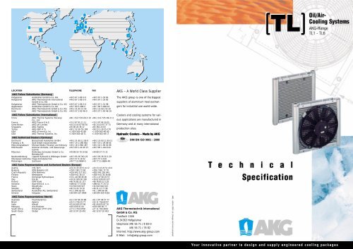
AKG – A World Class Supplier<br />
The AKG group is one of the biggest<br />
suppliers of aluminium heat exchangers<br />
for industrial use world-wide.<br />
Coolers and cooling systems for various<br />
applications are manufactured in<br />
Germany and at many international<br />
production sites.<br />
Hydraulic Coolers – Made by AKG<br />
DIN EN ISO 9001 : 2000<br />
AKG Thermotechnik International<br />
GmbH & Co. KG<br />
Postfach 1346<br />
D-34363 Hofgeismar<br />
telephone (49) 56 71 / 8 83-0<br />
fax (49) 56 71 / 35 82<br />
Internet: http://www.akg-group.com<br />
E-Mail: Info@akg-group.com<br />
AKG - edition 2005-1-E (changes and errors <strong>excepted</strong>)<br />
Your innovative partner to design and supply engineered cooling packages
Features<br />
• Cooling systems are made from Aluminium<br />
• Fully tried and tested for arduous working conditions<br />
• Ideal for mobile machines<br />
• Maximum working pressure 14 bar<br />
Oil/Air-<br />
Cooling Systems<br />
AKG-Range<br />
TL1 - TL6<br />
• Offering a high flexibility for usage in transmission, hydraulic,<br />
engine and lubrication oils<br />
• Cooling systems can be fitted with 12/24V DC and 3 Phase motors<br />
Benefits<br />
• Short lead times<br />
• Cost effective<br />
• Cooling systems fully equipped for<br />
immediate use<br />
• Easy to install<br />
(TL)<br />
General<br />
Our TL range is designed to help you find an<br />
individual solution for your cooling application.<br />
Our TL cooling systems offer a wide variety of<br />
products which have been fully tried and tested,<br />
even under arduous working conditions.<br />
• Spares from stock<br />
• Maintenance free<br />
A range of six basic types covers almost all<br />
cooling applications, involving a large variety of<br />
fluids in stationary and mobile machines.<br />
Applications<br />
AKG and its representatives as experts in the<br />
field of cooling systems will be delighted to<br />
assist you.<br />
As part of our ongoing technical improvements,<br />
AKG maintains the right to introduce modifications<br />
to the specifications in this brochure.<br />
The units can be<br />
used for cooling: mineral oil, synthetic oil, bio oil, HFA B C D liquids,<br />
water/glycol mixture, containing 50% antifreeze<br />
and corrosion inhibitors<br />
Function: Heat will be transferred from the fluid to the cooling<br />
air flow<br />
Please note:<br />
• Set up and operating instructions<br />
• General Terms of Sales and<br />
Delivery<br />
• Spares list<br />
Your partner for<br />
hydraulic coolers
Oil Out<br />
Technical Data<br />
E<br />
TL1 - TL6, with DC fan motor,... including shroud without shroud 3 Phase motor<br />
0<br />
(2x)<br />
A<br />
22<br />
F<br />
D<br />
H<br />
B<br />
SW 36<br />
LL 9 x12<br />
(P)<br />
40<br />
N max.<br />
N max.<br />
K<br />
55 55 55<br />
40<br />
K<br />
N max.<br />
Cooler Type<br />
Order Number<br />
Fan Diameter<br />
[mm]<br />
Fan Speed<br />
[rpm]<br />
Noise Level<br />
[dB(A),1m]<br />
TL1 5741.201.0000 140 4780 68 12 3.4 0.04 0.7 14 2.4<br />
5741.202.0000 140 4770 68 24 1.7 0.04 0.7 14 2.4<br />
TL2 5742.201.0000 167 4250 76 12 6.5 0.08 1.0 14 4.4<br />
5742.202.0000 167 4350 76 24 3.6 0.09 1.0 14 4.4<br />
5742.221.0000 167 4250 77 12 6.5 0.08 1.0 14 3.6<br />
5742.222.0000 167 4350 77 24 3.6 0.09 1.0 14 3.6<br />
5742.203.0000 170 1500 63 230/400 0.12 0.04 1.0 14 5.6<br />
Motor Voltage<br />
[V]<br />
Current<br />
[Amp]<br />
Power Consumption<br />
[kW]<br />
Volume<br />
[l]<br />
Working Pressure<br />
[bar]<br />
Total Weight<br />
excluding fluid [kg]<br />
44<br />
Oil In<br />
TL3 5743.201.0000 225 3400 76 12 7.7 0.09 1.1 14 5.5<br />
5743.202.0000 225 3260 76 24 3.9 0.09 1.1 14 5.5<br />
5743.221.0000 225 3400 76 12 7.7 0.09 1.1 14 4.6<br />
5743.222.0000 225 3260 76 24 3.9 0.09 1.1 14 4.6<br />
5743.203.0000 250 3000 81 230/400 0.79 0.25 1.1 14 12.0<br />
SPECIFICATION<br />
Cooler Type TL1 TL2 TL3 TL4 TL5 TL6<br />
Heat rejection 1) 1-4,5 2-7 3-13 5-16 6-20 10-35<br />
TL1-TL6, with DC fan motor, including shroud DIMENSIONS<br />
A mm 150 200 250 300 350 600<br />
B mm 154 203 252 301 350 301<br />
D mm 227 276 325 372 422 374<br />
E mm 238 288 338 388 438 688<br />
F mm 1 x 90 1 x 140 1 x 190 1 x 240 2 x 145 2 x 270<br />
H mm 184 233 282 331 380 331<br />
K mm 95 95 95 95 95<br />
N max. mm 145,5 147 147 147 147 147<br />
O G 1 /2 G 3 /4 G 3 /4 G 3 /4 G 3 /4 G 3 /4<br />
P mm 4x 4x 4x 4x 6x 6x<br />
A x B m 2 0.0231 0.0406 0.0630 0.0902 0.1223 0.1804<br />
Without shroud<br />
N max. mm – 107 107 107 107 107<br />
3 Phase motor<br />
K mm – 135 112 112 135 255<br />
N max. mm 180 320 320 380 510<br />
TL4 5744.201.0000 280 3280 80 12 9.2 0.12 1.7 14 7.4<br />
5744.202.0000 280 3260 80 24 4.7 0.12 1.7 14 7.4<br />
5744.221.0000 280 3280 79 12 9.2 0.12 1.7 14 6.2<br />
5744.222.0000 280 3260 79 24 4.7 0.12 1.7 14 6.2<br />
5744.203.0000 280 3000 82 230/400 0.79 0.25 1.7 14 14.0<br />
TL5 5745.201.0000 330 2600 75 12 7.9 0.10 2.0 14 8.3<br />
5745.202.0000 330 2620 75 24 4.1 0.10 2.0 14 8.3<br />
5745.221.0000 330 2600 71 12 7.9 0.10 2.0 14 7.0<br />
5745.222.0000 330 2620 71 24 4.1 0.10 2.0 14 7.0<br />
5745.203.0000 350 1500 72 230/400 0.5 0.12 2.0 14 15.0<br />
TL6 5746.201.0000 2 x 280 3280 85 12 2 x 9.2 2 x 0.12 2.4 14 13.0<br />
5746.202.0000 2 x 280 3260 85 24 2 x 4.7 2 x 0.12 2.4 14 13.0<br />
5746.221.0000 2 x 280 3280 81 12 2 x 9.2 2 x 0.12 2.4 14 14.0<br />
5746.222.0000 2 x 280 3260 81 24 2 x 4.7 2 x 0.12 2.4 14 14.0<br />
5746.203.0000 1 x 300 3000 81 230/400 1.0 0.37 2.4 14 20.0<br />
Materials<br />
3 Phase motor: B14 small flange<br />
Depending on the motor the current and power will vary.<br />
For details see the name plate.<br />
ORDER CODE SYSTEM<br />
574 . 2 . 0000<br />
Cooler:<br />
Fan blade:<br />
Shroud, Finger guard:<br />
Aluminium<br />
Plastic<br />
Steel (Zinc plated), Painted/Powder coated<br />
Cooler type: e.g. 2 = TL2<br />
Direction of cooling air flow: pulling<br />
01 = 12 V DC including shroud<br />
02 = 24 V DC including shroud<br />
03 = 3 Phase motor including shroud<br />
21 = 12 V DC without shroud<br />
22 = 24 V DC without shroud<br />
1) For details use diagrams and tables as appropriate<br />
2) All systems are pressure tested according to DIN 50104<br />
4 5<br />
Applications: Trucks Busses, Commercial Trucks, Fork-Lift Trucks, Special Vehicl es, Tractors, Concrete Mixer Trucks, Construction Machinery Asphalt Compactors,
Easy sizing of TL-coolers<br />
Easy sizing of TL-coolers<br />
The following tables may be used to quickly select a TL-cooler.<br />
The data is based on the assumption that oil inlet temperature does not exceed 70 °C for<br />
hydraulic and 110 °C for lubrication applications.<br />
For a more detailed and customised cooler selection exact temperatures and flows are necessary.<br />
Please select your cooler according to the example on page 10 or seek advice from AKG or its<br />
representatives.<br />
Please use the following heat rejection figures if no details are available:<br />
- Agricultural and construction machinery: 1/3 of Diesel engine power<br />
- Hydraulic pumps driven by an electric motor: 1/3 of electric motor power<br />
applications<br />
Hydraulic applications<br />
Lubrication oil applications<br />
Lubrication oil applications<br />
Heat rejection [kW @ 30 °C ambient temperature]<br />
Oil flow TL1 TL2 TL3 TL4 TL5 TL6 TL2 TL3 TL4 TL5 TL6<br />
in l/min<br />
Including shroud<br />
Without shroud, fitted with 12/24V DC fan motor<br />
10 1.8<br />
20 2.0 3.0 4.8 6.8 8.4 12.8 2.2 3.2 6.0 6.2 10.4<br />
30 2.2 3.2 5.2 7.0 8.6 13.2 2.4 3.6 6.2 6.4 10.8<br />
50 3.4 5.6 7.2 8.8 14.0 2.6 4.2 6.6 6.8 11.6<br />
60 3.6 5.8 7.4 9.0 14.4 2.8 4.4 6.8 7.2 12.2<br />
80 6.4 7.6 9.2 15.2 4.8 7.0 7.4 13.0<br />
100 8.0 9.4 16.0 7.2 7.8 13.2<br />
120 9.6 16.2 8.0 13.6<br />
150 16.4 14.4<br />
Heat rejection [kW @ 30 °C ambient temperature]<br />
Oil flow TL1 TL2 TL3 TL4 TL5 TL6 TL2 TL3 TL4 TL5 TL6<br />
in l/min<br />
Including shroud<br />
Without shroud, fitted with 12/24V DC fan motor<br />
10 3.6<br />
20 4.0 6.0 9.6 13.6 16.8 25.6 4.4 6.4 12.0 12.4 20.8<br />
30 4.4 6.4 10.4 14.0 17.2 26.4 4.8 7.2 12.4 12.8 21.6<br />
50 6.8 11.2 14.4 17.6 28.0 5.2 8.4 13.2 13.6 23.2<br />
60 7.2 11.6 14.8 18.0 28.8 5.6 8.8 13.6 14.4 24.4<br />
80 12.8 15.2 18.4 30.4 9.6 14.0 14.8 26.0<br />
100 16.0 18.8 32.0 14.4 15.6 26.4<br />
120 19.2 32.4 16.0 27.2<br />
150 32.8 28.8<br />
Heat rejection [kW @ 40 °C ambient temperature]<br />
Oil flow TL1 TL2 TL3 TL4 TL5 TL6 TL2 TL3 TL4 TL5 TL6<br />
in l/min<br />
Including shroud<br />
Without shroud, fitted with 12/24V DC fan motor<br />
10 1.4<br />
20 1.5 2.3 3.6 5.1 6.3 9.6 1.7 2.4 4.5 4.7 7.8<br />
30 1.7 2.4 3.9 5.3 6.5 9.9 1.8 2.7 4.7 4.8 8.1<br />
50 2.6 4.2 5.4 6.6 10.5 2.0 3.2 5.0 5.1 8.7<br />
60 2.7 4.4 5.6 6.8 10.8 2.1 3.3 5.1 5.4 9.2<br />
80 4.8 5.7 6.9 11.4 3.6 5.3 5.6 9.8<br />
100 6.0 7.1 12.0 5.4 5.9 9.9<br />
120 7.2 12.2 6.0 10.2<br />
150 12.3 10.8<br />
Heat rejection [kW @ 40 °C ambient temperature]<br />
Oil flow TL1 TL2 TL3 TL4 TL5 TL6 TL2 TL3 TL4 TL5 TL6<br />
in l/min<br />
Including shroud<br />
Without shroud, fitted with 12/24V DC fan motor<br />
10 3.2<br />
20 3.5 5.3 8.4 11.9 14.7 22.4 3.9 5.6 10.5 10.9 18.2<br />
30 3.9 5.6 9.1 12.3 15.1 23.1 4.2 6.3 10.9 11.2 18.9<br />
50 6.0 9.8 12.6 15.4 24.5 4.6 7.4 11.6 11.9 20.3<br />
60 6.3 10.2 13.0 15.8 25.2 4.9 7.7 11.9 12.6 21.4<br />
80 11.2 13.3 16.1 26.6 8.4 12.3 13.0 22.8<br />
100 14.0 16.5 28.0 12,.6 13.7 23.1<br />
120 16.8 28.4 14.0 23.8<br />
150 28.7 25.2<br />
6 7<br />
Building Machines, Compressors, Cranes, Crawlers, Drills, Excavators, Graders,<br />
Loaders, Pipe Layers, Scrapers, Screw Compressors, Vibration Rollers, Machines,
Specific heat rejection TL1 - TL6<br />
Pressure drop TL1 - TL6<br />
0,5<br />
PK/ETD (kW/K)<br />
∆p (bar)<br />
3<br />
TL6<br />
2,5<br />
TL6 InclS<br />
0,4<br />
2<br />
TL6 WS<br />
1,5<br />
0,3<br />
1<br />
TL5<br />
TL5 InclS<br />
0,5<br />
TL1<br />
TL3<br />
TL4<br />
0,2<br />
TL4 InclS<br />
TL5 WS<br />
TL2<br />
TL4 WS<br />
TL3 InclS<br />
0 20 40 60 80 100 120 140 160<br />
Oil flow (l/min)<br />
TL3 WS<br />
0,1<br />
TL2 InclS<br />
The pressure drop curves are based on a viscosity of 30 mm 2 /s = 30 cSt.<br />
Please use conversion factor f from page 11, to calculate pressure drop at other viscosity's.<br />
TL1<br />
TL2 WS<br />
0<br />
20 40 60 80 100 120 140 160<br />
Oil flow (l/min)<br />
InclS = Including shroud<br />
WS = Without shroud<br />
8 9<br />
Tools, Casting Machines, Elevators, Extrusion Machines, Forging Manipulators, Fo<br />
rging Presses, Gears, Hydraulic Systems, Pipe Bending Machines, Presses, Pumps,
Selecting a cooling system<br />
Conversion factors for different oil pressure drops<br />
To select a cooler for your application, the following data is required:<br />
The pressure drop curves on pages 9 are based on a viscosity of 30 mm 2 /s = 30 cSt.<br />
Please use conversion factor f to calculate pressure drop at other viscosities.<br />
● Heat rejection: Alternative terminology is dissipation<br />
● Oil flow: Circulating oil flow determines the cooler size<br />
● Oil inlet temperature: Temperature of the oil entering the cooler<br />
● Cooling air flow temperature: Air temperature at cooler face before entering matrix<br />
mm 2 , cSt<br />
s<br />
10 15 20 30 40 50 60 80 100<br />
f 0.5 0.65 0.75 1.0 1.2 1.4 1.6 2.1 2.8<br />
1. Determination of input data<br />
Preq [kW]<br />
VOil [l/min]<br />
TOil [°C]<br />
Tcaf [°C]<br />
Heat rejection<br />
Oil flow<br />
Oil inlet temperature<br />
Cooling air flow temperature<br />
2. Specific heat rejection<br />
ETD [K] = TOil - Tcaf Entering Temperature Difference<br />
Prshr [kW/K] = Preq / ETD required specific heat rejection<br />
Example<br />
Preq<br />
VOil<br />
= 10 kW<br />
= 50 l/min<br />
TOil = 70 °C<br />
Tcaf = 30 °C<br />
ETD [K] = TOil - Tcaf=> 70 °C - 30 °C = 40 °C (= 40 K)<br />
Prshr = Preq / ETD => 10 kW / 40 K = 0.25 kW/K<br />
Example:<br />
Pressure drop of type TL4 is 0.75 bar @ 90 l/min and 30 mm 2 /s.<br />
Assume an oil type ISO VG 46 is used @ 60 °C having a viscosity of 20 mm 2 /s.<br />
To calculate new pressure drop multiply 0.75 bar by f = 0.75 to obtain the actual pressure drop 0.6 bar<br />
approximately.<br />
Notes:<br />
3. Select according to diagram<br />
Pshr<br />
ETD<br />
0.3<br />
TL 6 WS<br />
(= without shroud)<br />
Pshr/ETD [kW/K] actual specific heat rejection<br />
P = (Pshr / ETD) x ETD actual heat rejection<br />
50 100<br />
Pshr /ETD = 0.3 kW/K =>TL6 WS<br />
P = 0.3 kW/K x 40 K = 12 kW<br />
Oil flow [l/min]<br />
4. Pressure drop /<br />
Oil temperature difference<br />
∆p<br />
[bar]<br />
TL6 WS<br />
Obtain pressure drop @ 30 cST oil viscosity from diagram<br />
on page 9. To calculate for other oil viscosities please use<br />
0.6<br />
example on page 11.<br />
∆TOil [°C] = 33 x P[kW] / VOil [l/min]<br />
50<br />
75<br />
Oil flow [l/min]<br />
∆TOil = 33 x (12 kW / 50 l/min) = 7.9 °C<br />
5. Results<br />
selected cooler TL6 WS: heat rejection 12 kW,<br />
oil temperature difference 7.9 °C,<br />
pressure drop 0.6 bar<br />
10 11<br />
Rolling Plants, Slab Shears, Scrap Shears, Transport Equipment, Vacuum Pumps, Ag<br />
riculture Chaffcutters, Combines, Forestry Machines, Harvest Machines, Tractors