Reactor Control Systems of Qinshan Phase III CANDU ... - canteach
Reactor Control Systems of Qinshan Phase III CANDU ... - canteach
Reactor Control Systems of Qinshan Phase III CANDU ... - canteach

Create successful ePaper yourself
Turn your PDF publications into a flip-book with our unique Google optimized e-Paper software.
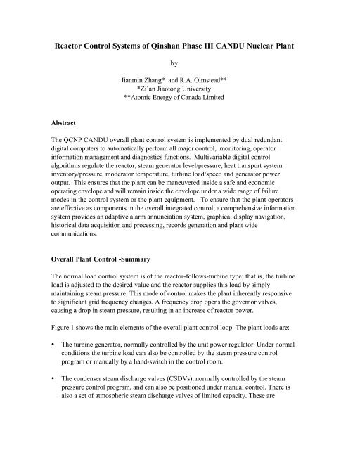
<strong>Reactor</strong> <strong>Control</strong> <strong>Systems</strong> <strong>of</strong> <strong>Qinshan</strong> <strong>Phase</strong> <strong>III</strong> <strong>CANDU</strong> Nuclear Plant<br />
Abstract<br />
by<br />
Jianmin Zhang* and R.A. Olmstead**<br />
*Zi’an Jiaotong University<br />
**Atomic Energy <strong>of</strong> Canada Limited<br />
The QCNP <strong>CANDU</strong> overall plant control system is implemented by dual redundant<br />
digital computers to automatically perform all major control, monitoring, operator<br />
information management and diagnostics functions. Multivariable digital control<br />
algorithms regulate the reactor, steam generator level/pressure, heat transport system<br />
inventory/pressure, moderator temperature, turbine load/speed and generator power<br />
output. This ensures that the plant can be maneuvered inside a safe and economic<br />
operating envelope and will remain inside the envelope under a wide range <strong>of</strong> failure<br />
modes in the control system or the plant equipment. To ensure that the plant operators<br />
are effective as components in the overall integrated control, a comprehensive information<br />
system provides an adaptive alarm annunciation system, graphical display navigation,<br />
historical data acquisition and processing, records generation and plant wide<br />
communications.<br />
Overall Plant <strong>Control</strong> -Summary<br />
The normal load control system is <strong>of</strong> the reactor-follows-turbine type; that is, the turbine<br />
load is adjusted to the desired value and the reactor supplies this load by simply<br />
maintaining steam pressure. This mode <strong>of</strong> control makes the plant inherently responsive<br />
to significant grid frequency changes. A frequency drop opens the governor valves,<br />
causing a drop in steam pressure, resulting in an increase <strong>of</strong> reactor power.<br />
Figure 1 shows the main elements <strong>of</strong> the overall plant control loop. The plant loads are:<br />
• The turbine generator, normally controlled by the unit power regulator. Under normal<br />
conditions the turbine load can also be controlled by the steam pressure control<br />
program or manually by a hand-switch in the control room.<br />
• The condenser steam discharge valves (CSDVs), normally controlled by the steam<br />
pressure control program, and can also be positioned under manual control. There is<br />
also a set <strong>of</strong> atmospheric steam discharge valves <strong>of</strong> limited capacity. These are
normally kept closed, but are available as a controllable heat sink when steam<br />
discharge to the condenser is not available.<br />
The main control programs and their functions are:<br />
a) Unit Power Regulator (UPR) - This is the turbine load control program, which<br />
changes turbine load as demanded by the operator and maintains generator output at<br />
the desired setpoint.<br />
b) Boiler Pressure <strong>Control</strong>ler (BPC) - The BPC program controls steam pressure to a<br />
constant setpoint by either changing the reactor power setpoint, or by adjusting the<br />
plant loads if it is not possible for the reactor to follow power demands. The SPC also<br />
controls the HTS warm-up and cool-down.<br />
c) <strong>Reactor</strong> Regulating System (RRS) - The reactor flux control program monitors various<br />
power demands to determine the reactor neutron power setpoint, and adjusts the<br />
reactor's reactivity devices to maintain power at that setpoint.<br />
Turbine and Relief Valve Auto/manual <strong>Control</strong><br />
Steam flow to the turbine, and therefore turbine power is determined by the governor<br />
valves whose opening depends on turbine load setpoint and turbine speed. The governor<br />
droop, i.e. frequency error to stroke governor valves fully, is typically 4%, but may be<br />
increased during synchronization. The turbine load setpoint can be raised or lowered at<br />
several rates. The slower rates are used for normal load maneuvers; the fast rates unload<br />
the set quickly during upset conditions such as reactor trips.<br />
An automatic/manual selector switch determines whether the turbine control commands<br />
originate from the computer, or from the turbine control panels.<br />
In the automatic mode, the commands can originate from one <strong>of</strong> three control programs:<br />
a) Turbine Run-Up - runs the turbine up to speed and block loads it after<br />
synchronization.<br />
b) Unit Power Regulator - controls the loading and unloading <strong>of</strong> the turbine in the normal<br />
mode.<br />
The primary function <strong>of</strong> the condenser steam discharge valve (CSDV) is to bypass steam<br />
to the condenser under turbine load rejection conditions. The CSDVs are normally<br />
controlled by the steam pressure control program on the basis <strong>of</strong> steam pressure error and<br />
reactor-turbine power mismatch. They may also be positioned, on operator request,<br />
through keyboard inputs to the computers.<br />
CJNPE_paper990401<br />
11/21/05<br />
2
Condenser steam discharge valve operation may be subject to a number <strong>of</strong> constraints<br />
(low condenser vacuum, turbine exhaust spray, high steam generator level) to avoid<br />
damage to the condenser or turbine.<br />
The valves have a stroking speed, typically one second, which is sufficient to avoid lifting<br />
the steam generator safety valves on a turbine trip from full power.<br />
The primary function <strong>of</strong> the atmospheric steam discharge valve is to provide a<br />
controllable heat sink when discharge to the condenser is not available. They are normally<br />
controlled by the steam pressure control program on the basis <strong>of</strong> steam pressure error,<br />
but with an <strong>of</strong>fset.<br />
The operator can override computer control <strong>of</strong> the ASDVs and either open or close these<br />
valves by a manual hand-switch.<br />
Reactivity Devices<br />
<strong>Reactor</strong><br />
CJNPE_paper990401<br />
11/21/05<br />
Overall Plant <strong>Control</strong><br />
HTS<br />
P CSDV<br />
Phi Pth Speed<br />
Figure 1<br />
Overall plant <strong>Control</strong> Diagram<br />
3<br />
ASDV<br />
Governor<br />
A<br />
N<br />
Turbine<br />
Condenser<br />
Generator<br />
RRS<br />
A<br />
N<br />
BPC UPR<br />
A N<br />
Computer<br />
A - Alternate N - Normal<br />
Boiler<br />
TT4<br />
Power Setpoint form Operator
<strong>Reactor</strong> Power Measuring Devices<br />
Three ion chambers mounted on the side <strong>of</strong> the reactor measure neutron flux over seven<br />
decades, 10 -7 full power to 1.5 full power. Solid-state amplifiers convert the ion chamber<br />
current into three sets <strong>of</strong> triplicated signals for use by the control computers:<br />
a) Log Neutron Power, 10 -7 to 1.5 full power<br />
b) Linear Neutron Power, 0 to 1.5 full power<br />
c) Rate <strong>of</strong> Change <strong>of</strong> Log Power, -15% to +15% <strong>of</strong> present power per second<br />
The log neutron power signal response time is typically a few milliseconds in the higher<br />
decades, increasing to approximately 20 seconds in the lowest decade. In the event <strong>of</strong><br />
extremely low power levels, such as those encountered in the initial criticality <strong>of</strong> the<br />
reactor during commissioning, a separate set <strong>of</strong> startup instrumentation is used.<br />
Twenty-eight platinum clad straight individually replaceable (SIR) in-core flux detectors<br />
measure reactor power over two decades, 10 -2 full power to 1.5 full power, in the<br />
fourteen power zones associated with liquid zone controllers. At each location there are<br />
two detectors for redundancy. Solid-state amplifiers convert the detector current to a<br />
suitable computer input signal. The control system transforms this computer input into a<br />
signal that closely matches corresponding changes in reactor power. The platinum-clad<br />
Inconel detectors have a relatively slow rate <strong>of</strong> burn-up (loss <strong>of</strong> sensitivity due to<br />
accumulated exposure to neutron flux).<br />
The detectors are characterized with a response approximately 90% prompt, 10%<br />
delayed, to changes in neutron flux. Thirty percent <strong>of</strong> the signal results from reactor<br />
gamma rays, one-third <strong>of</strong> which are delayed. This accounts for a major portion <strong>of</strong> the<br />
delayed signal generated by the detector. The overall response is a good representation <strong>of</strong><br />
the power-to-fuel dynamic characteristics <strong>of</strong> a <strong>CANDU</strong> reactor.<br />
Vanadium SIR in-core detectors measure neutron flux at 102 selected points throughout<br />
the core to determine reactor flux shape and local power levels. Amplifiers, similar to<br />
those for the platinum-clad detectors convert the vanadium detector current signals to<br />
corresponding computer input signals.<br />
Vanadium detectors are characterized by very slow burn-up in a high neutron flux and<br />
essentially 100% neutron response, but have a relatively slow response (5.4 minute time<br />
constant).<br />
At high power, total reactor thermal power is measured on the secondary side <strong>of</strong> the<br />
steam generators. It is based on redundant measurements <strong>of</strong> steam flow, steam pressure,<br />
feedwater flow and feedwater temperature. The measurement lags the actual reactor<br />
power to coolant by approximately twenty seconds due to transport delays and thermal<br />
time constants.<br />
CJNPE_paper990401<br />
11/21/05<br />
4
At low power, the total reactor thermal power is calculated from temperature rise<br />
measurements across the reactor. The regulating system controls total reactor flux level<br />
and flux tilt, the latter by equalizing measured power in 14 regions associated with 14<br />
liquid zone controllers. Spatial flux control is required only at relatively high reactor<br />
power (above 20% full power) where the possibility <strong>of</strong> xenon-induced instabilities exists.<br />
Total reactor power is determined by a combination <strong>of</strong> ion chamber signals (at low<br />
power) and platinum-clad in-core detector signals (at high power). The cross over occurs<br />
around 10% full power. Because neither measurement is absolute, the flux signals are<br />
continuously calibrated against reactor power measurements based on thermal signals.<br />
The 14 zone power measurements are based on the platinum-clad flux detectors. Absolute<br />
measurements are less important here because the spatial control system simply equalizes<br />
measurements. However, a single flux measurement may not be entirely representative <strong>of</strong><br />
the average power in a region <strong>of</strong> the core due to local flux disturbances caused by<br />
refuelling. Therefore, the platinum-clad detector signals are also calibrated continuously<br />
against vanadium detector measurements <strong>of</strong> average zone power.<br />
<strong>Reactor</strong> Regulating System (RRS)<br />
The reactor regulating system is that part <strong>of</strong> the overall plant control system that controls<br />
reactor power, and maneuvers reactor power in accordance with specified setpoints. See<br />
Figure 2.<br />
<strong>Reactor</strong><br />
Setpoint<br />
BPC<br />
Setbacks<br />
Operator<br />
Stepbacks<br />
Trips<br />
CJNPE_paper990401<br />
11/21/05<br />
Ep<br />
<strong>Reactor</strong> Regulating System<br />
Reactivity Devices<br />
Zone <strong>Control</strong>lers<br />
Absorbers<br />
Adjusters<br />
Poison Addition<br />
SOR Withdrawal<br />
Ri<br />
Neutronics<br />
Feedbacks<br />
Xenon<br />
Power Measurement<br />
& Calibration<br />
Feedbacks from<br />
Moderator Temp<br />
Fuel Temp<br />
Void<br />
Figure 2: <strong>Reactor</strong> Regulating System Block Diagram<br />
5<br />
Flux<br />
Detectors<br />
Fuel and<br />
Heat Transport Lags<br />
Instrumented<br />
Channels
During normal operation, the setpoint is calculated by the steam generator pressure<br />
control system to maintain constant steam pressure in the steam generator. During<br />
serious plant upsets, RRS provides controlled or fast power reduction automatically.<br />
RRS also responds to operator manual request for reactor power reduction or shutdown.<br />
The reactor regulating system is composed <strong>of</strong> input sensors (ion chambers, in-core flux<br />
detectors and process measurements), reactivity control devices (adjusters, light water<br />
zone controllers, mechanical control absorbers), hardware interlocks and display devices.<br />
<strong>Reactor</strong> Regulating System action is generally initiated by digital control computer (DCC)<br />
programs which process the inputs and drive the appropriate reactivity control and<br />
display devices.<br />
Functional Requirements<br />
a) To provide automatic control <strong>of</strong> reactor power to a setpoint at any power level<br />
between 10 -6 FP and Full Power as specified by the operator (ALTERNATE mode)<br />
or to the power level required to maintain steam pressure in the steam generators<br />
(Normal mode).<br />
b) To maneuver reactor power at controlled rates between any two power levels in the<br />
automatic control range (above 10 -6 FP).<br />
c) To insert or to remove reactivity devices at controlled rates to maintain a reactivity<br />
balance in the core. These devices compensate for variations in reactivity arising from<br />
changes in xenon concentration, fuel burnup, moderator poison concentration, or<br />
reactor power.<br />
d) To maintain the neutron flux distribution close to its nominal design shape, so that the<br />
reactor can operate at full power without violating bundle or channel power limits.<br />
The demand power routine computes the desired reactor power setpoint and compares it<br />
with the measured bulk power to generate a bulk power error signal that is used to<br />
operate the reactivity device.<br />
The primary reactivity control devices are the 14 liquid zone control absorbers. The<br />
reactivities inserted by the zone control absorbers are varied in unison for bulk power<br />
control or differentially for tilt control. If the reactivity required to maintain reactor flux<br />
power at its specified setpoint exceeds the capability <strong>of</strong> the liquid zone control system,<br />
the reactor regulating system programs call on the other reactivity devices. Adjusters are<br />
removed for positive reactivity shim. Negative reactivity is provided by the mechanical<br />
control absorbers or by poison addition to the moderator. The movement <strong>of</strong> these devices<br />
is controlled by average liquid zone controller level and the effective power error.<br />
In addition to controlling reactor power to a specified setpoint, the <strong>Reactor</strong> Regulating<br />
System performs the function <strong>of</strong> monitoring a number <strong>of</strong> important plant variables, and<br />
reducing the reactor power, when any <strong>of</strong> these variables exceed specified limits. This<br />
CJNPE_paper990401<br />
11/21/05<br />
6
power reduction may be fast (setback), or slow (setback), depending on the possible<br />
consequences <strong>of</strong> the variable lying outside its normal operating range.<br />
The signal processing logic associated with RRS, implemented in the duplicated control<br />
computers (DCC-X and -Y), are redundant and fail-safe in the s<strong>of</strong>tware and hardware.<br />
<strong>Reactor</strong> Power <strong>Control</strong> Calibration<br />
The reactor regulating system uses estimates <strong>of</strong> ion chambers and platinum-clad Inconel<br />
flux detectors to generate fast, approximate zone and bulk reactor powers. These<br />
estimates generate short-term power error signal to drive the zone controllers and stabilize<br />
the flux in the core. Over a longer time span, these signals are slowly calibrated to agree<br />
with more accurate estimates <strong>of</strong> reactor and zone powers calculated from thermal<br />
measurements and flux mapping respectively.<br />
a) Bulk Power Calibration<br />
The fast, approximate estimate <strong>of</strong> reactor power is obtained by either taking the median<br />
ion chamber signal (at powers below 5% FP), or the average <strong>of</strong> 28 in-core platinum-clad<br />
Inconel detectors (above 15% FP), or a mixture <strong>of</strong> both (5 to 15% FP). These signals are<br />
filtered and calibrated by comparison with estimates <strong>of</strong> reactor power based on thermal<br />
power measurements from one <strong>of</strong> the following two sources.<br />
- Twelve pairs <strong>of</strong> resistance temperature detectors (RTDs) in total are located on the<br />
reactor inlet and outlet headers. The average temperature rise generates an accurate<br />
estimate <strong>of</strong> reactor power, which is used to calibrate the platinum flux detector signals<br />
below 50% FP.<br />
- Above 70% FP, measurements <strong>of</strong> SG steam flow, feedwater flow, and feedwater<br />
temperature are used to estimate reactor thermal power based on average SG power<br />
calculation.<br />
- In the intermediate power range (50 to 70% FP) a linear combination <strong>of</strong> both<br />
estimates is utilized as the calibrating signal.<br />
Bulk calibration <strong>of</strong> platinum-clad inconel detectors is primarily to correct for the rather<br />
complicated dynamic relationship between the platinum-clad Inconel detector signal and<br />
the instantaneous fuel power. From the point <strong>of</strong> view <strong>of</strong> power generation and fuel<br />
integrity, fuel power is <strong>of</strong> most direct interest and must be closely regulated when the<br />
reactor is at or near full power.<br />
CJNPE_paper990401<br />
11/21/05<br />
7
) Spatial Power Calibration<br />
Short-term spatial control is based upon fast, approximate filtered measurements <strong>of</strong> zone<br />
power obtained by taking the average <strong>of</strong> the platinum-clad Inconel flux detectors in each<br />
zone. Long-term spatial control is achieved by calibrating the fast zone power<br />
measurements with accurate estimates <strong>of</strong> zone flux power obtained by processing the<br />
vanadium flux detector signals through the flux mapping routine. In the present design,<br />
flux mapping is used to provide an accurate estimate <strong>of</strong> average zone flux in each <strong>of</strong> the<br />
fourteen zones. These estimates are available once every two minutes (flux mapping<br />
sampling interval), and lag the neutron flux by approximately five minutes (vanadium<br />
detector time constant). Spatial calibration in a zone is done by matching the average zone<br />
flux estimate generated by flux mapping with appropriately filtered zone platinum-clad<br />
Inconel flux detector readings. This calibration is relative to the average <strong>of</strong> all zone fluxes<br />
and therefore flux mapping calibration cannot affect bulk reactor power. It does, however,<br />
improve spatial control. The flux mapping routine rejects individual detectors whose<br />
readings disagree significantly with the rest <strong>of</strong> the detectors. The net result is a smoothed<br />
accurate steady state estimate <strong>of</strong> relative zone power.<br />
Fail-Safe Operation<br />
The reactor power measurement and calibration are made as tolerant as possible to the<br />
sudden loss <strong>of</strong> various measurements. A number <strong>of</strong> spread checks ensure that all<br />
measurements are in reasonable agreement. Measurements that fail the spread check are<br />
rejected.<br />
For some measurement faults such as loss <strong>of</strong> two or more ion chamber log readings at low<br />
power or loss <strong>of</strong> six or more pairs <strong>of</strong> platinum detector readings at high power, there is no<br />
recourse but to fail the program in the controlling computer. Failure <strong>of</strong> the program in the<br />
controlling computer results in a transfer <strong>of</strong> control to the standby computer. If the<br />
program in the second computer detects the same measurement faults, it will fail too,<br />
causing the liquid zone control units to flood, i.e., fail safe.<br />
The regulating program is designed to fail safe on irrational control signals (e.g. if at less<br />
than 5% FP the median ion chamber signal is irrational). During a reactor startup, the<br />
operator manually raises power to -6 decades at which point the computer automatically<br />
takes over control. Special s<strong>of</strong>tware provisions facilitate a smooth transition between<br />
operator and automatic control.<br />
Demand Power Routine<br />
The demand power routine serves three functions:<br />
a) it determines the mode <strong>of</strong> operation <strong>of</strong> the plant,<br />
CJNPE_paper990401<br />
11/21/05<br />
8
) it calculates the reactor setpoint, and the effective power error that is used for driving<br />
the<br />
c) reactivity control devices,<br />
d) it automatically adds poison to the moderator if required.<br />
The source <strong>of</strong> the reactor power request depends upon the selected operating mode.<br />
In the Normal mode, where the reactor follows the turbine, the request comes from the<br />
steam generator pressure control program. Maneuvering rate limits are built into the<br />
demand power routine. The maximum power maneuvering rate requested is 1% FP per<br />
second above 25% FP and those below 25% FP are:<br />
%FP NORMAL Mode ALTERNATE Mode<br />
10 - 25 4% present power per second 4% present power per second<br />
< 10 1% present power per second 4% present power per second<br />
In the Alternate mode, where the turbine follows the reactor, the requested power is set<br />
by the operator who also selects the maneuvering rate. This mode is used on plant upsets<br />
or at low power when the steam generator pressure is insensitive to reactor power.<br />
During reactor setback, the demand power routine receives a negative maneuvering rate<br />
from the setback routine. Should the reactor be already reducing power at a greater rate,<br />
the setback rate is ignored; otherwise the setpoint is ramped down at the setback rate.<br />
The plant will be switched to Alternate Mode when the setback clears.<br />
The effective power error is calculated as a weighted sum <strong>of</strong> (a) the difference between the<br />
calibrated log power and reactor demanded log power setpoint and (b) the difference<br />
between the lograte and demanded maneuvering rate. If the effective power error exceeds<br />
10% for at least two seconds and the rate <strong>of</strong> power increase is positive, the demand<br />
power routine adds gadolinium poison to the moderator at the rate <strong>of</strong> 0.75 milli-k/minute.<br />
This automatic addition <strong>of</strong> poison prevents loss <strong>of</strong> regulation due to slow growth <strong>of</strong><br />
unforeseen reactivity excess in the core and also that resulting from a decreased reactivity<br />
load due to the decay <strong>of</strong> xenon when the plant has been shutdown for extended periods.<br />
The operator has the option <strong>of</strong> overriding this automatic poison addition.<br />
A deviation limiter prevents the power setpoint from exceeding 1.05 times the actual<br />
power to prevent power increases at large rates.<br />
Reactivity <strong>Control</strong> and Flux Shaping<br />
The functions <strong>of</strong> reactivity control and flux shaping are performed by the light water zone<br />
control absorbers, the adjusters and the mechanical control absorbers.<br />
CJNPE_paper990401<br />
11/21/05<br />
9
These different kinds <strong>of</strong> reactivity control devices are provided for diversity such that<br />
failure <strong>of</strong> one set can be overcome by negative reactivity from another set.<br />
The primary method <strong>of</strong> short term reactivity control is by varying the levels in the 14<br />
liquid zone control absorbers. Normally, adjusters are fully inserted, mechanical control<br />
absorbers are fully withdrawn and the average zone level is between 20% and 70% full.<br />
The liquid zone control program converts the power errors into lift signals to the liquid<br />
zone control valves. The total lift signal to a given liquid zone control valve consists <strong>of</strong> a<br />
signal proportional to the effective power error plus a differential component<br />
proportional to the zone power error and zone level error at low power.<br />
A shortage <strong>of</strong> negative reactivity is indicated by high zone controller water level and/or a<br />
large positive power error. In this case the mechanical control absorbers are driven into<br />
the core in two banks. In the case <strong>of</strong> a shortage <strong>of</strong> positive reactivity, indicated by low<br />
zone controller water level or a large negative power error, adjusters are driven out in<br />
banks according to a fixed sequence.<br />
Adjusters and mechanical control absorbers are driven out at a speed based on power<br />
error. This reduces the shim reactivity rate at low power errors, and enables the zone<br />
controllers to <strong>of</strong>fset the inserted reactivity with minimum power disturbances.<br />
<strong>CANDU</strong> 6 Digital <strong>Control</strong> Centre<br />
The <strong>CANDU</strong> 6 <strong>Control</strong> Centre combines the well-established operations interface and<br />
control systems, proven through 70 reactor-years <strong>of</strong> operation, with advanced features<br />
developed and pro<strong>of</strong>-tested at AECL, to deliver a state <strong>of</strong> the art set <strong>of</strong> features and<br />
benefits.<br />
The <strong>CANDU</strong> 6 control centre design is founded on proven systems, components and<br />
technology and only incorporates improvements with proven features and systems. The<br />
control centre design maintains all the elements demonstrated to be successful in operating<br />
<strong>CANDU</strong> units. Additionally, improvements have been made and performance tested as<br />
an integrated whole in AECLs mockup at Sheridan Park and in various implemented<br />
applications in operating <strong>CANDU</strong> plants (Gentilly-2, Bruce B, Bruce A, Pickering A,<br />
Pickering B). An artists' impression <strong>of</strong> the latest generation Main <strong>Control</strong> Room is<br />
included in Figure 3.<br />
CJNPE_paper990401<br />
11/21/05<br />
10
CJNPE_paper990401<br />
11/21/05<br />
Figure 3<br />
QCNP <strong>CANDU</strong> 6 <strong>Control</strong> Centre<br />
Preliminary Draft<br />
The typical <strong>CANDU</strong> 6 MCR provides a central location for the control and monitoring<br />
activities essential to the safe and reliable operation <strong>of</strong> a <strong>CANDU</strong> station. The overall unit<br />
controls are CRT based at the operator console using setpoint control through two dual<br />
redundant Digital <strong>Control</strong> Computers (DCCs), while the system and component controls<br />
are at the MCR panels. To achieve this, the control room can be thought <strong>of</strong> as a<br />
combination <strong>of</strong> digital systems and conventional process control systems supervised by<br />
human operators using computer displays, and conventional instrumentation and controls<br />
from the main control room (MCR). A significant amount <strong>of</strong> direct control <strong>of</strong> the process<br />
is achieved through computerized control with the DCC providing the operators a<br />
window into the process and the capability establish set-points for automated functions<br />
or to intervene in the control <strong>of</strong> the process as required. The use <strong>of</strong> computerized control<br />
and display permits the operation <strong>of</strong> the plant by a single operator during most normal<br />
situations. Operation from the Main <strong>Control</strong> Room is supported by a series <strong>of</strong> facilities:<br />
The <strong>Control</strong> Equipment Room, Computer Hardware Room, Shift Supervisors Area,<br />
Technical Support Centre, Emergency Response Centre, Work <strong>Control</strong> Area, <strong>Control</strong><br />
Computer Equipment Room and Computer Office.<br />
A secondary control area (SCA) is included in the <strong>CANDU</strong> 6 design as an alternate<br />
operational control facility. The SCA is used if the MCR becomes uninhabitable or nonfunctional<br />
for any reason (e.g., fire, toxic gas). Instrumentation and controls necessary for<br />
11
establishing and maintaining the plant in a safe shutdown state have been provided in the<br />
SCA. This contains the controls <strong>of</strong> Shutdown System 2, Containment System and<br />
portions <strong>of</strong> the Emergency Core Cooling functions, Post Accident Monitoring (PAM)<br />
instrumentation and information as required for expected use <strong>of</strong> the SCA, Emergency<br />
Water Supply controls and Emergency Power Supply as provided by the emergency<br />
diesel generators.<br />
Digital <strong>Systems</strong><br />
Overall, <strong>CANDU</strong> 6 plant control is highly automated, so that the operator's role is to<br />
provide top level commands and to monitor and supervise rather than carry out manual<br />
control. This control is augmented by fully automated safety system action which affords<br />
a long operator grace period for decision making in the event <strong>of</strong> any upsets or accidents.<br />
The QCNP control system consists <strong>of</strong> two independent digital computer control systems<br />
DCCX and DCCY with a combined reliability <strong>of</strong> 99.99%.<br />
The DCC computers also provide process monitoring and control through the computer<br />
interface. A separate digital computer system, the Plant Display System (PDS), drives<br />
supplementary plant process monitoring displays and performs alarm annunciation. This<br />
system is designed to support higher levels <strong>of</strong> information processing in support <strong>of</strong><br />
operator diagnostic and decision-making tasks and improve the operators awareness <strong>of</strong><br />
the state <strong>of</strong> the plant at all times.<br />
Safety <strong>Systems</strong> (<strong>Reactor</strong> Protection)<br />
Automatic control and safety system functions give the operator a period <strong>of</strong> 2 hours<br />
before safety critical response is needed for single initiating events. Even for hypothetical<br />
"dual failure" events, where an initiating event is assumed coincident with a safety system<br />
failure, a grace period <strong>of</strong> 15 minutes is built-in to design.<br />
Plant Computer <strong>Control</strong><br />
The plant control computers control all major functions including the reactor, the<br />
moderator, the heat transport, and the turbine systems. Continuous direct digital control<br />
<strong>of</strong> the reactor by manipulation <strong>of</strong> reactivity control devices <strong>of</strong>fer optimum reactor<br />
performance at all times. In the event <strong>of</strong> detected abnormal conditions, direct digital<br />
control <strong>of</strong> reactor power using setback and stepback power reduction algorithms avoid<br />
tripping <strong>of</strong> the system by special safety shutdown systems. This permits quick<br />
correction <strong>of</strong> process abnormalities and a return to power production. Process control<br />
programs <strong>of</strong> the DCCs perform direct digital control <strong>of</strong> steam pressure, moderator<br />
temperature, steam generator level, heat transport system, turbine speed and load and<br />
fueling machines. The major processes are all under full computer control from all states<br />
CJNPE_paper990401<br />
11/21/05<br />
12
from zero-power hot to electricity generation with operator supervisory control (setpoint<br />
entry for overall plant state). Fuel handling is carried out on-line, with a high degree <strong>of</strong><br />
computer control. The operator's role is to direct the steps digital control steps <strong>of</strong> the<br />
fueling operation.<br />
QCNP Plant Information Management<br />
The <strong>CANDU</strong> 6 plant display system (PDS) employs the new Advanced <strong>Control</strong> Centre<br />
Information System (ACCIS) technology and is designed to:<br />
• Protect against obsolescence, support continued growth and changes to the system<br />
over the life <strong>of</strong> the station, and provides the platform for the various computerized<br />
operator display applications advanced alarm system, process monitoring displays,<br />
and large overview displays.<br />
The Computerized Annunciation Message List System (CAMLS), validated in full-scope<br />
simulators using licensed operators from <strong>CANDU</strong> stations, is a digital system that<br />
achieves a reduction in station operating costs due to the following:<br />
• Reduces operator distraction and cognitive workload, provides support for rapid and<br />
efficient upset response, plant stabilization, problem diagnosis, and rapid recovery<br />
actions.<br />
• Improves operator communication and reduces communication errors<br />
• Improves interpretation <strong>of</strong> plant state and its impact on operating goals<br />
• Provides easier detection <strong>of</strong> secondary faults<br />
• Prevents <strong>of</strong> equipment damage<br />
• Reduces staffing required for monitoring during upsets and emergencies<br />
The suite <strong>of</strong> <strong>CANDU</strong> 6 process monitoring displays has been updated to include a set <strong>of</strong><br />
higher-level overview displays in addition to the system and component level displays<br />
that currently exist. The benefits attributed to the new displays include:<br />
• Enhanced operator plant state monitoring and situation awareness<br />
• Reduced operator cognitive workload<br />
• Faster and more accurate diagnoses<br />
• Reduction in human error<br />
• Increase in error-catching by the operational staff<br />
• Reduced in operating and maintenance costs<br />
• Enhance information provided for the various emergency response facilities<br />
Large Overview displays are a significant addition to the control room and are designed to<br />
improve support for situation awareness and operating crew teamwork. The displays<br />
CJNPE_paper990401<br />
11/21/05<br />
13
provide the operator with a vehicle to display any <strong>of</strong> the PDS displays in a format that<br />
supports viewing by everyone in the control room. The displays are therefore dynamic<br />
and can be selected to maximize the benefit to the operators for the different operating<br />
situations <strong>of</strong> the plant (shutdown/outage through power productions and emergencies). In<br />
addition to the benefits <strong>of</strong> the improved display suite, the use <strong>of</strong> central large screen<br />
displays provides the following benefits:<br />
• Enhanced operator communication and reduced communication errors<br />
• Enhanced human error recovery to permit corrections before the significant<br />
consequences are realized<br />
• Reduced in unplanned outages and enhanced recovery from planned and unplanned<br />
outages<br />
The new <strong>CANDU</strong> 6 control room incorporates an enhanced main VDU-based sit-down<br />
console. Here a single operator can monitor and control normal plant operations from<br />
shutdown to full power, without requiring operation at stand-up panels. The four VDUs<br />
and improved console design and layout provide enhance operator support for:<br />
• Safety system and critical safety parameter monitoring at the console following an<br />
upset, and<br />
• Monitoring and diagnosis <strong>of</strong> plant processes including interrogation <strong>of</strong> annunciation.<br />
The PDS is also designed to support the storage <strong>of</strong> data on-line for 24hrs and the<br />
extraction <strong>of</strong> data to <strong>of</strong>f-line media to support process surveillance and health monitoring.<br />
Conventional <strong>Systems</strong><br />
The control concept provides for conventional technology to control and monitor the<br />
plant during and following design basis events. It provides redundancy and reliability to<br />
plant control when assurance <strong>of</strong> the functioning <strong>of</strong> digital equipment may be difficult or <strong>of</strong><br />
concern. The conventional panels are also used to control and maneuver the individual<br />
systems <strong>of</strong> the plant during shutdown states and portions <strong>of</strong> warm-up and cooldown for<br />
local system alignment. This permits operators to maintain training and familiarization<br />
with the controls algorithms that are designed to be independent <strong>of</strong> each other, to be<br />
immune to single faulty inputs and to do checks on their outputs. These requirements are<br />
met by ensuring that each program reads in all the inputs it requires, then control modules<br />
are designed to be independent <strong>of</strong> each other, to be immune to single faulty inputs and to<br />
do checks on their outputs. These requirements are met by ensuring that each program<br />
reads in all the inputs it requires, the control algorithms are designed to be independent <strong>of</strong><br />
each other, to be immune to single faulty inputs and to do checks on their outputs.<br />
CJNPE_paper990401<br />
11/21/05<br />
14
Conclusion<br />
The QCNP overall plant control system is a combination <strong>of</strong> highly reliable, fault tolerant,<br />
multivariable computer control and automation plus a comprehensive operator<br />
information capability supporting plant operator supervision and coordination activities.<br />
Some other benefits:<br />
The Features:<br />
• Improved <strong>Control</strong> Centre Layout<br />
- Ergonomically designed consoles with improved operational support built-in (key procedures<br />
at hand, document/drawing layout space)<br />
- Large Screen Displays - Team Oriented<br />
• The large overview displays are two video display units centrally located in the control<br />
room<br />
• Provides the operating team with information to remain up-to-date with the overall state<br />
and trend <strong>of</strong> the plant<br />
• Focuses operating staff attention on the areas <strong>of</strong> plant operation <strong>of</strong> most importance for<br />
the current operating goals and plant state (Situation Awareness - SA)<br />
• Establishes a clear link between overall state and trends <strong>of</strong> the plant and displays<br />
containing process and equipment detail (SA and Direct Task Support)<br />
• Provides a common frame <strong>of</strong> reference for control room staff communication and problem<br />
solving (Teamwork) that improves<br />
• operator communication and reduce communication errors<br />
• error detection through enhanced team work support<br />
• interpretation <strong>of</strong> plant state and its impact on current operating goals (e.g., heat sink<br />
states)<br />
- Addition <strong>of</strong> dedicated emergency response facilities with full viewing <strong>of</strong> Plant Display<br />
System including Alarms and Alarm Interrogation<br />
• Technical Support Centre<br />
• Data links to <strong>of</strong>f-site emergency coordination facility and ability to connect remote Plant<br />
Display Nodes<br />
• Advanced Plant Display System - Proven, Off-the-shelf, Powerful<br />
- The Technology<br />
• Off-the-shelf components in a modular design<br />
• High speed data distribution inside and outside the MCR<br />
• High level <strong>of</strong> S<strong>of</strong>tware QA<br />
- The Functionality<br />
• Advanced design for computerized monitoring <strong>of</strong> plant functions related to supervisory<br />
control <strong>of</strong> systems<br />
• Alarms integrated into process monitoring displays<br />
• Advance alarm management and interrogation capabilities with access to alarm sheets<br />
• Plant, Safety, and Major function overview displays linked directly to lower level<br />
displays.<br />
• Advanced display navigation<br />
CJNPE_paper990401<br />
11/21/05<br />
15<br />
Continued …
The Benefits:<br />
• Enhanced Safety<br />
- Improved emergency response capabilities through computerized plant safety state monitoring<br />
- Displays and information available in the Technical Support Centre and transmitted to the<br />
<strong>of</strong>f-site emergency coordination facility<br />
• Operating and Maintenance cost reduction<br />
- Easier monitoring for technical specification/operating policy & procedure compliance<br />
- Increased component and equipment protection from abnormal events<br />
- Improved human performance in the areas <strong>of</strong> plant state monitoring and awareness, diagnosis<br />
and decision-making, error reduction and catching, communication, teamwork, vigilance, and<br />
workload<br />
- Maintenance cost reduction through enhanced monitoring <strong>of</strong> processes and equipment<br />
- Reduction in number, duration, or severity <strong>of</strong> unplanned outages<br />
- Capability for Data transmission to technical process surveillance groups to support<br />
condition-based monitoring and other predictive maintenance systems.<br />
• Improved Operator Performance<br />
- Enhanced operator plant state monitoring and situation awareness<br />
- Improved awareness <strong>of</strong> the state <strong>of</strong> the plant and component health when controlling systems<br />
or components - reduced operator error, equipment protection<br />
- Reduced operator cognitive workload<br />
- Faster and more accurate diagnoses<br />
- Reduction in human error and an increase in error-catching by the operational staff<br />
- Improved display navigation - faster, more accurate display selection designed to match<br />
operational tasks<br />
- Improved monitoring <strong>of</strong> computer systems health and performance<br />
- Enhanced operator communication and reduced communication errors<br />
• Improved Operator Consoles<br />
- Improved operational support and decreased Operating and Maintenance Costs<br />
• enhanced support for Primary Upset and Emergency Response<br />
• supports Independent Critical Safety Parameter Monitoring<br />
• increased desktop layout space<br />
• enhanced procedure storage and retrieval<br />
• enhanced filing and bookshelf storage for administration, procedures, permits, etc.<br />
• Enhanced control room architecture<br />
- based on human factors principles<br />
- enhanced appearance/aesthetics<br />
- improved operating staff vigilance and performance<br />
- operational pride in the facility<br />
- circadian rhythm control to improve operator performance in shift work applications.<br />
CAMLS Details<br />
Advanced alarm system: Computerized Annunciation Message List System (CAMLS)<br />
Operationally Focused<br />
The Features:<br />
- Alerts operators to changes in plant conditions that may impact on safety and production<br />
- Helps staff to effectively respond to all events and situations.<br />
- Provides a clear and concise overview <strong>of</strong> the current problems or faults in the plant<br />
- Provides an overview <strong>of</strong> the current state <strong>of</strong> the plant in the context <strong>of</strong> the current plant state<br />
(mode)<br />
- Provides support for specific operational tasks:<br />
• rapid and efficient upset response<br />
• plant stabilization<br />
• problem diagnosis<br />
• recovery action planning and implementation<br />
• rapid recovery from trip and return to power operation<br />
CJNPE_paper990401<br />
11/21/05<br />
16
- CAMLS has been validated in full-scope simulators using licensed operators at two different<br />
operating <strong>CANDU</strong> stations.<br />
The Benefits:<br />
- Up to 65% reduction in alarm data without the loss <strong>of</strong> relevant information<br />
- Reduction in operator distraction<br />
- Easier detection <strong>of</strong> secondary faults<br />
- Prevention <strong>of</strong> equipment damage<br />
- Support for plant upset recovery tasks<br />
- Shorter return to power from outages or upsets<br />
- Reduced operator workload and human error<br />
- Improved operator diagnosis and decision-making<br />
- Reduced staffing required for monitoring during upsets and emergencies<br />
- Many $ saved in operating costs (estimated by several stations at >$500k per year in reduced<br />
operating costs)<br />
CJNPE_paper990401<br />
11/21/05<br />
17