DA 50 DAF 50 6-10-10 XX
DA 50, DAF 50 6- 0- 0 XX
DA 50, DAF 50 6- 0- 0 XX

You also want an ePaper? Increase the reach of your titles
YUMPU automatically turns print PDFs into web optimized ePapers that Google loves.
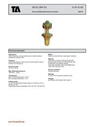
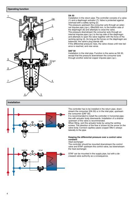
Operating function<br />
1<br />
2<br />
p-<br />
<strong>DA</strong> <strong>50</strong><br />
Installation in the return pipe. The controller consists of a valve<br />
(1) and a diaphragm actuator (7). Valve is protected against<br />
overload with a safety spring (2).<br />
The pressure upstream the consumer acts through an external<br />
impulse pipe (Dp+), Ø6x2<strong>50</strong>0 mm, to the bottom side of<br />
the diaphragm (8) and attempts to close the valve.<br />
The pressure downstream the consumer acts through an<br />
internal impulse pipe (Dp-) to the top side of the diaphragm<br />
and attempts to open the valve together with the force of the<br />
working spring (4). As long as the forces on the diaphragm are<br />
balanced, the valve’s plug stands still.<br />
If the differential pressure rises, the valve closes until new balance<br />
is reached, and vise versa.<br />
<strong>DA</strong>F <strong>50</strong><br />
Installation in the inlet pipe. Function is the same as <strong>DA</strong> <strong>50</strong>,<br />
except that the pressure downstream the consumer acts<br />
through another external copper impulse pipe (Dp-).<br />
7<br />
4<br />
Installation<br />
<strong>DA</strong> <strong>50</strong><br />
M<br />
STAF<br />
The controller has to be installed in the return pipe, downstream<br />
the consumer (<strong>DA</strong> <strong>50</strong>) or in the inlet pipe, upstream<br />
the consumer (<strong>DA</strong>F <strong>50</strong>).<br />
It is recommended to install the controller in horizontal pipeline<br />
with actuator body downwards. Installation of a strainer<br />
upstream of the valve is recommended.<br />
When filling, vent the actuator body by using the venting<br />
screws. The direction of the flow is shown by the arrow on the<br />
valve body. Connect capillary pipes (copper Ø6x1) always<br />
laterally to the pipe.<br />
<strong>DA</strong>F <strong>50</strong><br />
M<br />
STAF<br />
Keeping the differential pressure over a control valve<br />
constant<br />
Heat exchanger<br />
The controller should be mounted downstream the control<br />
valve and STAF upstream the control valve, but downstream<br />
the heat exchanger.<br />
STAF can be mounted in the supply pipe, but with a decreased<br />
valve authority as a consequence.