DA 50 DAF 50 6-10-10 XX
DA 50, DAF 50 6- 0- 0 XX
DA 50, DAF 50 6- 0- 0 XX

You also want an ePaper? Increase the reach of your titles
YUMPU automatically turns print PDFs into web optimized ePapers that Google loves.
<strong>DA</strong> <strong>50</strong>, <strong>DA</strong>F <strong>50</strong><br />
6-<strong>10</strong>-<strong>10</strong> <strong>XX</strong><br />
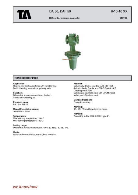
Differential pressure controller 2007.06<br />
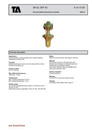
Technical description<br />
Application:<br />
Heating and cooling systems with variable flow.<br />
District heating substations, primary side.<br />
Function:<br />
Differential pressure control over the load.<br />
Closes at increasing Dp.<br />
Pressure class:<br />
PN 16 or PN 25<br />
Max. differential pressure:<br />
1600 kPa = 16 bar<br />
Temperature:<br />
Max. working temperature: 1<strong>50</strong>°C<br />
Min. working temperature: -<strong>10</strong>°C<br />
Material:<br />
Valve body: Ductile iron EN-GJS-400-18LT<br />
Actuator body: Ductile iron EN-GJS-400-18LT<br />
Diaphragms: EPDM<br />
Valve plug: Stainless steel with EPDM insert.<br />
Valve seat: Stainless steel.<br />
Surface treatment:<br />
Duasolid painting.<br />
Marking:<br />
TA, DN, PN and flow direction arrow.<br />
Flanges:<br />
According to EN-<strong>10</strong>92-2:1997, type 21.<br />
Setting range:<br />
Differential pressure adjustable <strong>10</strong>-60, <strong>50</strong>-1<strong>50</strong>, 130-2<strong>50</strong> kPa.<br />
Media:<br />
Water and neutral fluids, water-glycol mixtures.
<strong>DA</strong> <strong>50</strong><br />
L<br />
<strong>10</strong>-60 kPa<br />
D<br />
H2<br />
H1<br />
TA No DN D L H1 H2 Kvs Kg<br />
PN 16<br />
52 780-565 65 185 290 580 135 55 55<br />
52 780-590 <strong>10</strong>0 235 3<strong>50</strong> 680 175 120 88<br />
52 780-591 125 270 400 690 190 145 <strong>10</strong>5<br />
52 780-592 1<strong>50</strong> 300 480 775 227 230 235<br />
52 780-593 200 360 600 822 260 360 297<br />
PN 25 (DN 32-<strong>50</strong> and DN 80 also fit PN 16 flanges)<br />
52 780-132 32 140 180 535 <strong>10</strong>2 21 38<br />
52 780-140 40 1<strong>50</strong> 200 535 <strong>10</strong>2 25 39<br />
52 780-1<strong>50</strong> <strong>50</strong> 165 230 560 116 32 46<br />
52 780-165 65 185 290 580 135 55 55<br />
52 780-180 80 200 3<strong>10</strong> 592 149 70 66<br />
52 780-190 <strong>10</strong>0 235 3<strong>50</strong> 680 175 120 88<br />
52 780-191 125 270 400 690 190 145 <strong>10</strong>5<br />
52 780-192 1<strong>50</strong> 300 480 775 227 230 235<br />
52 780-193 200 360 600 822 260 360 297<br />
<strong>50</strong>-1<strong>50</strong> kPa<br />
TA No DN D L H1 H2 Kvs Kg<br />
Ø276<br />
Capillary pipe (Ø6) included: 2 <strong>50</strong>0 mm<br />
→ = Flow direction<br />
PN 16<br />
52 780-665 65 185 290 580 135 55 55<br />
52 780-690 <strong>10</strong>0 235 3<strong>50</strong> 680 175 120 88<br />
52 780-691 125 270 400 690 190 145 <strong>10</strong>5<br />
52 780-692 1<strong>50</strong> 300 480 775 227 230 235<br />
52 780-693 200 360 600 822 260 360 297<br />
PN 25 (DN 32-<strong>50</strong> and DN 80 also fit PN 16 flanges)<br />
52 780-232 32 140 180 535 <strong>10</strong>2 21 38<br />
52 780-240 40 1<strong>50</strong> 200 535 <strong>10</strong>2 25 39<br />
52 780-2<strong>50</strong> <strong>50</strong> 165 230 560 116 32 46<br />
52 780-265 65 185 290 580 135 55 55<br />
52 780-280 80 200 3<strong>10</strong> 592 149 70 66<br />
52 780-290 <strong>10</strong>0 235 3<strong>50</strong> 680 175 120 88<br />
52 780-291 125 270 400 690 190 145 <strong>10</strong>5<br />
52 780-292 1<strong>50</strong> 300 480 775 227 230 235<br />
52 780-293 200 360 600 822 260 360 297<br />
130-2<strong>50</strong> kPa<br />
TA No DN D L H1 H2 Kvs Kg<br />
PN 16<br />
52 780-765 65 185 290 580 135 55 55<br />
52 780-790 <strong>10</strong>0 235 3<strong>50</strong> 680 175 120 88<br />
52 780-791 125 270 400 690 190 145 <strong>10</strong>5<br />
52 780-792 1<strong>50</strong> 300 480 775 227 230 235<br />
52 780-793 200 360 600 822 260 360 297<br />
PN 25 (DN 32-<strong>50</strong> and DN 80 also fit PN 16 flanges)<br />
52 780-332 32 140 180 535 <strong>10</strong>2 21 38<br />
52 780-340 40 1<strong>50</strong> 200 535 <strong>10</strong>2 25 39<br />
52 780-3<strong>50</strong> <strong>50</strong> 165 230 560 116 32 46<br />
52 780-365 65 185 290 580 135 55 55<br />
52 780-380 80 200 3<strong>10</strong> 592 149 70 66<br />
52 780-390 <strong>10</strong>0 235 3<strong>50</strong> 680 175 120 88<br />
52 780-391 125 270 400 690 190 145 <strong>10</strong>5<br />
52 780-392 1<strong>50</strong> 300 480 775 227 230 235<br />
52 780-393 200 360 600 822 260 360 297
<strong>DA</strong>F <strong>50</strong><br />
L<br />
<strong>10</strong>-60 kPa<br />
TA No DN D L H1 H2 Kvs Kg<br />
D<br />
H2<br />
H1<br />
PN 16<br />
52 785-565 65 185 290 580 135 55 55<br />
52 785-590 <strong>10</strong>0 235 3<strong>50</strong> 680 175 120 88<br />
52 785-591 125 270 400 690 190 145 <strong>10</strong>5<br />
52 785-592 1<strong>50</strong> 300 480 775 227 230 235<br />
52 785-593 200 360 600 822 260 360 297<br />
PN 25 (DN 32-<strong>50</strong> and DN 80 also fit PN 16 flanges)<br />
52 785-132 32 140 180 535 <strong>10</strong>2 21 38<br />
52 785-140 40 1<strong>50</strong> 200 535 <strong>10</strong>2 25 39<br />
52 785-1<strong>50</strong> <strong>50</strong> 165 230 560 116 32 46<br />
52 785-165 65 185 290 580 135 55 55<br />
52 785-180 80 200 3<strong>10</strong> 592 149 70 66<br />
52 785-190 <strong>10</strong>0 235 3<strong>50</strong> 680 175 120 88<br />
52 785-191 125 270 400 690 190 145 <strong>10</strong>5<br />
52 785-192 1<strong>50</strong> 300 480 775 227 230 235<br />
52 785-193 200 360 600 822 260 360 297<br />
<strong>50</strong>-1<strong>50</strong> kPa<br />
TA No DN D L H1 H2 Kvs Kg<br />
Ø276<br />
Capillary pipe (Ø6) included: 2 <strong>50</strong>0 mm<br />
→ = Flow direction<br />
PN 16<br />
52 785-665 65 185 290 580 135 55 55<br />
52 785-690 <strong>10</strong>0 235 3<strong>50</strong> 680 175 120 88<br />
52 785-691 125 270 400 690 190 145 <strong>10</strong>5<br />
52 785-692 1<strong>50</strong> 300 480 775 227 230 235<br />
52 785-693 200 360 600 822 260 360 297<br />
PN 25 (DN 32-<strong>50</strong> and DN 80 also fit PN 16 flanges)<br />
52 785-232 32 140 180 535 <strong>10</strong>2 21 38<br />
52 785-240 40 1<strong>50</strong> 200 535 <strong>10</strong>2 25 39<br />
52 785-2<strong>50</strong> <strong>50</strong> 165 230 560 116 32 46<br />
52 785-265 65 185 290 580 135 55 55<br />
52 785-280 80 200 3<strong>10</strong> 592 149 70 66<br />
52 785-290 <strong>10</strong>0 235 3<strong>50</strong> 680 175 120 88<br />
52 785-291 125 270 400 690 190 145 <strong>10</strong>5<br />
52 785-292 1<strong>50</strong> 300 480 775 227 230 235<br />
52 785-293 200 360 600 822 260 360 297<br />
130-2<strong>50</strong> kPa<br />
TA No DN D L H1 H2 Kvs Kg<br />
PN 16<br />
52 785-765 65 185 290 580 135 55 55<br />
52 785-790 <strong>10</strong>0 235 3<strong>50</strong> 680 175 120 88<br />
52 785-791 125 270 400 690 190 145 <strong>10</strong>5<br />
52 785-792 1<strong>50</strong> 300 480 775 227 230 235<br />
52 785-793 200 360 600 822 260 360 297<br />
PN 25 (DN 32-<strong>50</strong> and DN 80 also fit PN 16 flanges)<br />
52 785-332 32 140 180 535 <strong>10</strong>2 21 38<br />
52 785-340 40 1<strong>50</strong> 200 535 <strong>10</strong>2 25 39<br />
52 785-3<strong>50</strong> <strong>50</strong> 165 230 560 116 32 46<br />
52 785-365 65 185 290 580 135 55 55<br />
52 785-380 80 200 3<strong>10</strong> 592 149 70 66<br />
52 785-390 <strong>10</strong>0 235 3<strong>50</strong> 680 175 120 88<br />
52 785-391 125 270 400 690 190 145 <strong>10</strong>5<br />
52 785-392 1<strong>50</strong> 300 480 775 227 230 235<br />
52 785-393 200 360 600 822 260 360 297
Operating function<br />
1<br />
2<br />
p-<br />
<strong>DA</strong> <strong>50</strong><br />
Installation in the return pipe. The controller consists of a valve<br />
(1) and a diaphragm actuator (7). Valve is protected against<br />
overload with a safety spring (2).<br />
The pressure upstream the consumer acts through an external<br />
impulse pipe (Dp+), Ø6x2<strong>50</strong>0 mm, to the bottom side of<br />
the diaphragm (8) and attempts to close the valve.<br />
The pressure downstream the consumer acts through an<br />
internal impulse pipe (Dp-) to the top side of the diaphragm<br />
and attempts to open the valve together with the force of the<br />
working spring (4). As long as the forces on the diaphragm are<br />
balanced, the valve’s plug stands still.<br />
If the differential pressure rises, the valve closes until new balance<br />
is reached, and vise versa.<br />
<strong>DA</strong>F <strong>50</strong><br />
Installation in the inlet pipe. Function is the same as <strong>DA</strong> <strong>50</strong>,<br />
except that the pressure downstream the consumer acts<br />
through another external copper impulse pipe (Dp-).<br />
7<br />
4<br />
Installation<br />
<strong>DA</strong> <strong>50</strong><br />
M<br />
STAF<br />
The controller has to be installed in the return pipe, downstream<br />
the consumer (<strong>DA</strong> <strong>50</strong>) or in the inlet pipe, upstream<br />
the consumer (<strong>DA</strong>F <strong>50</strong>).<br />
It is recommended to install the controller in horizontal pipeline<br />
with actuator body downwards. Installation of a strainer<br />
upstream of the valve is recommended.<br />
When filling, vent the actuator body by using the venting<br />
screws. The direction of the flow is shown by the arrow on the<br />
valve body. Connect capillary pipes (copper Ø6x1) always<br />
laterally to the pipe.<br />
<strong>DA</strong>F <strong>50</strong><br />
M<br />
STAF<br />
Keeping the differential pressure over a control valve<br />
constant<br />
Heat exchanger<br />
The controller should be mounted downstream the control<br />
valve and STAF upstream the control valve, but downstream<br />
the heat exchanger.<br />
STAF can be mounted in the supply pipe, but with a decreased<br />
valve authority as a consequence.
Setting<br />
1. Release the fixing screw (5).<br />
2. Adjust differential pressure by turning adjustment screw (6).<br />
3. To increase the differential pressure, turn the adjustment screw clockwise (bottom view of the screw).<br />
4. At the end, tighten the fixing screw.<br />
5. The pressures can be controlled through pressure gauges on the pipeline.<br />
Sizing<br />
Select the size according to maximal speed. To prevent noise, maximal speed should not exceed 2 m/s in residential buildings<br />
and 3 m/s in industrial buildings.<br />
Control the pressure drop in the valve by formula: Dp = <strong>10</strong>0 x q 2 / Kvs 2 [kPa], where q is flow in m 3 /h.<br />
Accessories<br />
Measuring point, two-way<br />
For connection of 6 mm copper pipe (STAF) while permitting simultaneous use of TA-CBI/TA-CMI.<br />
TA No<br />
52 179-206<br />
Measuring point<br />
Max 120°C (intermittent 1<strong>50</strong>°C)<br />
TA No d L<br />
52 179-009 R1/4 39<br />
52 179-609 R1/4 <strong>10</strong>3<br />
52 179-008 R3/8 39<br />
52 179-608 R3/8 <strong>10</strong>3<br />
Balancing valve STAF, STAF-SG – see separate catalogue leaflet<br />
Other products, see TA Product catalogue section “Balancing valves”.<br />
Tour & Andersson retains the right to make changes to its products and specifications without prior notice.