9,000 - 15,000 LBS CAPACITY HEAVY DUTY UTILITY AXLES
9000 - 15000 lbs. capacity heavy duty utility axles - Swcompanies.net
9000 - 15000 lbs. capacity heavy duty utility axles - Swcompanies.net
- No tags were found...

You also want an ePaper? Increase the reach of your titles
YUMPU automatically turns print PDFs into web optimized ePapers that Google loves.
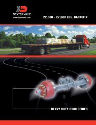
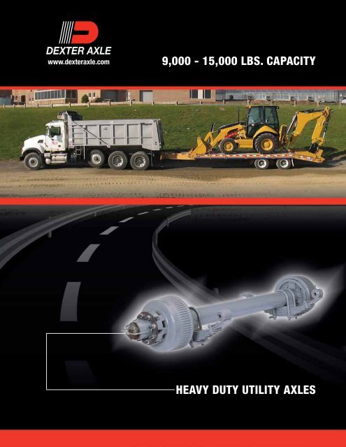
www.dexteraxle.com<br />
9,<strong>000</strong> - <strong>15</strong>,<strong>000</strong> <strong>LBS</strong>. <strong>CAPACITY</strong><br />
<strong>HEAVY</strong> <strong>DUTY</strong> <strong>UTILITY</strong> <strong>AXLES</strong>
Introduction<br />
This information is intended as a guide for the proper specification and application of Dexter Axle running gear,<br />
associated components and accessories.<br />
Dexter offers a full line of trailer axles that can be used in many different applications. When specifying any<br />
pre-engineered components such as axles, it is the responsibility of the trailer designer to insure compatibility with the<br />
vehicle and all of its sub-systems.<br />
Information<br />
The information presented is meant to assist trailer manufacturers in the specification of their running gear components.<br />
Dexter Axle does not warrant that the information given constitutes an approved trailer design or application. Dynamic<br />
loading, travel requirements unique to the trailer design, unusual service conditions, trailer configurations, unequal<br />
load distribution, hitch or coupler arrangements and towing vehicle suspension characteristics can significantly affect<br />
the performance of any trailer axle and/or suspension systems. It remains the responsibility of the trailer manufacturer<br />
to evaluate, specify and test their trailer/running gear combination before production and to certify it as such. While the<br />
information presented at the time of this writing is current, it is subject to change as designs and components evolve<br />
over time.<br />
Disclaimer of Warranty and Limitation of Liability<br />
All users of this product catalog acknowledge that the information presented is significantly affected by factors<br />
within the exclusive knowledge of the user including, among other things, service conditions, trailer configurations,<br />
load distributions, hitch and coupler arrangements and tow vehicle suspension characteristics, that the users have<br />
independently investigated these factors and have solely relied on those investigations when using this catalog, and<br />
that it is the responsibility of the user to adequately specify, evaluate and test its trailer/running gear combinations.<br />
DEXTER AXLE DISCLAIMS ALL WARRANTIES, WHETHER WRITTEN, ORAL OR IMPLIED, IN FACT OR IN<br />
LAW (INCLUDING ANY WARRANTY OF MERCHANTABILITY OR FITNESS FOR A PARTICULAR PURPOSE),<br />
ASSOCIATED WITH THE USE OF THE CATALOG AND WITH ANY INFORMATION PRESENTED BY THIS<br />
CATALOG.<br />
Dexter Axle shall not be liable in damages (whether compensatory, punitive, direct, indirect, special, incidental or<br />
consequential) to any user of this catalog under contract, tort, strict liability or any other theory of liability, and any user<br />
agrees to indemnify and hold Dexter Axle harmless from any and all claims, actions or other proceedings (including<br />
attorney fees and court costs) arising out of the use of this catalog to the extent said claims, actions or other proceedings<br />
do not arise out of the sole and exclusive negligence of Dexter Axle.<br />
Load Ratings<br />
The maximum load carrying capacity of any assembly is limited to the lowest load rating of any individual component<br />
selected. For instance, the load rating of a pair of wheels may be lower than other axle components selected. If this<br />
is the case, the load carrying capacity of the axle assembly is reduced accordingly. As a specific example, if a pair of<br />
wheels is rated at <strong>15</strong>00 pounds each and is used with other components rated at 4<strong>000</strong> pounds per axle, the maximum<br />
load capacity is limited to 3<strong>000</strong> pounds. If two tires are rated at 1400 pounds each and are used on this assembly, the<br />
maximum load carrying capacity is limited to 2800 pounds.<br />
Axle Orientation<br />
When working with trailer running gear, it is important to understand the various features and descriptions of the<br />
equipment. Most trailer axles are directional by nature, that is, it is imperative that they be installed onto the trailer in<br />
the proper manner to ensure brake functioning and correct wheel alignment. The front of the axle must be oriented<br />
toward the front of the trailer. The convention used to define right and left is based on viewing the trailer from the rear<br />
and facing in the direction of forward travel.<br />
Features to help identify the front of the axle:<br />
• Electric brake wires exit brake backing plates toward the rear of the axle.<br />
• 12¹⁄₄" hydraulic brakes have view ports through the dust shield on the back of the assembly. Where the brake<br />
lining is visible in the view port, that will indicate the rear or secondary shoe which is always oriented toward the<br />
rear of the axle.
Introduction<br />
• Slipper springs have the spring eye at the front of the axle.<br />
• Leaf spring axles with inner wiring have the wires exit the tube toward the rear of the axle.<br />
• Torflex ® axles have the wheel center trailing behind the axle tube.<br />
• Axles using ³⁄₄" spherical ball seat wheel nuts will have right and left handed threads. The right handed thread<br />
must be on the right end or curb side of the axle while the left handed thread will be on the left end or road side<br />
of the axle.<br />
Stub Axle Disclaimer<br />
A stub axle is described as a trailer axle spindle, welded to a short length of tubing. Stub axles may be specified and<br />
purchased as plain spindle/tube weldments or they may be fully assembled wheel end units, with or without trailer<br />
brakes.<br />
These incomplete axles are sold to manufacturers who wish to incorporate them into a variety of applications such<br />
as specialty vehicular axles, belt tensioning devices, machinery pivot points, etc. Dexter Axle has no control of the<br />
design intent of these special applications and therefore cannot apply a rating or capacity to these components.<br />
The spindle/tube connection has been designed for suitable stress levels when used in a trailer axle, mounted to an<br />
approved suspension system and loaded to no more than the stated capacity. The use of all or part of the product for<br />
applications other than its intended purpose may not be appropriate. It is the customers’ responsibility to determine the<br />
efficacy and safety of their particular application.<br />
Torflex ® axles can also be purchased as stub axles. This type of axle incorporates a self-contained suspension system.<br />
They can be specified as stub assemblies that will be rated for capacity when fitted with approved mounting brackets.<br />
The stated capacity will be based on the lowest rated component in each assembly.<br />
These stub assemblies are essentially half axles that are intended to be mounted to the trailer chassis independent<br />
of each other. The trailer manufacturer must assume responsibility for the integrity of the attachment as well as the<br />
final wheel alignment since independent mounting puts these critical aspects out of Dexter’s control. If used in pairs of<br />
unequal capacity, the trailer manufacturer should assign a Gross Axle Weight Rating of not more than two times the<br />
capacity of the lower rated sub assembly.
Table of Contents<br />
Required Axle Dimensions – Spring Suspensions ........................................................................................................ 4<br />
Required Axle Dimensions – Torflex ® Suspensions ....................................................................................................... 5<br />
Heavy Duty Utility Axle Beam Features ....................................................................................................................... 6<br />
Torflex ® Axle Beam Features ........................................................................................................................................ 6<br />
Torflex ® Application Information (#13)........................................................................................................................... 7<br />
9K, 10K, #13G GD Two-Piece Hub Group (after 4/13) ................................................................................................. 8<br />
9K, 10K, #13G GD One-Piece Hub Group (after 7/09) ................................................................................................ 9<br />
9K, 10K, #13G GD Two-Piece Hub Group (before 7/09) ............................................................................................... 10<br />
10,<strong>000</strong> Lb. Heavy Duty Wheel and Hub Assembly .................................................................................................... 11<br />
12,<strong>000</strong> and <strong>15</strong>,<strong>000</strong> Lb. Wheel and Hub Assembly ..................................................................................................... 12<br />
Torflex ® Application Information (#14)......................................................................................................................... 13<br />
10K, 12K, <strong>15</strong>K, #13D, and #14 Hub Groups .............................................................................................................. 14<br />
10,<strong>000</strong> & 12,<strong>000</strong> Lb. Hydraulic Disc Brake ................................................................................................................ <strong>15</strong><br />
Hydraulic Disc Brake Parts ........................................................................................................................................ <strong>15</strong><br />
Forward Self-Adjusting Electric Brake ....................................................................................................................... 16<br />
Electric Brake Parts – Stamped Backing Plate ............................................................................................................ 17<br />
Electric Brake Parts – Cast Backing Plate ................................................................................................................... 18<br />
Forward Self-Adjusting Hydraulic Brake .................................................................................................................... 19<br />
Hydraulic Brake Parts ................................................................................................................................................ 20<br />
#13G and #13D Torflex ® Hydraulic Disc Brake ........................................................................................................... 21<br />
Torflex ® Hydraulic Disc Brake Parts ............................................................................................................................ 21<br />
Electric Brake Wiring Diagram ................................................................................................................................... 22<br />
Air Brake System Diagram ........................................................................................................................................ 22<br />
“S” Cam Air Brake ...................................................................................................................................................... 23<br />
Small “S” Head Hi-Rise 28 Spline ............................................................................................................................... 23<br />
Air Brake Parts “PQ” Style .......................................................................................................................................... 24<br />
Electric – Hydraulic Brake System Diagram ............................................................................................................... 25<br />
Wheels and Tires ........................................................................................................................................................ 26<br />
Axle Overhang ............................................................................................................................................................ 26<br />
Oil Lubrication Specification ...................................................................................................................................... 27<br />
Bearing Adjustment .................................................................................................................................................... 27<br />
Axle Suspension System ........................................................................................................................................... 28<br />
Cross Frame Hanger Reinforcement ......................................................................................................................... 28<br />
Attaching Parts Suspension Kits ............................................................................................................................... 29<br />
Airflex ® for 10,<strong>000</strong> Lb. Axles ........................................................................................................................................ 32<br />
Limited Warranty ......................................................................................................................................................... 33<br />
Dexter Axle Video Gallery ........................................................................................................................................... 34<br />
3
Required Axle Dimensions<br />
Options for Spring Suspension Axles<br />
Hubface — Track Width — Spring Center<br />
Wheel Offset<br />
Axle Spacing<br />
Front Hanger<br />
Spacing<br />
Center Hanger<br />
Spacing<br />
Rear Hanger<br />
Spacing<br />
Min. Recommended<br />
Tire Clearance<br />
Frame<br />
Static Bump<br />
Clearance<br />
Tire Center<br />
Tire<br />
Radius<br />
Frame<br />
Height<br />
Ground<br />
Clearance<br />
Static Loaded<br />
Radius<br />
Overall<br />
Tire Height<br />
Front<br />
Axle<br />
Location<br />
Front Axle<br />
Spacing<br />
Rear Axle<br />
Spacing<br />
4
Required Axle Dimensions<br />
Options for Torflex ® Suspension Axles<br />
Bracket Orientation<br />
Standard<br />
Orientation<br />
Top<br />
Mount<br />
Reverse<br />
Orientation<br />
Side<br />
Mount<br />
Bracket Profile<br />
5
Dexter Heavy Duty Utility Axle Beam Features<br />
• Highest strength<br />
axle tube generally<br />
available for utility<br />
vehicle axles.<br />
• Materials used<br />
allow a stiffer and<br />
stronger axle beam<br />
with no camber<br />
required.<br />
• The backing plate of<br />
the Dexter electric<br />
or hydraulic brake<br />
mounts on piloted<br />
axle brake flange.<br />
This assures that<br />
brakes will perform<br />
effectively.<br />
Brake Flanges are machined<br />
to assure perpendicularity<br />
and concentricity.<br />
Spindles are made of<br />
forged carbon steel.<br />
High Strength Axle Tube.<br />
Spindle is friction forged<br />
onto axle tube for strength<br />
and alignment.<br />
Precision Machined<br />
Spindles. Replaceable<br />
Unitized Oil Seal.<br />
Spindle Detail<br />
Precision Machined<br />
Bearing Journals.<br />
Torflex ® Axle Beam Features<br />
#13G – General Duty #13D – Heavy Duty #14<br />
Inspected for<br />
proper alignment<br />
Dexter<br />
manufactured<br />
brakes & hubs<br />
Totally cushioned in rubber for a smooth, quiet ride<br />
Independent suspension<br />
Forged torsion arm for<br />
maximum strentgh<br />
Heat-treated<br />
solid steel bar<br />
CAUTION: Triple axle assemblies are NOT recommended for #13 or #14 Torflex ® axles.<br />
6
Torflex ® Application Information<br />
9,<strong>000</strong> -10,<strong>000</strong> Lbs.<br />
13<br />
Articulation Dimensions<br />
Dimensions are for high profile, top mount<br />
only. Side mount is .31" higher. Allow 3" bump<br />
clearance from full load.<br />
Start Angle<br />
Bracket<br />
Profile<br />
No Load Full Load Shock Load<br />
H L H L H L<br />
45° Down High 7.18 4.24 5.24 5.54 4.24 5.83<br />
<br />
32° Down High 6.12 5.09 3.93 5.92 2.94 5.84<br />
<br />
22.5° Down High 5.24 5.54 2.94 6.00 1.90 5.91<br />
10° Down High 3.98 5.91 1.64 5.86 0.64 5.54<br />
0° High 2.94 6.00 0.64 5.54 -0.28 5.06<br />
10° Up High 1.90 5.91 -0.28 5.06 -0.11 4.42<br />
22.5° Up High 0.64 5.54 -1.30 4.24 -1.97 3.44<br />
Overhang Per Side<br />
Spindle Min. Max. Brake<br />
#13D 12.25" 17.20" 12¹⁄₄" x 4"<br />
#13G one-piece 10.11" 17.20" 12¹⁄₄" x 3³⁄₈"<br />
#13G two-piece 11.35" 17.20" 12¹⁄₄" x 3³⁄₈"<br />
Note: Positive numbers in the H column indicate the<br />
spindle is BELOW the top of the bracket. Conversely,<br />
negative numbers are ABOVE the top of the bracket.<br />
Note: Dual wheel not available for #13G one-piece.<br />
One-piece hub/drum is not interchangeable with the<br />
two-piece hub & drum.<br />
<br />
13<br />
Full Load Dimensions<br />
Dimensions are for high profile, top mount only. Side mount is .31" higher. Allow 3" bump clearance from full load.<br />
C<br />
H<br />
E<br />
C<br />
H<br />
E<br />
C<br />
H<br />
E<br />
B<br />
D<br />
B<br />
D<br />
B<br />
D<br />
0º, 10º down 10º, 22.5º up 22.5º, 32º, 45º down<br />
Start Angle<br />
* * * 45° Down 32° Down 22.5° Down 10° Down 0° 10° Up 22.5° Up<br />
Tire D E H B C H B C H B C H B C H B C H B C H B C<br />
LT235/85R16 14.3 <strong>15</strong>.4 5.2 19.5 10.2 3.9 18.2 11.4 2.9 17.2 12.5 1.6 <strong>15</strong>.9 13.8 .6 14.9 14.8 -0.3 14.0 <strong>15</strong>.7 -1.3 13.0 16.7<br />
2<strong>15</strong>/75R17.5 14.0 <strong>15</strong>.3 5.2 19.2 10.1 3.9 17.9 11.3 2.9 16.9 12.4 1.6 <strong>15</strong>.6 13.7 .6 14.6 14.7 -0.3 13.7 <strong>15</strong>.6 -1.3 12.7 16.6<br />
235/75R17.5 14.3 <strong>15</strong>.7 5.2 19.5 10.5 3.9 18.2 11.7 2.9 17.2 12.8 1.6 <strong>15</strong>.9 14.1 .6 14.9 <strong>15</strong>.1 -0.3 14.0 16.0 -1.3 13.0 17.0<br />
9R17.5HC <strong>15</strong>.4 17.1 5.2 20.6 11.9 3.9 19.3 13.1 2.9 18.3 14.2 1.6 17.0 <strong>15</strong>.5 .6 16.0 16.5 -0.3 <strong>15</strong>.1 17.4 -1.3 14.1 18.4<br />
10R17.5HC <strong>15</strong>.6 18.0 5.2 20.8 12.8 3.9 19.5 14.0 2.9 18.5 <strong>15</strong>.1 1.6 17.2 16.4 .6 16.2 17.4 -0.3 <strong>15</strong>.3 18.3 -1.3 14.3 19.3<br />
Columns D and E are dimensional examples only:<br />
* D – Static Loaded Radius<br />
** E – Inflated Radius<br />
#13D & #13G<br />
Bracket Dimensions<br />
A 1.22<br />
B 3.63<br />
C 10.56<br />
D 10.56<br />
E 13.00<br />
F 5.50<br />
G 2.50<br />
H 2.25<br />
I 7.26<br />
J 1.00<br />
K 1.00<br />
Bolt Size ⁵⁄₈" bolt<br />
Tube Size 3.88<br />
K<br />
E<br />
D<br />
1/2 G<br />
F<br />
A<br />
C<br />
I<br />
High Profile<br />
B<br />
J G<br />
H<br />
A<br />
For Wiring<br />
Access<br />
Bolt Size<br />
Side Mount Hanger<br />
7
9K, 10K, and #13G General Duty Two-Piece Hub Group<br />
After April 2013<br />
16 <strong>15</strong><br />
20<br />
23<br />
1 2 3<br />
22 4 5 7 6 8 6 10 9 12<br />
22A<br />
13<br />
14<br />
24<br />
21<br />
25 26<br />
27<br />
9-10K_13G_Hubs_2pc_>4-13_7-13<br />
17<br />
19<br />
18<br />
Standard Oil Lube Parts<br />
Item Part No. Description<br />
1 010-051-00 Oil Seal<br />
2 031-019-02 387A Inner Bearing Cone<br />
3 031-019-01 382A Inner Bearing Cup<br />
4 031-030-01 25520 Outer Bearing Cup<br />
5 031-030-02 25580 Outer Bearing Cone<br />
6 006-096-00 Spindle Nut (2)<br />
7 005-070-00 Spindle Washer<br />
8 005-071-00 Tang Washer<br />
9 021-088-00 Oil Cap<br />
10 010-163-00 ‘O’ Ring<br />
12 046-032-00 Oil Cap Plug<br />
13 007-1<strong>15</strong>-00 ⁵⁄₈-18 Wheel Stud<br />
14 007-292-00 Drum Mounting Screw<br />
<strong>15</strong> 007-116-00 Brake Mounting Bolt<br />
16 006-017-00 Brake Mounting Nut<br />
ns 005-008-00 Lockwasher<br />
Hub & Drum<br />
Item Part No. Description<br />
ns 008-430-05 Oil Hub and Drum w/Cups and Studs<br />
22 008-430-03 Oil Hub w/Cups and Studs<br />
23 009-123-01 Drum - Machined<br />
ns 008-430-07 Oil Hub and Drum w/Cups and Studs ABS<br />
22 008-430-03 Oil Hub w/Cups and Studs<br />
ns 009-123-03 Drum - for ABS<br />
ns - not shown<br />
12¹⁄₄" x 3³⁄₈" Brakes<br />
Item Part No. Description<br />
20 K23-450-00/K23-451-00 LH/RH Electric, FSA<br />
21 K23-410-00/K23-411-00 LH/RH Hydraulic, FSA, Duo-Servo<br />
21 K23-210-00/K23-211-00 LH/RH Hydraulic, RSA, Du-Servo w/Park<br />
ns K23-412-00/K23-413-00 LH/RH Hydraulic, FSA, Single-Servo<br />
ns K23-234-00/K23-235-00 LH/RH Hydraulic, Manual Adjust<br />
Single-Servo w/Park<br />
ABS Components<br />
Item Part No. Description<br />
24 097-004-00 Sensor, Straight<br />
25 024-204-00 Sensor Block<br />
26 097-002-00 Sensor Clip<br />
27 024-205-01 Tone Ring<br />
ns 007-248-00 Tone Ring Screws<br />
Studs and Wheel Nuts<br />
Item Part No. Description Nut Torque<br />
18* 006-109-00 ⁵⁄₈-18 90° Cone Nut 200 lbs.-ft<br />
19* 033-052-01 Clamp Ring<br />
17 006-058-00 ⁵⁄₈-18 Flange Nut 300 lbs.-ft<br />
13 007-1<strong>15</strong>-00 ⁵⁄₈-18 Press-in Stud<br />
* Must use the 90° cone nut with the clamp ring. Alternate fastener is just the<br />
flange nut.<br />
8
9K, 10K, and #13G General Duty One-Piece Hub Group<br />
After July 2009<br />
<strong>15</strong> 14<br />
20<br />
23<br />
1 2 3<br />
4 5 7 6 8 6 10 9 12<br />
9-10K_13G_Hubs_1pc_4-09<br />
13<br />
17<br />
18<br />
29<br />
26<br />
21<br />
27 28<br />
Note: Dual wheel cannot be used with #13G<br />
19<br />
Standard Oil Lube Parts<br />
Item Part No. Description<br />
1 010-051-00 Oil Seal<br />
2 031-019-02 387A Inner Bearing Cone<br />
3 031-019-01 382A Inner Bearing Cup<br />
4 031-030-01 25520 Outer Bearing Cup<br />
5 031-030-02 25580 Outer Bearing Cone<br />
6 006-096-00 Spindle Nut (2)<br />
7 005-070-00 Spindle Washer<br />
8 005-071-00 Tang Washer<br />
9 021-088-00 Oil Cap<br />
10 010-163-00 ‘O’ Ring<br />
12 046-032-00 Oil Cap Plug<br />
13 007-1<strong>15</strong>-00 ⁵⁄₈-18 Wheel Stud<br />
14 007-116-00 Brake Mounting Bolt<br />
<strong>15</strong> 006-017-00 Brake Mounting Nut<br />
ns 005-008-00 Lockwasher<br />
Hub & Drum<br />
Item Part No. Description<br />
23 008-4<strong>15</strong>-02 Hub & Drum Assembly<br />
ns 008-4<strong>15</strong>-04 Hub & Drum Assembly - ABS<br />
ns - not shown<br />
12¹⁄₄" x 3³⁄₈" Brakes<br />
Item Part No. Description<br />
20 K23-450-00/K23-451-00 LH/RH Electric, FSA<br />
21 K23-410-00/K23-411-00 LH/RH Hydraulic, FSA, Duo-Servo<br />
21 K23-210-00/K23-211-00 LH/RH Hydraulic, RSA, Du-Servo w/Park<br />
ns K23-412-00/K23-413-00 LH/RH Hydraulic, FSA, Single-Servo<br />
ns K23-234-00/K23-235-00 LH/RH Hydraulic, Manual Adjust<br />
Single-Servo w/Park<br />
ABS Components<br />
Item Part No. Description<br />
26 097-004-00 Sensor, Straight<br />
27 024-204-00 Sensor Block<br />
28 097-002-00 Sensor Clip<br />
29 024-205-01 Tone Ring<br />
ns 007-248-00 Tone Ring Screws<br />
Studs and Wheel Nuts<br />
Item Part No. Description Nut Torque<br />
18* 006-109-00 ⁵⁄₈-18 90° Cone Nut 200 lbs.-ft<br />
19* 033-052-01 Clamp Ring<br />
17 006-058-00 ⁵⁄₈-18 Flange Nut 300 lbs.-ft<br />
13 007-1<strong>15</strong>-00 ⁵⁄₈-18 Press-in Stud<br />
* Must use the 90° cone nut with the clamp ring. Alternate fastener is just the<br />
flange nut.<br />
9
9K, 10K, #13G, #14T General Duty Two-Piece Hub Group<br />
Before July 2009<br />
16 <strong>15</strong><br />
20<br />
23<br />
1 2 3<br />
22 4 5 7 6 8 6 10 9 12<br />
22A<br />
13<br />
14<br />
23A<br />
24<br />
21<br />
25 26<br />
27<br />
28<br />
29<br />
9-10K_13G_Hubs_2pc_4-10<br />
17<br />
19<br />
18<br />
Standard Oil Lube Parts<br />
Item Part No. Description<br />
1 010-051-00 Oil Seal<br />
2 031-019-02 387A Inner Bearing Cone<br />
3 031-019-01 382A Inner Bearing Cup<br />
4 031-030-01 25520 Outer Bearing Cup<br />
5 031-030-02 25580 Outer Bearing Cone<br />
6 006-096-00 Spindle Nut (2)<br />
7 005-070-00 Spindle Washer<br />
8 005-071-00 Tang Washer<br />
9 021-036-00 Oil Cap<br />
10 010-050-00 ‘O’ Ring<br />
12 046-032-00 Oil Cap Plug<br />
13 007-1<strong>15</strong>-00 ⁵⁄₈-18 Wheel Stud<br />
14 007-245-00 Drum Mounting Screw<br />
<strong>15</strong> 007-116-00 Brake Mounting Bolt<br />
16 006-017-00 Brake Mounting Nut<br />
ns 005-008-00 Lockwasher<br />
Hub & Drum<br />
Item Part No. Description<br />
22 008-288-03 Oil Hub w/Cups and Studs<br />
23 009-044-01 Drum - Machined<br />
ns 009-044-03 Drum - for ABS<br />
ns 008-288-05 Oil Hub and Drum w/Cups and Studs<br />
Hub & Rotor<br />
Available on #13G – Not Offered on D90, D100G, #14T<br />
Item Part No. Description<br />
22A 008-288-07 Oil Hub w/Cups and Studs<br />
23A 070-006-01 Brake Rotor<br />
28 006-046-00 Rotor Mounting Nut<br />
29 025-014-00 Rotor Mounting Stud<br />
12¹⁄₄" x 3³⁄₈" Brakes<br />
Item Part No. Description<br />
20 K23-450-00/K23-451-00 LH/RH Electric, FSA<br />
21 K23-410-00/K23-411-00 LH/RH Hydraulic, FSA, Duo-Servo<br />
21 K23-210-00/K23-211-00 LH/RH Hydraulic, RSA, Du-Servo w/Park<br />
ns K23-412-00/K23-413-00 LH/RH Hydraulic, FSA, Single-Servo<br />
ns K23-234-00/K23-235-00 LH/RH Hydraulic, Manual Adjust<br />
Single-Servo w/Park<br />
ABS Components<br />
Item Part No. Description<br />
24 097-004-00 Sensor, Straight<br />
25 024-204-00 Sensor Block<br />
26 097-002-00 Sensor Clip<br />
27 024-203-00 Tone Ring<br />
Studs and Wheel Nuts<br />
Item Part No. Description Nut Torque<br />
18* 006-109-00 ⁵⁄₈-18 90° Cone Nut 200 lbs.-ft<br />
19* 033-052-01 Clamp Ring<br />
17 006-058-00 ⁵⁄₈-18 Flange Nut 300 lbs.-ft<br />
13 007-1<strong>15</strong>-00 ⁵⁄₈-18 Press-in Stud<br />
ns - not shown<br />
* Must use the 90° cone nut with the clamp ring. Alternate fastener is just the<br />
flange nut.<br />
One-piece hub/drum is not interchangeable with the two-piece hub & drum.<br />
10
10,<strong>000</strong> Lb. Heavy Duty Wheel & Hub Assembly<br />
Unitized Seal<br />
Seals internally within<br />
the seal, with two sealing<br />
lips and press fitted to<br />
the spindle for improved<br />
performance.<br />
Tapered roller bearings<br />
Computer matched to Dexter Axle system<br />
Outer: 031-019-01 (382A) cup, 031-019-02 (387A) cone<br />
Inner: 031-022-01 (394A) cup, 031-022-02 (395S) cone<br />
10kassy_4-12.ai<br />
Hardened spindle washer.<br />
12¼" x 4" high<br />
performance hydraulic<br />
brake. Electric and air<br />
brake, parking<br />
feature and<br />
uni-servo<br />
hydraulic brakes<br />
are also available.<br />
Bearing adjustment nuts<br />
with tang locking washer keyed<br />
to spindle to maintain precision<br />
bearing adjustment.<br />
Removable rubber<br />
oil filler plug for ease<br />
of maintenance.<br />
Transparent<br />
polycarbonate<br />
oil cap with oil level<br />
indicator mark to allow<br />
visual checking for<br />
adequate lubricant.<br />
Two piece hub & drum design<br />
permits replacement of brake drum<br />
without the need to replace hub.<br />
Cast brake drum with integral brake<br />
armature. Alloy selected for both brake<br />
energy (heat) absorption and good<br />
magnetic braking characteristics.<br />
Finned outer surfaces in braking<br />
area for maximum cooling.<br />
Dual and single wheel design<br />
Axle designed for oil bath<br />
lubrication of bearings with<br />
SAE 80W-90 hypoid gear<br />
oil. This lubrication method<br />
assures long bearing life with<br />
proper maintenance of oil<br />
level.<br />
When using clamp ring and 90°<br />
cone nuts, tighten wheel nuts to<br />
a torque of 200 Ft. Lbs.<br />
Cast hub with precision<br />
machined bearing and<br />
wheel mounting surfaces.<br />
11
12,<strong>000</strong> Lb. Wheel & Hub Assembly<br />
Unitized Seal<br />
Seals internally within the seal,<br />
with two sealing lips and press<br />
fitted to the spindle for<br />
improved performance.<br />
Tapered roller bearings<br />
Computer matched to Dexter Axle system.<br />
Outer: 031-021-01 (28622) cup<br />
031-021-02 (28682) cone<br />
Inner: 031-020-01 (3920) cup<br />
031-020-02 (3984) cone<br />
*12K Low profile hub is<br />
available for use with 14.5"<br />
diameter dual wheels.<br />
Tighten wheel nuts to a<br />
torque of 200 Ft. Lbs.<br />
Hardened spindle<br />
washer.<br />
12kassy_4-12.ai<br />
12¼" x 5" high<br />
performance<br />
hydraulic brake. Electric<br />
and air brake,<br />
parking feature<br />
and uni-servo<br />
hydraulic brakes are<br />
also available.<br />
Bearing adjustment nuts<br />
with tang locking washer<br />
keyed to spindle to maintain<br />
precision bearing adjustment.<br />
Removable rubber<br />
oil filler plug for ease<br />
of maintenance.<br />
Transparent poly-carbonate<br />
oil cap with oil level indicator<br />
mark to allow visual checking<br />
for adequate lubricant.<br />
Two piece hub and drum design<br />
permits replacement of brake drum without<br />
the need to replace hub. Cast brake drum<br />
with integral brake armature. Alloy selected<br />
for both brake energy (heat) absorption and<br />
good magnetic braking characteristics.<br />
Finned outer surfaces in braking area for<br />
maximum cooling.<br />
Axle designed for oil bath lubrication<br />
of bearings with SAE 80W-90 hypoid<br />
gear oil. This lubrication method<br />
assures long bearing life with proper<br />
maintenance of oil level.<br />
<strong>15</strong>,<strong>000</strong> Lb. Wheel & Hub Assembly<br />
Cast hub with precision<br />
machined bearing and<br />
wheel mounting surface.<br />
*Note: 12K Hi profile hub is available<br />
for use with 16" and 16.5" diameter<br />
dual wheels and tires, or 17.5" diameter<br />
single wheel and tire.<br />
Unitized Seal<br />
Seals internally within the<br />
seal, with two sealing lips<br />
and press fitted to the<br />
spindle for improved<br />
performance.<br />
Tighten wheel nuts to a<br />
torque of 450-500 Ft. Lbs.<br />
Tapered roller bearings<br />
Computer matched to Dexter Axle system.<br />
Outer: 031-021-01 (28622) cup<br />
031-021-02 (28682) cone<br />
Inner: 031-020-01 (3920) cup<br />
031-020-02 (3984) cone<br />
Hardened spindle washer.<br />
<strong>15</strong>kassy_4-12.ai<br />
Bearing adjustment nuts<br />
with tang locking washer<br />
keyed to spindle to maintain<br />
precision bearing adjustment.<br />
12¼" x 5" high<br />
performance<br />
hydraulic brake.<br />
Electric, air brake,<br />
parking feature, and<br />
ABS brakes are<br />
also available.<br />
Removable rubber<br />
oil filler plug for ease<br />
of maintenance.<br />
Transparent poly-carbonate<br />
oil cap with oil level<br />
indicator mark to allow<br />
visual checking for<br />
adequate lubricant.<br />
Cast hub with<br />
precision machined<br />
bearing and wheel<br />
mounting surface.<br />
12<br />
Axle designed for oil bath lubrication of<br />
bearings with SAE 80W-90 hypoid gear oil.<br />
This lubrication method assures long bearing<br />
life with proper maintenance of oil level.
Torflex ® Application Information<br />
12,<strong>000</strong> Lbs.<br />
14<br />
Articulation Dimensions<br />
Dimensions are for #14 bracket. Allow 3" bump<br />
clearance from full load.<br />
Start Angle<br />
Bracket<br />
Profile<br />
No Load Full Load Shock Load<br />
H L H L H L<br />
45° Down High 7.68 4.24 5.74 5.54 4.74 5.83<br />
H<br />
32° Down High 6.62 5.09 4.43 5.92 3.44 5.84<br />
22.5° Down High 5.74 5.54 3.44 6.00 2.40 5.91<br />
10° Down High 4.48 5.91 2.14 5.86 1.14 5.54<br />
0° High 3.44 6.00 1.14 5.54 0.22 5.06<br />
10° Up High 2.40 5.91 0.22 5.06 0.39 4.42<br />
22.5° Up High 1.14 5.54 -0.80 4.24 -1.47 3.44<br />
Overhang Per Side<br />
Spindle Min. Brake<br />
#14 12.75" 12¹⁄₄" x 5"<br />
#14T 9.89" 12¹⁄₄" x 3³⁄₈"<br />
#14 9.19" Disc<br />
Note: Positive numbers in the H column indicate the<br />
spindle is BELOW the top of the bracket. Conversely,<br />
negative numbers are ABOVE the top of the bracket.<br />
Note: One-piece hub/drum is not interchangeable with<br />
the two-piece hub & drum.<br />
L<br />
14<br />
Full Load Dimensions<br />
C<br />
H<br />
E<br />
C<br />
H<br />
E<br />
C<br />
H<br />
E<br />
B<br />
D<br />
B<br />
D<br />
B<br />
D<br />
0º, 10º down 10º, 22.5º up 22.5º, 32º, 45º down<br />
Start Angle<br />
* * * 45° Down 32° Down 22.5° Down 10° Down 0° 10° Up 22.5° Up<br />
Tire D E H B C H B C H B C H B C H B C H B C H B C<br />
LT235/85R16 14.3 <strong>15</strong>.4 5.7 20.0 9.70 4.4 18.7 11.0 3.4 17.7 12.0 2.1 16.4 13.3 1.1 <strong>15</strong>.4 14.3 .2 14.5 <strong>15</strong>.2 -0.8 13.5 16.2<br />
2<strong>15</strong>/75R17.5 14.0 <strong>15</strong>.3 5.7 19.7 9.60 4.4 18.4 10.9 3.4 17.4 11.9 2.1 16.1 13.2 1.1 <strong>15</strong>.1 14.2 .2 14.2 <strong>15</strong>.1 -0.8 13.2 16.1<br />
235/75R17.5 14.3 <strong>15</strong>.7 5.7 20.0 10.0 4.4 18.7 11.3 3.4 17.7 12.3 2.1 16.4 13.6 1.1 <strong>15</strong>.4 14.6 .2 14.5 <strong>15</strong>.5 -0.8 13.5 16.5<br />
9R17.5HC <strong>15</strong>.4 17.1 5.7 21.1 11.4 4.4 19.8 12.7 3.4 18.8 13.7 2.1 17.5 <strong>15</strong>.0 1.1 16.5 16.0 .2 <strong>15</strong>.6 16.9 -0.8 14.6 17.9<br />
10R17.5HC <strong>15</strong>.6 18.0 5.7 21.3 12.3 4.4 20.0 13.6 3.4 19.0 14.6 2.1 17.7 <strong>15</strong>.9 1.1 16.7 16.9 .2 <strong>15</strong>.8 17.8 -0.8 14.8 18.8<br />
Columns D and E are dimensional examples only:<br />
* D – Static Loaded Radius<br />
** E – Inflated Radius<br />
C<br />
B<br />
#14<br />
Bracket Dimensions<br />
A 4.50<br />
B 9.00<br />
C 12.00<br />
D 4.50<br />
E 2.44<br />
F 2.50<br />
Bolt Size ³⁄₄" bolt<br />
Tube Size 4.25<br />
F<br />
D<br />
A<br />
E<br />
Bolt Size<br />
High Profile<br />
13
10K, 12K, <strong>15</strong>K, #13D, and #14 Hub Groups<br />
1 2 3 4<br />
5<br />
6<br />
7<br />
8 9 10 11 12 11 13 14 <strong>15</strong><br />
21<br />
23<br />
10-<strong>15</strong>hub_11-08<br />
5A<br />
22<br />
16<br />
17<br />
16<br />
Item<br />
Description<br />
10K, #13D<br />
8 on 6.50<br />
10K, #13D<br />
Disc<br />
8 on 6.50<br />
12K<br />
Low-Profile<br />
8 on 6.50<br />
12K<br />
Hi-Profile<br />
8 on 6.50<br />
#14<br />
Hi-Profile<br />
8 on 6.50<br />
12K<br />
Disc<br />
8 on 6.50<br />
<strong>15</strong>K<br />
8 on 275 mm<br />
2 Unitized Oil Seal 010-056-00 010-056-00 010-056-00 010-056-00 010-056-00 010-056-00 010-056-00<br />
3 Inner Bearing Cone 031-022-02<br />
(395S)<br />
4 Inner Bearing Cup 031-022-01<br />
(394A)<br />
031-022-02<br />
(395S)<br />
031-022-01<br />
(394A)<br />
031-020-02<br />
(3984)<br />
031-020-01<br />
(3920)<br />
031-020-02<br />
(3984)<br />
031-020-01<br />
(3920)<br />
031-020-02<br />
(3984)<br />
031-020-01<br />
(3920)<br />
031-020-02<br />
(3984)<br />
031-020-01<br />
(3920)<br />
031-020-02<br />
(3984)<br />
031-020-01<br />
(3920)<br />
5 Brake Drum 009-027-01 – 009-028-01 009-028-01 009-028-01 – 009-028-01<br />
5 Brake Drum-ABS 009-027-03 – 009-028-05 009-028-05 009-028-05 – 009-028-05<br />
5A Brake Rotor – 070-006-01 – – – 070-006-01 –<br />
5A Brake Rotor-ABS – 070-006-02 – – – 070-006-02 –<br />
6 Wheel Mounting Stud 007-1<strong>15</strong>-00<br />
–<br />
7 Hubs w/Cups & Studs 008-214-05<br />
–<br />
8 Outer Bearing Cup 031-019-01<br />
(382A)<br />
9 Outer Bearing Cone 031-019-02<br />
(387A)<br />
007-1<strong>15</strong>-00<br />
–<br />
008-214-06<br />
–<br />
031-019-01<br />
(382A)<br />
031-019-02<br />
(387A)<br />
007-1<strong>15</strong>-00<br />
–<br />
008-216-08<br />
–<br />
031-021-01<br />
(28622)<br />
031-021-02<br />
(28682)<br />
007-1<strong>15</strong>-00<br />
–<br />
008-214-08<br />
–<br />
031-021-01<br />
(28622)<br />
031-021-02<br />
(28682)<br />
007-1<strong>15</strong>-00<br />
–<br />
008-422-03<br />
–<br />
031-021-01<br />
(28622)<br />
031-021-02<br />
(28682)<br />
007-1<strong>15</strong>-00<br />
–<br />
008-214-10<br />
–<br />
031-021-01<br />
(28622)<br />
031-021-02<br />
(28682)<br />
007-194-00<br />
(std)<br />
007-195-00<br />
(long)<br />
008-401-05<br />
(std stud)<br />
008-401-06<br />
(long stud)<br />
031-021-01<br />
(28622)<br />
031-021-02<br />
(28682)<br />
10 Spindle Washer 005-060-00 005-060-00 005-060-00 005-060-00 005-060-00 005-060-00 005-060-00<br />
11 Spindle Nut 006-084-00 006-084-00 006-084-00 006-084-00 006-084-00 006-084-00 006-084-00<br />
12 Tang Washer 005-059-00 005-059-00 005-059-00 005-059-00 005-059-00 005-059-00 005-059-00<br />
13 Oil Cap "O" Ring 010-050-00 010-050-00 010-050-00 010-050-00 010-050-00 010-050-00 010-050-00<br />
14 Oil Cap 021-036-00 021-036-00 021-036-00 021-036-00 021-036-00 021-036-00 021-036-00<br />
<strong>15</strong> Oil Cap Plug 046-032-00 046-032-00 046-032-00 046-032-00 046-032-00 046-032-00 046-032-00<br />
16 Wheel Clamp Ring<br />
Wheel Nut<br />
033-052-01<br />
006-109-00<br />
033-052-01<br />
006-109-00<br />
033-052-01<br />
006-109-00<br />
033-052-01<br />
006-109-00<br />
033-052-01<br />
006-109-00<br />
033-052-01<br />
006-109-00<br />
17 Flange Nut (swivel) – – – – – – 006-118-00<br />
21 Drum Mounting Screw 007-244-00 – 007-244-00 007-244-00 007-245-00 – 007-244-00<br />
22 Rotor Mounting Stud – 025-014-00 – – – 025-014-00 –<br />
23 Rotor Mounting Nut – 006-046-00 – – – 006-046-00 –<br />
–<br />
–<br />
14
10,<strong>000</strong> and 12,<strong>000</strong> Lb. Hydraulic Disc Brake<br />
Caliper Pistons (underneath<br />
housing) are larger, for greater<br />
brake torque. Dual Pistons per<br />
caliper.<br />
Corrosion-Resistant Bolts.<br />
Universal Caliper and Universal<br />
Brake Pads eliminate the need<br />
to stock right-hand and left-hand<br />
parts.<br />
Brake Shoes of heavy steel are bonded to<br />
brake linings for extended lining life. Linings are<br />
truck type for improved stopping force and<br />
extended service life.<br />
Two-Piece Hub and Rotor Design allows<br />
rotor replacement without requiring new<br />
hub.<br />
Dexter Ventilated Disc Rotors. High<br />
grade alloy iron to prevent heat<br />
checking and distortion. Ventilation<br />
provides great heat dissipation.<br />
Hydraulic Disc Brake Parts<br />
Item Description Qty/Brake 10K, 12K #14<br />
1 Anchor Yoke Assembly<br />
(includes 6 of item #6)<br />
2 Caliper Assembly<br />
(includes items #6, 3, 9, 10)<br />
1 090-002-02 090-011-02<br />
1 089-002-02 089-002-02<br />
3 Caliper Piston 2 054-066-00 054-066-00<br />
12 Shoulder Screw ⁵⁄₈ x 5 2 007-186-00 007-186-00<br />
13 Hex Screw ⁷⁄₁₆-20 x 1.75 7 007-116-00 007-116-00<br />
14 Flange Nut 8 006-046-00 –<br />
<strong>15</strong> Hex Nut ⁷⁄₁₆-20 7 006-017-00 006-017-00<br />
16 Rotor Mounting Stud 8 025-014-00 –<br />
17 ABS Sensor (straight) 1 097-004-00 –<br />
19 ABS Sensor Retaining Clip 1 097-002-00 –<br />
20 ABS Tone Ring 1 024-203-00 –<br />
21 Lock Washer 7 005-008-00 –<br />
Caliper Repair Kit Contains: 1 K71-181-00 K71-181-00<br />
6<br />
7<br />
9<br />
10<br />
"O" Ring<br />
Bleeder Screw<br />
Caliper Seal<br />
Dust Boot<br />
4<br />
1<br />
2<br />
2<br />
010-062-00<br />
054-069-00<br />
054-067-00<br />
054-068-00<br />
010-062-00<br />
054-069-00<br />
054-067-00<br />
054-068-00<br />
Disc Brake Replacement Pad Kit Contains: 1 K71-180-00 K71-180-00<br />
4<br />
5<br />
6<br />
8<br />
11<br />
Brake Pad<br />
Anti-Rattle Spring<br />
"O" Ring<br />
Hex Locknut<br />
Installation Tool<br />
4<br />
4<br />
20<br />
4<br />
1<br />
091-003-00<br />
046-105-00<br />
010-062-00<br />
006-125-00<br />
071-182-00<br />
091-003-00<br />
046-105-00<br />
010-062-00<br />
006-125-00<br />
071-182-00<br />
8<br />
7<br />
17<br />
2 3<br />
6 4 5 6<br />
11<br />
9<br />
10<br />
6<br />
14<br />
6<br />
6<br />
6<br />
19 20<br />
13<br />
<strong>15</strong><br />
1<br />
21Hyddisc_6-11<br />
12<br />
16<br />
Recommend hose with banjo fiting.<br />
⁷⁄₁₆-20 threaded hole for fitting.<br />
<strong>15</strong>
Forward Self-Adjusting Electric Brake<br />
Anchor post of high strength<br />
steel to accept high torques of<br />
heavy duty brake service.<br />
Backing Plate is a cast spider from<br />
high strength ductile iron designed<br />
for long life under heavy duty<br />
braking conditions.<br />
Adjuster Spring holds heel ends<br />
of brake shoes engaged with<br />
adjuster link.<br />
Heavy Duty Actuating<br />
Lever with oil impregnated<br />
bushing for long trouble-free<br />
operation.<br />
Adjuster Link transmits braking forces<br />
between brake shoes. Length is adjusted<br />
during normal vehicle forward and reverse<br />
operation to maintain close brakes<br />
shoe-to-drum relation for maximum braking<br />
efficiency and service-free operation.<br />
Adjuster Pawl is cable actuated when<br />
brake is applied while vehicle is<br />
operating in forward or reverse.<br />
Brake Linings are truck type for<br />
improved stopping force and extended<br />
service life. Linings are bonded to<br />
brake shoes for more useable<br />
lining life.<br />
Electromagnet, powdered metal body with large,<br />
friction wear surface. Spring on actuating lever<br />
pin positions electromagnet positively against<br />
drum armature surface.<br />
Brake Shoes are fabricated out of heavy gauge<br />
steel to completely support brake linings under<br />
service conditions without warping. The shoes<br />
assure adequate strength to withstand high<br />
forces needed for more efficient braking.<br />
Electric Brakes<br />
Size Capacity Part No. LH Part No. RH<br />
12¹⁄₄" x 3³⁄₈" 9K, 10K GD, #13G K23-450-00 K23-451-00<br />
12¹⁄₄" x 4" 10K, #13D K23-438-00 K23-439-00<br />
12¹⁄₄" x 5" 12K K23-442-00 K23-443-00<br />
12¹⁄₄" x 5" <strong>15</strong>K K23-446-00 K23-447-00<br />
16
Electric Brake Parts – Stamped Backing Plate Prior to April 2<strong>000</strong><br />
Service Parts Only<br />
19 2<br />
12x3e_stamped_5-11<br />
3<br />
4<br />
1<br />
1 5<br />
7<br />
26 27<br />
11<br />
16<br />
17<br />
21<br />
8 9<br />
13<br />
1<br />
20<br />
<strong>15</strong><br />
14<br />
6<br />
9<br />
12<br />
Item Description Qty Per Brake<br />
1 LH Shoe & Lining Kit Contains:<br />
LH Primary<br />
LH Secondary<br />
Shoe Hold Down Washer<br />
Lock Nut<br />
1 RH Shoe & Lining Kit Contains:<br />
RH Primary<br />
RH Secondary<br />
Shoe Hold Down Washer<br />
Lock Nut<br />
1<br />
1<br />
1<br />
2<br />
2<br />
1<br />
1<br />
1<br />
2<br />
2<br />
12¹⁄₄" x 3³⁄₈"<br />
9K, 10K GD, #13G<br />
Part No.<br />
K71-049-00<br />
040-110-01<br />
040-111-02<br />
005-107-00<br />
006-127-00<br />
K71-050-00<br />
040-111-01<br />
040-110-02<br />
005-107-00<br />
006-127-00<br />
12¹⁄₄" x 4"<br />
10K, #13D<br />
Part No.<br />
K71-051-00<br />
040-108-01<br />
040-109-02<br />
005-107-00<br />
006-127-00<br />
K71-052-00<br />
040-109-01<br />
040-108-02<br />
005-107-00<br />
006-127-00<br />
12¹⁄₄" x 5"<br />
12K<br />
Part No.<br />
K71-053-00<br />
040-102-01<br />
040-103-02<br />
005-107-00<br />
006-127-00<br />
K71-054-00<br />
040-103-01<br />
040-102-02<br />
005-107-00<br />
006-127-00<br />
12¹⁄₄" x 5"<br />
<strong>15</strong>K<br />
Part No.<br />
K71-053-00<br />
040-102-01<br />
040-103-02<br />
005-107-00<br />
006-127-00<br />
K71-054-00<br />
040-103-01<br />
040-102-02<br />
005-107-00<br />
006-127-00<br />
2 Backing Plate Assembly (obsolete) 1 036-072-05 036-072-05 036-072-06 036-072-06<br />
3 Shoe Return Spring (rear-black) 1 046-071-00 046-071-00 046-071-00 046-071-00<br />
4 Shoe Return Spring (front-green) 1 046-083-00 046-083-00 046-083-00 046-083-00<br />
5 LH Actuator Arm Assembly<br />
RH Actuator Arm Assembly<br />
1<br />
1<br />
047-123-38<br />
047-123-37<br />
047-123-38<br />
047-123-37<br />
047-123-36<br />
047-123-35<br />
047-123-36<br />
047-123-35<br />
6 Wire Clip 3 027-039-00 027-039-00 027-039-00 027-039-00<br />
7 LH Arm/Shoe Retainer<br />
RH Arm/Shoe Retainer<br />
1<br />
1<br />
071-455-01<br />
071-455-02<br />
071-455-01<br />
071-455-02<br />
071-455-01<br />
071-455-02<br />
071-455-01<br />
071-455-02<br />
8 Flange Nut 1 006-092-01 006-092-01 006-092-01 006-092-01<br />
9 Magnet Kit Contains:<br />
Magnet Retainer Clip<br />
Magnet Assembly<br />
Magnet Mounting Spring<br />
1<br />
1<br />
1<br />
1<br />
K71-376-00<br />
027-050-00<br />
042-129-00<br />
046-117-00<br />
K71-376-00<br />
027-050-00<br />
042-129-00<br />
046-117-00<br />
K71-377-00<br />
027-050-00<br />
042-130-00<br />
046-117-00<br />
K71-378-00<br />
027-050-00<br />
042-131-00<br />
046-117-00<br />
11 Adjuster Cable 1 071-020-00 071-020-00 071-020-00 071-020-00<br />
12 LH Adjuster Lever<br />
RH Adjuster Lever<br />
13 LH Adjuster Lever Spring<br />
RH Adjuster Lever Spring<br />
1<br />
1<br />
1<br />
1<br />
071-019-01<br />
071-019-02<br />
046-073-00<br />
046-074-00<br />
071-019-01<br />
071-019-02<br />
046-073-00<br />
046-074-00<br />
071-019-01<br />
071-019-02<br />
046-073-00<br />
046-074-00<br />
071-019-01<br />
071-019-02<br />
046-073-00<br />
046-074-00<br />
14 Adjuster Spring 1 046-072-00 046-072-00 046-072-00 046-072-00<br />
<strong>15</strong> LH Adjuster Assembly<br />
RH Adjuster Assembly<br />
1<br />
1<br />
048-009-00<br />
048-010-00<br />
048-009-00<br />
048-010-00<br />
048-009-00<br />
048-010-00<br />
048-009-00<br />
048-010-00<br />
16 Dust Shield 1 036-1<strong>15</strong>-21 036-1<strong>15</strong>-22 036-1<strong>15</strong>-23 036-1<strong>15</strong>-23<br />
17 Brake Mounting Screw 7 007-116-00 007-116-00 007-116-00 007-116-00<br />
19 Wire Grommet 1 046-016-00 046-016-00 046-016-00 046-016-00<br />
20 Adjuster Clip (thread end) 1 046-132-00 046-132-00 046-132-00 046-132-00<br />
21 Adjuster Clip (barrel end) 1 046-133-00 046-133-00 046-133-00 046-133-00<br />
26 Brake Mounting Nut 7 006-017-00 006-017-00 006-017-00 006-017-00<br />
27 Brake Mounting Lockwasher 7 005-008-00 005-008-00 005-008-00 005-008-00<br />
17
Electric Brake Parts – Cast Backing Plate After April 2<strong>000</strong><br />
19 2<br />
12x4efsacast_3-04<br />
1<br />
26<br />
27<br />
10<br />
28<br />
5<br />
7<br />
11<br />
16<br />
10<br />
17<br />
1<br />
20<br />
8 9<br />
12<br />
21<br />
<strong>15</strong><br />
6<br />
9<br />
14<br />
Item Description Qty Per Brake<br />
1 LH Shoe & Lining Kit Contains:<br />
LH Primary<br />
LH Secondary<br />
1 RH Shoe & Lining Kit Contains:<br />
RH Primary<br />
RH Secondary<br />
1<br />
1<br />
1<br />
12¹⁄₄" x 3³⁄₈"<br />
9K, 10K GD, #13G<br />
Part No.<br />
K71-499-00<br />
040-350-01<br />
040-351-02<br />
1<br />
12x4efsacast.eps<br />
K71-498-00<br />
1<br />
040-351-01<br />
1Revised 3/<strong>15</strong>/04 040-350-02by<br />
Neil Bough<br />
1New graphic 047-123-38 saved<br />
as 112x4efsacast_3-04.eps<br />
047-123-37<br />
12¹⁄₄" x 4"<br />
10K, #13D<br />
Part No.<br />
K71-501-00<br />
040-352-01<br />
040-353-02<br />
K71-500-00<br />
040-353-01<br />
040-352-02<br />
12¹⁄₄" x 5"<br />
12K<br />
Part No.<br />
K71-503-00<br />
040-354-01<br />
040-355-02<br />
K71-502-00<br />
040-355-01<br />
040-354-02<br />
12¹⁄₄" x 5"<br />
<strong>15</strong>K<br />
Part No.<br />
K71-503-00<br />
040-354-01<br />
040-355-02<br />
K71-502-00<br />
040-355-01<br />
040-354-02<br />
2 Backing Plate Assembly 1 036-120-02 036-120-02 036-120-02 036-120-02<br />
5 LH Actuator Arm Assembly<br />
RH Actuator Arm Assembly<br />
047-123-38<br />
047-123-37<br />
047-123-36<br />
047-123-35<br />
047-123-36<br />
047-123-35<br />
6 Wire Clip 3 027-039-00 027-039-00 027-039-00 027-039-00<br />
7 LH Arm/Shoe Retainer<br />
RH Arm/Shoe Retainer<br />
1<br />
1<br />
071-455-01<br />
071-455-02<br />
071-455-01<br />
071-455-02<br />
071-455-01<br />
071-455-02<br />
071-455-01<br />
071-455-02<br />
8 Flange Nut 1 006-092-01 006-092-01 006-092-01 006-092-01<br />
9 Magnet Kit Contains:<br />
Magnet Retainer Clip<br />
Magnet Assembly<br />
Magnet Mounting Spring<br />
1<br />
1<br />
1<br />
1<br />
K71-376-00<br />
027-050-00<br />
042-129-00<br />
046-117-00<br />
K71-376-00<br />
027-050-00<br />
042-129-00<br />
046-117-00<br />
K71-377-00<br />
027-050-00<br />
042-130-00<br />
046-117-00<br />
K71-378-00<br />
027-050-00<br />
042-131-00<br />
046-117-00<br />
10 Centering Spring 2 046-136-00 046-136-00 046-136-00 046-136-00<br />
11 Adjuster Cable 1 071-462-00 071-462-00 071-462-00 071-462-00<br />
12 LH Adjuster Lever<br />
RH Adjuster Lever<br />
1<br />
1<br />
071-464-00<br />
071-463-00<br />
071-464-00<br />
071-463-00<br />
071-464-00<br />
071-463-00<br />
071-464-00<br />
071-463-00<br />
14 Adjuster Spring 1 046-137-00 046-137-00 046-137-00 046-137-00<br />
<strong>15</strong> LH Adjuster Assembly<br />
RH Adjuster Assembly<br />
1<br />
1<br />
048-019-00<br />
048-020-00<br />
048-019-00<br />
048-020-00<br />
048-019-00<br />
048-020-00<br />
048-019-00<br />
048-020-00<br />
16 Dust Shield 1 036-1<strong>15</strong>-21 036-1<strong>15</strong>-22 036-1<strong>15</strong>-23 036-1<strong>15</strong>-23<br />
17 Brake Mounting Screw 7 007-116-00 007-116-00 007-116-00 007-116-00<br />
19 Wire Grommet 1 046-016-00 046-016-00 046-016-00 046-016-00<br />
20 Adjuster Clip (thread end) 1 046-132-00 046-132-00 046-132-00 046-132-00<br />
21 Adjuster Clip (barrel end) 1 046-133-00 046-133-00 046-133-00 046-133-00<br />
26 Brake Mounting Nut 7 006-017-00 006-017-00 006-017-00 006-017-00<br />
27 Brake Mounting Lockwasher 7 005-008-00 005-008-00 005-008-00 005-008-00<br />
28 Return Spring 1 046-119-00 046-119-00 046-119-00 046-119-00<br />
18
Forward Self-Adjusting Hydraulic Brake<br />
Anchor post of high strength<br />
steel to accept high torques of<br />
heavy duty brake service.<br />
Retractor Spring assures uniform<br />
return of both brake shoes after stop.<br />
Spider Assembly is high strength<br />
ductile iron with integral cast<br />
hydraulic cylinder. Designed for<br />
long life under heavy duty<br />
braking conditions.<br />
Positive Brake Shoe<br />
Hold-Down for smooth<br />
brake shoe movement.<br />
Adjuster Spring holds heel ends<br />
of brake shoes engaged with<br />
adjuster link.<br />
Dust Shield (not shown)<br />
protects brake from<br />
foreign material, thus<br />
allowing trouble-free<br />
operation.<br />
Adjuster Link transmits braking forces<br />
between brake shoes. Length is adjusted<br />
during normal vehicle forward and reverse<br />
operation to maintain close brake<br />
shoe-to-drum relation for maximum braking<br />
efficiency and service-free operation.<br />
Brake Linings are truck type for<br />
improved stopping force and<br />
extended service life. Linings<br />
are bonded to brake shoes<br />
for more useable lining life.<br />
Adjuster Pawl is cable actuated when<br />
brake is applied while vehicle is<br />
operating in forward or reverse.<br />
Note: Hydraulic brakes equipped with<br />
parking feature adjust ONLY when the<br />
brake is applied while vehicle is<br />
operating in reverse.<br />
Brake Shoes are fabricated out of heavy gauge<br />
steel to completely support brake linings under<br />
service conditions without warping. The shoes<br />
assure adequate strength to withstand high<br />
forces needed for more efficient braking.<br />
Hydraulic Brakes<br />
Size Capacity Part No. LH Part No. RH<br />
12¹⁄₄" x 3³⁄₈" 9K, 10K GD, #13G K23-410-00 K23-411-00 Duo-Servo<br />
12¹⁄₄" x 3³⁄₈" 9K, 10K GD, #13G K23-412-00 K23-413-00 Uni-Servo<br />
12¹⁄₄" x 3³⁄₈" 9K, 10K GD, #13G K23-210-00 K23-211-00 Duo-Servo w/Park*<br />
12¹⁄₄" x 4" 10K, #13D K23-404-00 K23-405-00 Duo-Servo<br />
12¹⁄₄" x 4" 10K, #13D K23-414-00 K23-4<strong>15</strong>-00 Uni-Servo<br />
12¹⁄₄" x 4" 10K, #13D K23-168-00 K23-169-00 Duo-Servo w/Park*<br />
12¹⁄₄" x 4" 10K, #13D K23-222-00 K23-223-00 Uni-Servo w/Park**<br />
12¹⁄₄" x 5" 12K K23-408-00 K23-409-00 Duo-Servo<br />
12¹⁄₄" x 5" 12K K23-416-00 K23-417-00 Uni-Servo<br />
12¹⁄₄" x 5" 12K K23-165-00 K23-166-00 Duo-Servo w/Park*<br />
12¹⁄₄" x 5" <strong>15</strong>K K23-406-00 K23-407-00 Duo-Servo<br />
12¹⁄₄" x 5" <strong>15</strong>K K23-162-00 K23-163-00 Duo-Servo w/Park*<br />
* Duo-Servo brake with park is equipped with a rear self-adjusting feature.<br />
** Uni-Servo brake with park is equipped with a manual adjusting feature.<br />
19
Hydraulic Brake Parts<br />
12x3hfsa_3-04<br />
1<br />
6<br />
8<br />
6<br />
6<br />
7<br />
6<br />
3<br />
26<br />
27<br />
6<br />
3<br />
9 18<br />
12<br />
5<br />
4<br />
20<br />
21<br />
16<br />
22<br />
3<br />
23<br />
19<br />
<strong>15</strong><br />
14<br />
13<br />
10<br />
2<br />
11<br />
20<br />
Item Description Qty Per Brake<br />
12¹⁄₄" x 3³⁄₈"<br />
9K, 10K GD, #13G<br />
Part No.<br />
12¹⁄₄" x 4"<br />
10K, #13D<br />
Part No.<br />
12¹⁄₄" x 5"<br />
12K<br />
Part No.<br />
12¹⁄₄" x 5"<br />
<strong>15</strong>K<br />
Part No.<br />
1 Dust Cover 1 036-1<strong>15</strong>-21 036-1<strong>15</strong>-22 036-1<strong>15</strong>-23 036-1<strong>15</strong>-23<br />
2 Retainer 1 069-053-00 069-053-00 069-053-00 069-053-00<br />
3 LH Shoe & Lining Kit Contains:<br />
1 K71-165-00<br />
K71-167-00 K71-169-00 K71-169-00<br />
LH Primary<br />
1<br />
040-199-01 12x3h910fsa.eps 040-197-01<br />
040-195-01<br />
040-195-01<br />
LH Secondary<br />
1<br />
040-199-02<br />
040-197-02<br />
040-195-02<br />
040-195-02<br />
Hold Down Washer<br />
2<br />
005-107-00<br />
Revised 3/<strong>15</strong>/04<br />
005-107-00<br />
by<br />
005-107-00<br />
005-107-00<br />
Hold Down Locknut<br />
2<br />
006-086-00 Neil Bough 006-086-00<br />
006-086-00<br />
006-086-00<br />
3 RH Shoe & Lining Kit Contains:<br />
1 K71-166-00 New graphic saved K71-168-00 K71-170-00 K71-170-00<br />
RH Primary<br />
1<br />
040-200-01<br />
040-198-01<br />
040-196-01<br />
040-196-01<br />
RH Secondary<br />
1<br />
040-200-02 as 12x3hfsa_3-04.eps 040-198-02<br />
040-196-02<br />
040-196-02<br />
Hold Down Washer<br />
2<br />
005-107-00<br />
005-107-00<br />
005-107-00<br />
005-107-00<br />
Hold Down Locknut<br />
2<br />
006-086-00<br />
006-086-00<br />
006-086-00<br />
006-086-00<br />
4 Show Hold Down Screw 2 007-113-00 007-113-00 007-113-00 007-113-00<br />
5 Adjuster Cable 1 071-462-00 071-462-00 071-462-00 071-462-00<br />
6 Wheel Cylinder Kit Contains:<br />
Cylinder Spring<br />
Cylinder Boot<br />
Cylinder Piston<br />
Cylinder Cup<br />
Bleeder Screw<br />
1<br />
1<br />
2<br />
2<br />
2<br />
1<br />
K71-081-00<br />
046-128-00<br />
054-032-00<br />
054-038-00<br />
054-086-00<br />
054-035-00<br />
K71-081-00<br />
046-128-00<br />
054-032-00<br />
054-038-00<br />
054-086-00<br />
054-035-00<br />
K71-081-00<br />
046-128-00<br />
054-032-00<br />
054-038-00<br />
054-086-00<br />
054-035-00<br />
K71-082-00<br />
046-129-00<br />
054-032-00<br />
054-030-00<br />
054-087-00<br />
054-035-00<br />
7 Cylinder Push Rod 2 054-033-00 054-033-00 054-033-00 054-033-00<br />
8 Spider Assembly 1 036-063-06 036-063-06 036-063-06 036-063-04<br />
9 Retractor Spring 1 046-087-00 046-087-00 046-087-00 046-087-00<br />
10 LH Adjuster Lever<br />
RH Adjuster Lever<br />
1<br />
1<br />
071-464-00<br />
071-463-00<br />
071-464-00<br />
071-463-00<br />
071-464-00<br />
071-463-00<br />
071-464-00<br />
071-463-00<br />
11 LH Adjuster Lever Spring (blue)<br />
RH Adjuster Lever Spring (black)<br />
1<br />
1<br />
046-135-00<br />
046-134-00<br />
046-135-00<br />
046-134-00<br />
046-135-00<br />
046-134-00<br />
046-135-00<br />
046-134-00<br />
12 Cable Attachment Bracket FSA 1 071-456-00 071-456-00 071-456-00 071-456-00<br />
13 Extension Spring 1 046-131-01 046-131-01 046-131-01 046-131-01<br />
14 Adjuster Clip (barrel end) 1 046-133-00 046-133-00 046-133-00 046-133-00<br />
<strong>15</strong> LH Adjuster Assembly<br />
RH Adjuster Assembly<br />
1<br />
1<br />
048-019-00<br />
048-020-00<br />
048-019-00<br />
048-020-00<br />
048-019-00<br />
048-020-00<br />
048-019-00<br />
048-020-00<br />
16 Brake Mounting Bolt 7 007-116-00 007-116-00 007-116-00 007-116-00<br />
18 Piston Stop 1 034-062-00 034-062-00 034-062-00 034-062-00<br />
19 Adjuster Clip (thread end) 1 046-132-00 046-132-00 046-132-00 046-132-00<br />
26 Brake Mounting Nut 7 006-017-00 006-017-00 006-017-00 006-017-00<br />
27 Lockwasher 7 005-008-00 005-008-00 005-008-00 005-008-00<br />
Optional ABS Parts:<br />
20 ABS Sensor (straight) 1 097-004-00 097-004-00 097-004-00 097-004-00<br />
21 ABS Sensor Mounting Block 1 024-204-00 024-204-00 024-204-00 024-204-00<br />
22 ABS Sensor Retaining Clip 1 097-002-00 097-002-00 097-002-00 097-002-00<br />
23 ABS Tone Ring in Drum 1 024-203-00 024-203-00 024-203-00 024-203-00
#13G and #13D Torflex ® Hydraulic Disc Brake<br />
Caliper Pistons (underneath<br />
housing) are larger, for greater<br />
brake torque. Dual Pistons per<br />
caliper.<br />
Corrosion-Resistant Bolts.<br />
Universal Caliper and Universal<br />
Brake Pads eliminate the need<br />
to stock right-hand and left-hand<br />
parts.<br />
Brake Shoes of heavy steel are bonded to<br />
brake linings for extended lining life. Linings are<br />
truck type for improved stopping force and<br />
extended service life.<br />
Two-Piece Hub and Rotor Design allows<br />
rotor replacement without requiring new<br />
hub.<br />
Dexter Ventilated Disc Rotors. High<br />
grade alloy iron to prevent heat<br />
checking and distortion. Ventilation<br />
provides great heat dissipation.<br />
Torflex ® Hydraulic Disc Brake Parts<br />
Item Description Qty/Brake #13G, #13D<br />
1 Anchor Yoke Assembly<br />
(includes 6 of item #6)<br />
2 Caliper Assembly<br />
(includes items #6, 3, 9, 10)<br />
1 090-002-02<br />
1 089-002-02<br />
3 Caliper Piston 2 054-066-00<br />
12 Shoulder Screw ⁵⁄₈ x 5 2 007-186-00<br />
13 Hex Screw ⁷⁄₁₆-20 x 1.75 7 007-116-00<br />
14 Flange Nut 8 006-046-00<br />
<strong>15</strong> Hex Nut ⁷⁄₁₆-20 7 006-017-00<br />
16 Rotor Mounting Stud 8 025-014-00<br />
17 Lock Washer 7 005-008-00<br />
Caliper Repair Kit Contains: 1 K71-181-00<br />
6<br />
7<br />
9<br />
10<br />
"O" Ring<br />
Bleeder Screw<br />
Caliper Seal<br />
Dust Boot<br />
4<br />
1<br />
2<br />
2<br />
010-062-00<br />
054-069-00<br />
054-067-00<br />
054-068-00<br />
Disc Brake Replacement Pad Kit Contains: 1 K71-180-00<br />
4<br />
5<br />
6<br />
8<br />
11<br />
Brake Pad<br />
Anti-Rattle Spring<br />
"O" Ring<br />
Hex Locknut<br />
Installation Tool<br />
4<br />
4<br />
20<br />
4<br />
1<br />
091-003-00<br />
046-105-00<br />
010-062-00<br />
006-125-00<br />
071-182-00<br />
8<br />
7<br />
6<br />
6<br />
<strong>15</strong> 17<br />
2<br />
9<br />
1<br />
3<br />
10<br />
6<br />
13<br />
6<br />
6<br />
14<br />
4<br />
5<br />
6<br />
11<br />
13G-13D_Hyd_Disc_7-11<br />
12<br />
16<br />
Recommend hose with banjo fiting.<br />
⁷⁄₁₆-20 threaded hole for fitting.<br />
ABS not available on #13G or #13D.<br />
21
Typical Electric Brake Wiring Diagram<br />
12V Battery for<br />
Breakaway Switch<br />
Brake Controller<br />
Breakaway Switch<br />
Stoplight Wire<br />
Towing Vehicle<br />
Trailer Connection<br />
Battery<br />
Power Wire<br />
Brake Wire<br />
Ground Wire<br />
Hookup Wire Size<br />
Copper Recommended<br />
Note: Actual installation will vary<br />
depending on controller system used.<br />
Number<br />
of Brakes<br />
Hitch-to-Axle<br />
Distance (in feet)<br />
No. 12 AWG 2 6<br />
No. 12 AWG 4 Under 30 12<br />
No. 10 AWG 4 30-50 12<br />
No. 10 AWG 6 Under 30 18<br />
No. 8 AWG 6 30-60 18<br />
Current Needs at<br />
3 Amperes/Brake<br />
Typical Air Brake System Diagram<br />
1<br />
2<br />
5<br />
7<br />
1 - Air Compressor<br />
2 - Tow Vehicle Reservoir<br />
3 - Actuation Valve<br />
4 - Control Gladhand<br />
5 - Supply Gladhand<br />
6 - Trailer Reservoir<br />
7 - Relay Valve<br />
8 - Air Chambers<br />
Control Plumbing<br />
Supply Plumbing<br />
3<br />
8<br />
4<br />
6<br />
10K<br />
Air chamber Size Type 20 Type 24<br />
12K, 12K Hi-Profile, <strong>15</strong>K<br />
Air Chamber<br />
Full Stroke Volume 64 cu. in. @ 100 PSIG 74 cu. in. @ 100 PSIG<br />
Spring Brake Type Type 20-24 Combination Type 24-30 Combination<br />
Spring Brake Volume (caged) 96 cu. in. @ 100 PSIG 120 cu. in. @ 100 PSIG<br />
22
Dexter “S” Cam Brake<br />
Lubricated Cam-Shaft Bushing.<br />
Minimizes friction and wear.<br />
Automatic Slack Adjusters offer<br />
precise adjustment for brake<br />
shoe clearance.<br />
Standard Air Chamber<br />
Mounting Brackets are<br />
provided.<br />
Hardened “S” Cam for extended life.<br />
Optional cam lengths available for special<br />
applications.<br />
Knurled Shoe Roller for<br />
positive rotation to<br />
prevent excessive wear.<br />
Size<br />
12¹⁄₄" x 4"<br />
12¹⁄₄" x 5"<br />
Capacity<br />
10K<br />
12K, <strong>15</strong>K<br />
Service Air Chambers with forged<br />
clevis matched to the braking<br />
capacity of the axle. (Spring<br />
brake option available.)<br />
Heavy Duty Forged Spider welded to<br />
the axle beam for long life under<br />
heavy duty braking conditions.<br />
Hi-Performance Truck Type Brake Blocks<br />
for optimum stopping force and extended<br />
service life. Blocks are riveted for ease of<br />
replacement.<br />
Anchor Pins are hardened<br />
and plated for extended<br />
service life.<br />
Small “S” Head Hi-Rise 28 Spline<br />
Part No. A B C<br />
LH<br />
RH<br />
034-188-00 034-189-00 21.125 2.219 For 1.50 dia. shaft +<br />
034-188-01 034-189-01 16.375 2.219 For 1.50 dia. shaft +<br />
034-188-03 034-189-03 22.312 2.219 For 1.50 dia. shaft +<br />
034-188-04 034-189-04 20.312 2.219 For 1.50 dia. shaft<br />
034-188-05 034-189-05 23.375 2.219 For 1.50 dia. shaft<br />
034-188-06 034-189-06 30.<strong>000</strong> 2.219 For 1.50 dia. shaft<br />
034-188-07 034-189-07 29.<strong>000</strong> 2.219 For 1.50 dia. shaft<br />
034-188-08 034-189-08 19.500 2.219 For 1.50 dia. shaft<br />
034-188-09 034-189-09 26.500 2.219 For 1.50 dia. shaft<br />
034-188-10 034-189-10 7.437 4.980 For 1.50 dia. shaft<br />
034-188-11 034-189-11 24.625 2.219 For 1.50 dia. shaft<br />
+ No extra charge for these lenghts.<br />
23
Air Brake Parts – “PQ” Style<br />
5A&5B<br />
1A&1B<br />
13 14 14<br />
<strong>15</strong> 16<br />
18<br />
33<br />
29<br />
28<br />
26<br />
25<br />
20<br />
26<br />
27<br />
21<br />
39<br />
38<br />
34<br />
36<br />
35<br />
12<br />
3<br />
8 9+<br />
6<br />
10<br />
11<br />
Airbrk_no hubs_4-12<br />
2<br />
22<br />
17<br />
19<br />
37<br />
ABS parts<br />
10-<strong>15</strong>K<br />
4<br />
30<br />
7<br />
23<br />
32<br />
31<br />
24<br />
Item<br />
Description<br />
Qty<br />
Per<br />
Brake<br />
12¹⁄₄" x 4"<br />
10K<br />
Part No.<br />
12¹⁄₄" x 5"<br />
12K, <strong>15</strong>K<br />
Part No.<br />
1A Camshaft LH* 1 034-188-xx 034-188-xx<br />
1B Camshaft RH* 1 034-189-xx 034-189-xx<br />
2 Air Chamber Bracket 1 034-048-00 034-048-00<br />
5 Shoe & Lining Assembly 2 040-321-01 040-322-01<br />
5A Shoe & Roller Assembly RH 1 040-321-03 040-322-03<br />
5B Shoe & Roller Assembly LH 1 040-321-02 040-322-02<br />
Camshaft Repair Kit Contains: 1 K71-101-00 K71-101-00<br />
13<br />
14<br />
<strong>15</strong><br />
16<br />
17<br />
18<br />
19<br />
20<br />
21<br />
ns<br />
"D" Washer, Camshaft<br />
Grease Seal<br />
Camshaft Bushing<br />
Washer-Camshaft Spider End<br />
Camshaft Washer-28 Spline<br />
Retainer-Camshaf<br />
Retainer-Camshaft End<br />
Camshaft Support Bushing<br />
Grease Fitting<br />
Instruction Sheet<br />
1<br />
2<br />
1<br />
1<br />
1<br />
1<br />
1<br />
1<br />
1<br />
1<br />
005-074-00<br />
010-052-00<br />
014-056-00<br />
005-075-00<br />
005-134-00<br />
069-020-00<br />
069-078-00<br />
014-058-00<br />
061-006-00<br />
059-663-00<br />
005-074-00<br />
010-052-00<br />
014-056-00<br />
005-075-00<br />
005-134-00<br />
069-020-00<br />
069-078-00<br />
014-058-00<br />
061-006-00<br />
059-663-00<br />
22<br />
22<br />
Automatic Slack Adjuster-28 Spline<br />
Manual Slack Adjuster - 28 Spline<br />
1<br />
1<br />
055-040-99<br />
055-039-00<br />
055-040-99<br />
055-039-00<br />
23 Air Chamber w/Hardware 1 034-260-00 034-059-00<br />
24 Air Chamber w/Spring Brake 1 034-261-00 034-060-00<br />
25 Plate - Camshaft Support Bracket 1 034-031-00 034-031-00<br />
26 Plate, Bushing Retainer 2 034-032-00 034-032-00<br />
27 Bolt, Retainer Plate 4 007-139-00 007-139-00<br />
28 Lock Washer 4 005-079-00 005-079-00<br />
29 Nut 4 006-099-00 006-099-00<br />
33 Brake Spider 1 036-113-02 036-113-02<br />
* For camshaft with part no. xx, see page 21.<br />
Item<br />
Description<br />
Qty<br />
Per<br />
Brake<br />
12¹⁄₄" x 4"<br />
10K<br />
Part No.<br />
12¹⁄₄" x 5"<br />
12K, <strong>15</strong>K<br />
Part No.<br />
Brake Shoe Repair Kit Contains: 1 K71-460-00 K71-460-00<br />
3<br />
4<br />
6<br />
7<br />
8<br />
9<br />
10<br />
11<br />
12<br />
ns<br />
Bushing-Spider Anchor Pin<br />
Anchor Pin<br />
Roller<br />
Roller Pin<br />
Roller Pin Retainer<br />
Roller Pin Spacer<br />
Retractor Spring<br />
Retainer Pin<br />
Shoe Keeper Spring<br />
Instruction Sheet<br />
2<br />
2<br />
1<br />
2<br />
2<br />
2<br />
1<br />
2<br />
2<br />
1<br />
014-068-00<br />
056-017-00<br />
014-057-00<br />
056-010-00<br />
069-018-00<br />
005-076-00+<br />
046-092-00<br />
056-018-00<br />
046-097-00<br />
059-553-00<br />
014-068-00<br />
056-017-00<br />
014-057-00<br />
056-010-00<br />
069-018-00<br />
not used<br />
046-092-00<br />
056-018-00<br />
046-097-00<br />
059-553-00<br />
Brake Block Kit Contains: 1 K71-102-00 K71-<strong>15</strong>2-00<br />
31<br />
30<br />
32<br />
Brake Block Anchor<br />
Brake Block Cam<br />
Rivet<br />
2<br />
2<br />
24<br />
041-052-01<br />
041-052-02<br />
022-018-00<br />
041-053-01<br />
041-053-02<br />
022-048-00<br />
ABS Components:<br />
34 ABS Sensor Retaining Clip 1 097-002-00 097-002-00<br />
35 ABS Lower Sensor Mounting Block 1 024-101-00 024-101-00<br />
36 ABS Sensor 90° 1 097-003-00 097-003-00<br />
37 ABS Tone Ring in Drum 1 024-203-00 024-203-00<br />
38 ABS Upper Sensor Mounting Block 1 024-101-01 024-101-01<br />
39 Mounting Screw Upper Block 2 007-237-00 007-237-00<br />
ns - not shown<br />
+ 005-076-00 is required for 10K shoes with ¹⁄₄" shoe web thickness.<br />
Not required for ⁵⁄₁₆" shoe web thickness. Used only on 12¹⁄₄" x 4" shoes with<br />
¹⁄₄" webs.<br />
24
Typical Electric – Hydraulic Brake System Diagram<br />
Breakaway Battery<br />
Hydraulic lines<br />
to trailer brakes<br />
Breakaway Switch<br />
E/H Actuator<br />
Dexter hydraulic<br />
drum brake or<br />
disc brake<br />
Electric Wires<br />
Electric Brake Controller<br />
Trailer Plug<br />
Dexter Axle E/H Units<br />
Model E/H 1<strong>000</strong> P/N K71-650-00 for Drum Brakes Only<br />
Model E/H 1600 P/N K71-651-00 for Disc Brakes Only<br />
Hydraulic System Installation Suggestions<br />
1. Use ³⁄₁₆" steel tubing having 2<strong>000</strong> PSI working pressure<br />
rating for all hardline connections between the actuator<br />
and take-off to axle. All tubing must have double flare<br />
connection at joints.<br />
2. Anchor hydraulic tubing securely to frame and axle.<br />
3. Use inverted flare fittings having 82° included angle.<br />
4. Use D.O.T. high pressure hydraulic hose for flex<br />
connection(s) (frame to axle).<br />
WARNING: It is the brake system installer’s responsibility<br />
to insure compatibility between towing vehicles and trailer<br />
actuation systems. Various combinations of Air/Hydraulic,<br />
E/H, or Vacuum/Hydraulic and tow vehicle systems can allow<br />
normal working pressure to exceed 1<strong>000</strong> PSI on drum brakes.<br />
Pressures in excess of 1<strong>000</strong> PSI on drum brakes increase<br />
lining wear and can lead to component failure. Make certain<br />
your system has the correct peak pressure to activate brakes<br />
properly.<br />
Axle Capacity<br />
Maximum<br />
Operating Pressure (PSI)<br />
Total Fluid Displacement<br />
Required per Axle<br />
9K, 10K, 12K, #13D, #13G Drum Brakes<br />
1¹⁄₄" Diameter Cylinder* 1<strong>000</strong> 1.30 cu. in.<br />
10K, 12K, #13D Disc Brakes<br />
2¹⁄₂" Diameter Piston (Quantity 2)** 1600 .80 cu. in<br />
<strong>15</strong>K Drum Brakes<br />
1³⁄₈" Diameter cylinder* 1<strong>000</strong> 1.50 cu. in.<br />
* Use ³⁄₈-24 flare nut fitting on ³⁄₁₆" tube or hose to connect to back of brake.<br />
** Use ⁷⁄₁₆-20 straight thread inlet to connect to brake.<br />
25
Wheels and Tires<br />
• Dexter 9K-12K hubs are designed to accept hub-piloted single or dual wheels that have an 8 on 6.50" bolt circle<br />
and a 4.75" bore.<br />
• Single wheels should have a wheel offset between ¹⁄₂" outset and ³⁄₁₆" inset for maximum bearing life.<br />
• The Dexter <strong>15</strong>K hub is designed to accept hub-piloted dual wheels that have an 8 on 275mm bolt circle and a<br />
221mm bore.<br />
Wheel<br />
Dia.<br />
Rim Width<br />
Contour<br />
Tire Size<br />
Description<br />
SLR<br />
Tire<br />
Radius<br />
Width<br />
Capacity<br />
Single/Dual<br />
PSI<br />
Single/Dual<br />
16.5 6.75 8.00R16.5LT, F 13.20 14.25 9.10 2590/2280 95<br />
16.5 6.75 8.75R16.5LT, E 13.80 14.80 10.00 2680/2360 80<br />
16.5 6.75 8.75R16.5LT, F 13.80 14.80 10.00 2980/2620 95<br />
16.5 6.75 9.5R16.5LT, E 14.30 <strong>15</strong>.40 10.70 3170/2790 80<br />
16 6.00K LT235/85R16, D 14.30 <strong>15</strong>.40 10.30 2623/2381 65<br />
16 6.00K LT235/85R16, E 14.30 <strong>15</strong>.40 10.30 3042/2778 80<br />
16 6.00K LT235/85R16, G 14.30 <strong>15</strong>.40 10.20 3750/34<strong>15</strong> 110<br />
17.5 6.75HC 11R17.5HC, G 16.90 18.<strong>15</strong> 11.80 5050/4430 105/95<br />
17.5 8.25HC 245/70R17.5HC, H 14.20 <strong>15</strong>.50 9.70 6005/5675 125<br />
17.5 6.75HC 2<strong>15</strong>/75R17.5HC, H 14.00 <strong>15</strong>.30 9.30 4805/4540 125<br />
22.5 7.5 10R22.5, G 18.80 20.20 11.00 5680/5250 1<strong>15</strong><br />
14.5 7.00MH 9-14.5LT, F 13.30 14.68 10.10 3230/2840 100<br />
14.5 7.00MH 9-14.5LT, E 13.30 14.68 10.10 2940/2590 85<br />
Axle Overhang Per Side<br />
For Dual Wheel Applications<br />
For Single Wheel Applications<br />
Axle Model Min. Max. Axle Model Min. Max.<br />
D90 13.00 <strong>15</strong>.50 D90 9.66 <strong>15</strong>.50<br />
D100GD 13.00 <strong>15</strong>.50 D100GD 11.75 <strong>15</strong>.50<br />
D100HD 13.00 <strong>15</strong>.50 D100HD 12.69 <strong>15</strong>.19<br />
D120 Lo Profile 16.75 20.50 D120 Lo Profile 16.37 20.12<br />
D120 Hi Profile 13.25 20.20 D120 Hi Profile 12.94 20.19<br />
D<strong>15</strong>0 14.50 16.50 D<strong>15</strong>0 14.06 16.06<br />
To determine frame height, ground clearance, recommended fender height, and center of tire in reference to the frame based<br />
on your axle specifications, contact your local Dexter sales representative or Dexter distributor to run ProSpec.<br />
26
Recommended Oil Lubrication Specification<br />
Use:<br />
Service Designation:<br />
Axle hubs with tapered roller bearing<br />
API-GL-5<br />
Viscosity: SAE 80W-90<br />
Pour Point:<br />
Additives:<br />
Compatability:<br />
Approved Sources:<br />
Company<br />
-18°C (0°F) Maximum<br />
Corrosion and oxidation inhibitors, foam inhibitors, EP additives<br />
Must be compatable with nitrile and neoprene seals and polycarbonate<br />
plastic oil caps<br />
Product Description<br />
Ashland Oil<br />
Valvoline Dura Blend<br />
Ashland Oil<br />
Valvoline Power Lube<br />
CITGO Petroleum Company<br />
CITGO Premium Gear Oil MP<br />
CITGO Petroleum Company<br />
Mystik JT-7<br />
CITGO Petroleum Company<br />
Mystik Power Lube<br />
Exxon Company U.S.A. Gear Oil GX 80W-90<br />
Kendall Refining Company<br />
Kendall NS-MP Hypoid Gear Lube<br />
Lubriplate Division / Fiske Brothers Refining Lubriplate APG 90<br />
Mobil Oil Corporation<br />
Mobilube SHC<br />
Mobil Oil Corporation<br />
Mobil 1 Synthetic Gear Lube<br />
Phillips 66 Petroleum<br />
Superior Multi-Purpose Gear Oil<br />
Phillips 66 Petroleum<br />
Philguard Gear Oil<br />
Phillips 66 Petroleum<br />
Philsyn Gear Oil<br />
Pennzoil Products Company<br />
Gear Plus 80W-90 GL-5<br />
Pennzoil Products Company Gear Plus Super 75W-90<br />
Pennzoil Products Company Gear Plus Super EW 80W-90<br />
Pennzoil Products Company<br />
Multi-Purpose 4092 Gear Lube<br />
Oil Center Research<br />
Liquid-O-Ring 750 GX<br />
Sun Refining and Marketing Company<br />
Sonoco Ultra<br />
Sun Refining and Marketing Company<br />
Sonoco Dura Gear<br />
Shell Oil Company<br />
Spirax A<br />
Shell Oil Company<br />
Spirax G<br />
Shell Oil Company<br />
Spirax HD<br />
Shell Oil Company<br />
Spirax S<br />
Texaco Oil Company<br />
Multigear EP<br />
Texaco Oil Company<br />
Multigear SS<br />
Troco Division / Royal Manufacturing<br />
Multigear Select Gear Oil<br />
Union Oil Company<br />
Unocal MP Gear Lube<br />
Union Oil Company<br />
76 Triton Syn Lube EP<br />
Bearing Adjustment<br />
9K & 10K General Duty, 10K-<strong>15</strong>K Heavy Duty Axles:<br />
Correct adjustment for all bearings is .001 to .010 end play.<br />
1. Rotate hub assembly slowly while tightening the inner lock nut to 100 lb-ft. to seat the bearings.<br />
2. Loosen the inner lock nut to remove pre-load torque. Do not rotate the hub.<br />
3. Finger tighten the inner lock nut and snug.<br />
4. Back inner lock nut out ¹⁄₄ to ³⁄₈ turn.<br />
5. Install tang washer and outer lock nut. Bend two tangs over inner lock nut. Torque outer lock nut to<br />
100-<strong>15</strong>0 Ft. Lbs., insuring that the inner lock nut does not turn. Bend 2 tangs over flats on outer lock nut to secure.<br />
27
Dexter Axle Suspension System<br />
030-061-01 (10K GD)<br />
030-066-01 (10K-<strong>15</strong>K HD)<br />
030-068-01 (9K)<br />
003-192-01 (9K)<br />
003-173-03 (10K GD)<br />
003-173-01 (10K-<strong>15</strong>K HD)<br />
Optional, Adjustable Spring Seat.<br />
High Strength Steel "U" Bolts<br />
have rolled threads for<br />
greater strength.<br />
Heavy Duty Hanger<br />
Brackets and Equalizers are<br />
reinforced for rugged<br />
service reliability.<br />
Equalizer and Spring Eye Bolts are<br />
tightened so that all movement is<br />
absorbed by the rubber.<br />
High Strength Steel<br />
Reinforced Tie Plates.<br />
Hex Locknuts give<br />
positive retention of<br />
spring to axle beam.<br />
A Single Suspension Eye is<br />
formed into the forward end of<br />
the first (longest) leaf of the<br />
spring.<br />
029-043-02 (10K-<strong>15</strong>K HD)<br />
029-039-02 (9K)<br />
029-042-02 (10K GD)<br />
A Replaceable, Rubber Bushing<br />
is used to absorb motion to<br />
prevent bolt wear.<br />
Two Multi-Leaf Slipper Type Springs<br />
per single axle. Individual leaves are<br />
shot peened to increase fatigue life<br />
for long trouble-free service.<br />
028-067-04 (10K-<strong>15</strong>K HD)<br />
028-068-04 (9K)<br />
028-074-02 (10K GD)<br />
Cross Frame Hanger Reinforcement<br />
28
Suspension Dimensions – Kits for 2" Wide Springs<br />
SINGLE<br />
HangerSpacing<br />
Min. Recommended<br />
Tire Clearance 3.00"<br />
TANDEM<br />
Front Hanger<br />
Spacing<br />
Rear Hanger<br />
Spacing<br />
Min. Recommended<br />
Tire Clearance 3.00"<br />
Frame<br />
Height<br />
Frame<br />
Front<br />
Tire<br />
Center<br />
Axle<br />
Location<br />
Static Bump<br />
Clearance<br />
Ground<br />
Clearance<br />
9K Single Axle HAP-105-00<br />
Part No. Qty Description<br />
028-068-04 2 Front Hanger<br />
030-068-01 2 Rear Hanger<br />
007-181-00 2 Spring Eye Bolt<br />
007-007-00 2 Keeper Bolt<br />
006-038-00 2 Locknut<br />
006-011-00 2 Locknut<br />
059-203-00 1 Instruction Sheet<br />
9K Single Axle HAP-105-00<br />
Front Hanger Spacing 26.9<br />
Static Bump Clearance 2.6<br />
Tire Center 5.2<br />
Axle Location 13.7<br />
TRIPLE<br />
Frame<br />
Height<br />
Frame<br />
Front<br />
Static Bump<br />
Clearance<br />
Axle<br />
Location<br />
Front Hanger<br />
Spacing<br />
Front Axle<br />
Spacing<br />
Tire<br />
Radius<br />
Static Loaded<br />
Radius<br />
Center Hanger<br />
Spacing<br />
Tire Center<br />
Overall<br />
Tire Height<br />
Ground<br />
Clearance<br />
Rear Axle<br />
Spacing<br />
Rear Hanger<br />
Spacing<br />
9K 38" Triple Axle<br />
HAP-205-01 HAP-205-02 HAP-205-03<br />
Front Hanger Spacing 32.4 34.6 37.7<br />
Center Hanger Spacing 38.0 42.3 48.5<br />
Rear Hanger Spacing 32.9 35.0 38.1<br />
Static Bump Clearance 2.3 2.3 2.3<br />
Tire Center 4.9 4.9 4.9<br />
Axle Location 13.7 13.7 13.7<br />
Front Axle Spacing 38.0 42.3 48.5<br />
Rear Axle Spacing 38.0 42.3 48.5<br />
Tandem<br />
Triple<br />
9K Axle Assemblies<br />
38" 42.25" 48.50"<br />
For single axle assemblies use (1) HAP-105-00<br />
(1) HAP-105-00<br />
(1) HAP-205-01<br />
(1) HAP-105-00<br />
(2) HAP-205-01<br />
(1) HAP-105-00<br />
(1) HAP-205-02<br />
(1) HAP-105-00<br />
(2) HAP-205-02<br />
All dimensions are for underslung spring orientation only.<br />
(1) HAP-105-00<br />
(1) HAP-205-03<br />
(1) HAP-105-00<br />
(2) HAP-205-03<br />
Tire<br />
Radius<br />
Static Loaded<br />
Radius<br />
Frame<br />
Frame<br />
Height<br />
Front<br />
Static Bump<br />
Clearance<br />
Axle<br />
Location<br />
Min. Recommended<br />
Tire Clearance<br />
3.00"<br />
Overall<br />
Tire Height<br />
Ground<br />
Clearance<br />
Axle<br />
Spacing<br />
Tire Center<br />
Tire<br />
Radius<br />
Static Loaded<br />
Radius<br />
Overall<br />
Tire Height<br />
9K Tandem Axle<br />
HAP-205-01 HAP-205-02 HAP-205-03<br />
Front Hanger Spacing 32.4 34.6 37.7<br />
Rear Hanger Spacing 32.9 35.0 38.1<br />
Static Bump Clearance 2.3 2.3 2.3<br />
Tire Center 4.9 4.9 4.9<br />
Axle Location 13.7 13.7 13.7<br />
Front Axle Spacing 38.0 42.3 48.5<br />
9K 38" Multi-Axle<br />
Conversion Kit HAP-205-01<br />
Part No. Qty Description<br />
029-039-04 2 Center Hanger<br />
013-117-03 2 Equalizer<br />
007-181-00 2 Spring Eye Bolt<br />
007-007-00 2 Keeper Bolt<br />
007-182-00 2 Equalizer Bolt<br />
006-038-00 2 Locknut<br />
006-011-00 2 Locknut<br />
006-112-00 2 Locknut<br />
059-203-00 1 Instruction Sheet<br />
9K 42.25" Multi-Axle<br />
Conversion Kit HAP-205-02<br />
Part No. Qty Description<br />
029-039-04 2 Center Hanger<br />
013-118-03 2 Equalizer<br />
007-181-00 2 Spring Eye Bolt<br />
007-007-00 2 Keeper Bolt<br />
007-182-00 2 Equalizer Bolt<br />
006-038-00 2 Locknut<br />
006-011-00 2 Locknut<br />
006-112-00 2 Locknut<br />
059-203-00 1 Instruction Sheet<br />
9K 48.5" Multi-Axle<br />
Conversion Kit HAP-205-03<br />
Part No. Qty Description<br />
029-039-04 2 Center Hanger<br />
013-119-03 2 Equalizer<br />
007-181-00 2 Spring Eye Bolt<br />
007-007-00 2 Keeper Bolt<br />
007-182-00 2 Equalizer Bolt<br />
006-038-00 2 Locknut<br />
006-011-00 2 Locknut<br />
006-112-00 2 Locknut<br />
059-203-00 1 Instruction Sheet<br />
29
Suspension Dimensions –<br />
Kits for 2¹⁄₂" Wide Springs ³⁄₄" Spring Eye Bolts<br />
SINGLE<br />
HangerSpacing<br />
Min. Recommended<br />
Tire Clearance 3.00"<br />
TANDEM<br />
Front Hanger<br />
Spacing<br />
Rear Hanger<br />
Spacing<br />
Min. Recommended<br />
Tire Clearance 3.00"<br />
Frame<br />
Height<br />
Frame<br />
Front<br />
Tire<br />
Center<br />
Axle<br />
Location<br />
Static Bump<br />
Clearance<br />
Ground<br />
Clearance<br />
10K GD Single Axle HAP-<strong>15</strong>8-00<br />
Part No. Qty Description<br />
028-074-02 2 Hanger<br />
030-061-01 2 Rear Hanger<br />
007-264-00 2 Spring Eye Bolt<br />
006-113-00 2 Locknut<br />
059-203-00 1 Instruction Sheet<br />
Tire<br />
Radius<br />
Static Loaded<br />
Radius<br />
Overall<br />
Tire Height<br />
Frame<br />
Frame<br />
Height<br />
Front<br />
Static Bump<br />
Clearance<br />
Axle<br />
Location<br />
Ground<br />
Clearance<br />
Axle<br />
Spacing<br />
Tire Center<br />
Tire<br />
Radius<br />
Static Loaded<br />
Radius<br />
Overall<br />
Tire Height<br />
10K GD Tandem Axle<br />
HAP-258-01 HAP-258-02 HAP-258-03<br />
Front Hanger Spacing 33.0 35.1 38.3<br />
Rear Hanger Spacing 32.4 34.6 37.7<br />
Static Bump Clearance 1.7 1.7 1.7<br />
Tire Center 4.8 4.8 4.8<br />
Axle Location 14.0 14.0 14.0<br />
Front Axle Spacing 38.0 42.3 48.5<br />
10K GD Single Axle HAP-<strong>15</strong>8-00<br />
Front Hanger Spacing 27.4<br />
Static Bump Clearance 1.9<br />
Tire Center 5.0<br />
Axle Location 14.0<br />
TRIPLE<br />
10K GD Triple Axle<br />
HAP-258-01 HAP-258-02 HAP-258-03<br />
Front Hanger Spacing 33.0 35.1 38.3<br />
Center Hanger Spacing 38.0 42.3 48.5<br />
Rear Hanger Spacing 32.4 34.6 37.7<br />
Static Bump Clearance 1.7 1.7 1.7<br />
Tire Center 4.8 4.8 4.8<br />
Axle Location 14.0 14.0 14.0<br />
Front Axle Spacing 38.0 42.3 48.5<br />
Rear Axle Spacing 38.0 42.3 48.5<br />
Tandem<br />
Triple<br />
Frame<br />
Height<br />
Frame<br />
Front<br />
Static Bump<br />
Clearance<br />
Axle<br />
Location<br />
Front Hanger<br />
Spacing<br />
10K GD Axle Assemblies<br />
38" 42.25" 48.50"<br />
For single axle assemblies use (1) HAP-<strong>15</strong>8-00<br />
(1) HAP-<strong>15</strong>8-00<br />
(1) HAP-258-01<br />
(1) HAP-<strong>15</strong>8-00<br />
(2) HAP-258-01<br />
Front Axle<br />
Spacing<br />
(1) HAP-<strong>15</strong>8-00<br />
(1) HAP-258-02<br />
(1) HAP-<strong>15</strong>8-00<br />
(2) HAP-258-02<br />
Center Hanger<br />
Spacing<br />
Tire Center<br />
All dimensions are for underslung spring orientation only.<br />
Ground<br />
Clearance<br />
Rear Axle<br />
Spacing<br />
(1) HAP-<strong>15</strong>8-00<br />
(1) HAP-258-03<br />
(1) HAP-<strong>15</strong>8-00<br />
(2) HAP-258-03<br />
Rear Hanger<br />
Spacing<br />
Tire<br />
Radius<br />
Static Loaded<br />
Radius<br />
Min. Recommended<br />
Tire Clearance<br />
3.00"<br />
Overall<br />
Tire Height<br />
10K GD 38" Multi-Axle<br />
Conversion Kit HAP-258-01<br />
Part No. Qty Description<br />
006-112-00 2 Locknut<br />
006-113-00 2 Locknut<br />
007-264-00 2 Spring Eye Bolt<br />
007-169-00 2 Equalizer Bolt<br />
013-139-03 2 Equalizer<br />
029-042-02 2 Center Hanger<br />
059-203-00 1 Instruction Sheet<br />
10K GD 42.25" Multi-Axle<br />
Conversion Kit HAP-258-02<br />
Part No. Qty Description<br />
006-112-00 2 Locknut<br />
006-113-00 2 Locknut<br />
007-264-00 2 Spring Eye Bolt<br />
007-169-00 2 Equalizer Bolt<br />
013-140-03 2 Equalizer<br />
029-042-02 2 Center Hanger<br />
059-203-00 1 Instruction Sheet<br />
10K GD 48.5" Multi-Axle<br />
Conversion Kit HAP-258-03<br />
Part No. Qty Description<br />
006-112-00 2 Locknut<br />
006-113-00 2 Locknut<br />
007-264-00 2 Spring Eye Bolt<br />
007-169-00 2 Equalizer Bolt<br />
013-141-03 2 Equalizer<br />
029-042-02 2 Center Hanger<br />
059-203-00 1 Instruction Sheet<br />
30
Suspension Dimensions – Kits for 3" Wide Springs<br />
SINGLE<br />
HangerSpacing<br />
Min. Recommended<br />
Tire Clearance 3.00"<br />
TANDEM<br />
Front Hanger<br />
Spacing<br />
Rear Hanger<br />
Spacing<br />
Min. Recommended<br />
Tire Clearance 3.00"<br />
Frame<br />
Height<br />
Frame<br />
Front<br />
Tire<br />
Center<br />
Axle<br />
Location<br />
Static Bump<br />
Clearance<br />
Ground<br />
Clearance<br />
10-<strong>15</strong>K Single Axle HAP-103-00<br />
Part No. Qty Description<br />
028-067-04 2 Front Hanger<br />
030-066-01 2 Rear Hanger<br />
007-169-00 2 Spring Eye Bolt<br />
007-095-00 2 Keeper Bolt<br />
006-046-00 2 Locknut<br />
006-112-00 2 Locknut<br />
059-203-00 1 Instruction Sheet<br />
10-<strong>15</strong>K Single Axle HAP-103-00<br />
Front Hanger Spacing 27.4<br />
Static Bump Clearance 2.9<br />
Tire Center 6.0<br />
Axle Location 14.0<br />
TRIPLE<br />
Frame<br />
Height<br />
Frame<br />
Front<br />
Static Bump<br />
Clearance<br />
Axle<br />
Location<br />
Front Hanger<br />
Spacing<br />
Front Axle<br />
Spacing<br />
Tire<br />
Radius<br />
Static Loaded<br />
Radius<br />
Center Hanger<br />
Spacing<br />
Tire Center<br />
Overall<br />
Tire Height<br />
Ground<br />
Clearance<br />
Rear Axle<br />
Spacing<br />
Rear Hanger<br />
Spacing<br />
10-<strong>15</strong>K Triple Axle<br />
HAP-203-01 HAP-203-02 HAP-203-03<br />
Front Hanger Spacing 33.0 35.1 38.3<br />
Center Hanger Spacing 38.0 42.3 48.5<br />
Rear Hanger Spacing 32.4 34.6 37.7<br />
Static Bump Clearance 2.0 2.0 2.0<br />
Tire Center 5.1 5.1 5.1<br />
Axle Location 14.0 14.0 14.0<br />
Front Axle Spacing 38.0 42.3 48.5<br />
Rear Axle Spacing 38.0 42.3 48.5<br />
Tandem<br />
Triple<br />
10-<strong>15</strong>K Axle Assemblies<br />
38" 42.25" 48.50"<br />
For single axle assemblies use (1) HAP-103-00<br />
(1) HAP-103-00<br />
(1) HAP-203-01<br />
(1) HAP-103-00<br />
(2) HAP-203-01<br />
(1) HAP-103-00<br />
(1) HAP-203-02<br />
(1) HAP-103-00<br />
(2) HAP-203-02<br />
All dimensions are for underslung spring orientation only.<br />
(1) HAP-103-00<br />
(1) HAP-203-03<br />
(1) HAP-103-00<br />
(2) HAP-203-03<br />
Tire<br />
Radius<br />
Static Loaded<br />
Radius<br />
Frame<br />
Frame<br />
Height<br />
Front<br />
Static Bump<br />
Clearance<br />
Axle<br />
Location<br />
Min. Recommended<br />
Tire Clearance<br />
3.00"<br />
Overall<br />
Tire Height<br />
Ground<br />
Clearance<br />
Axle<br />
Spacing<br />
Tire Center<br />
Tire<br />
Radius<br />
Static Loaded<br />
Radius<br />
Overall<br />
Tire Height<br />
10-<strong>15</strong>K Tandem Axle<br />
HAP-203-01 HAP-203-02 HAP-203-03<br />
Front Hanger Spacing 33.0 35.1 38.3<br />
Rear Hanger Spacing 32.4 34.6 37.7<br />
Static Bump Clearance 2.2 2.2 2.2<br />
Tire Center 5.3 5.3 5.3<br />
Axle Location 14.0 14.0 14.0<br />
Front Axle Spacing 38.0 42.3 48.5<br />
10-<strong>15</strong>K 38" Multi-Axle<br />
Conversion Kit HAP-203-01<br />
Part No. Qty Description<br />
029-043-02 2 Center Hanger<br />
013-107-07 2 Equalizer<br />
007-169-00 2 Spring Eye Bolt<br />
007-095-00 2 Keeper Bolt<br />
007-170-00 2 Equalizer Bolt<br />
006-046-00 2 Locknut<br />
006-072-00 2 Locknut<br />
006-112-00 2 Locknut<br />
059-203-00 1 Instruction Sheet<br />
10-<strong>15</strong>K 42.25" Multi-Axle<br />
Conversion Kit HAP-203-02<br />
Part No. Qty Description<br />
029-043-02 2 Center Hanger<br />
013-108-03 2 Equalizer<br />
007-169-00 2 Spring Eye Bolt<br />
007-095-00 2 Keeper Bolt<br />
007-170-00 2 Equalizer Bolt<br />
006-046-00 2 Locknut<br />
006-072-00 2 Locknut<br />
006-112-00 2 Locknut<br />
059-203-00 1 Instruction Sheet<br />
10-<strong>15</strong>K 48.5" Multi-Axle<br />
Conversion Kit HAP-203-03<br />
Part No. Qty Description<br />
029-043-02 2 Center Hanger<br />
013-109-03 2 Equalizer<br />
007-169-00 2 Spring Eye Bolt<br />
007-095-00 2 Keeper Bolt<br />
007-170-00 2 Equalizer Bolt<br />
006-046-00 2 Locknut<br />
006-072-00 2 Locknut<br />
006-112-00 2 Locknut<br />
059-203-00 1 Instruction Sheet<br />
31
AIRFLEX ® for 10,<strong>000</strong> Lb. Axles<br />
<strong>15</strong><br />
16 17<br />
3<br />
LH<br />
13<br />
14<br />
1<br />
Torsion Axle<br />
Height Control Valve Kit<br />
See Kit Instructions<br />
Ordered with Suspension<br />
12<br />
11<br />
10<br />
4<br />
5<br />
2<br />
RH<br />
9<br />
ExpAirflex_8-10<br />
8<br />
Note:<br />
All dimensions are shown at the<br />
design height position<br />
25.25<br />
Tube Cross Member<br />
3½" x 3½"<br />
3.34<br />
7 6<br />
12<br />
11<br />
9.00<br />
Bolt Torque Chart<br />
Size Ft. Lbs.<br />
⅜-16 25<br />
¾-10 270<br />
3.99<br />
FORWARD<br />
AIRFLEX ® Suspension Components 10,<strong>000</strong>#<br />
Item Part No. Qty/Axle Description<br />
1 n/a 1 Torsion Axle with Suspension Brackets<br />
2 003-327-00 1 RH Frame Bracket<br />
3 003-326-00 1 LH Frame Bracket<br />
4 003-323-00 2 Channel, Air Spring Support<br />
5 W01-358-6947 2 Firestone Air Spring<br />
6 014-123-00 2 Pivot Bushing Kit<br />
7 014-127-00 2 Bushing Spacer/Liner<br />
8 n/a 2 ³⁄₄-10 UNC x 4.5" LG HHCS<br />
9 n/a 2 ³⁄₄-10 UNC Stover Lock Nut<br />
10 n/a 8 ³⁄₈-16 UNC x 1.5" LG HHCS<br />
11 n/a 8 ³⁄₈ Regular Split Lock Washer<br />
12 n/a 8 ³⁄₈-16 UNC x 1" LG HHCS<br />
13 n/a 2 ¹⁄₄ NPTM x ¹⁄₄ T 90° Elbow, Swivel<br />
14 n/a 2 ¹⁄₄ x 6.25" LG Nylon Tube<br />
<strong>15</strong> n/a 2 Grommet<br />
16 n/a 2 ¹⁄₄ T Union Tee<br />
17 n/a 2 ¹⁄₄ T Plug<br />
n/a - not available<br />
32
Dexter Axle Limited Warranty<br />
WHAT PRODUCTS ARE COVERED<br />
All Dexter Axle Company (“Dexter Axle”) trailer axles,<br />
suspensions, and brake control systems excluding Dexter 6<strong>000</strong><br />
series Manufactured Housing Axles.<br />
LIMITED 1 YEAR WARRANTY<br />
As specified in Dexter Axle’s current publication “Operation<br />
Maintenance Service Manual”, grease and oil seals FOR ALL<br />
PRODUCTS have a one (1) year limited warranty from the<br />
date of first sale of the trailer incorporating such components.<br />
Except as to grease and oil seals, the following four other<br />
warranties are available.<br />
LIMITED 2 YEAR WARRANTY<br />
Dexter Axle warrants to the original purchaser that its axles,<br />
suspension systems, and E/H hydraulic brake actuators<br />
shall be free from defects in material and workmanship for a<br />
period of two (2) years from the date of first sale of the trailer<br />
incorporating such components.<br />
Dexter Axle warrants to the original purchaser that its Genuine<br />
Replacement Parts shall be free from defects in material and<br />
workmanship for a period of two (2) years from the date parts<br />
were installed and serviced.<br />
LIMITED 3 YEAR WARRANTY FOR PARTICIPATING OEMS<br />
Dexter Axle warrants to the original purchaser of a trailer<br />
equipped with axle models D90, D100GD, D100HD, D120,<br />
or D<strong>15</strong>0 and installed with properly matched Genuine Dexter<br />
Hanger and Attaching Parts Kits (HAP Kits) or Dexter Heavy<br />
Duty Suspension System (HDSS), that this combination<br />
of components shall be free from defects in material and<br />
workmanship for a period of three (3) years. The warranty<br />
period shall begin from the date of the original purchase of the<br />
trailer.<br />
LIMITED 5 YEAR WARRANTY<br />
Dexter Axle warrants to the original purchaser that its<br />
Nev-R-Lube ® bearings and the suspension components only,<br />
of its Torflex ® axles shall be free from defects in material and<br />
workmanship for a period of five (5) years from the date of first<br />
sale of the trailer incorporating such components.<br />
LIMITED 7 YEAR WARRANTY<br />
Dexter Axle warrants to the original purchaser that its Predator<br />
Series ® electric brake controllers shall be free from defects in<br />
material and workmanship for a period of seven (7) years from<br />
the date of purchase.<br />
EXCLUSIVE REMEDY<br />
Dexter Axle will, at its option, repair or replace the affected<br />
components of any defective axle, repair or replace the entire<br />
defective axle, or refund the then-current list price of the axle.<br />
In all cases, a reasonable time period must be allowed for<br />
warranty repairs to be completed. Allowance will only be made<br />
for installation costs specifically approved by Dexter Axle.<br />
WHAT YOU MUST DO<br />
In order to make a claim under these warranties:<br />
1. You must be the original purchaser of the vehicle in which<br />
the spring suspension axles or Torflex ® axles were originally<br />
installed.<br />
2. You must promptly notify us within the warranty period of<br />
any defect, and provide us with the axle serial number and<br />
any substantiation which may include, but is not limited to,<br />
the return of part(s) that we may reasonably request.<br />
3. The axles or suspensions must have been installed and<br />
maintained in accordance with good industry practice and<br />
any specific Dexter Axle recommendations, including those<br />
specified in Dexter Axle’s current publication “Operation<br />
Maintenance Service Manual.”<br />
EXCLUSIONS<br />
These warranties do not extend to or do not cover defects<br />
caused by:<br />
1. The connecting of brake wiring to the trailer wiring or trailer<br />
wiring to the towing vehicle wiring.<br />
2. The attachment of the running gear to the frame.<br />
3. Hub imbalance, or any damage caused thereby.<br />
4. Parts not supplied by Dexter Axle.<br />
5. Any damage whatever caused by or related to any<br />
alteration of the axle including welding supplemental<br />
brackets to the axle.<br />
6. Use of an axle on a unit other than the unit to which it was<br />
originally mounted.<br />
7. Normal wear and tear.<br />
8. Alignment.<br />
9. Improper installation.<br />
10. Unreasonable use (including failure to provide reasonable<br />
and necessary maintenance as specified in Dexter Axle’s<br />
current publication “Operation Maintenance Service<br />
Manual” including required maintenance after “Prolonged<br />
Storage”).<br />
11. Improper wheel nut torque.<br />
12. Cosmetic finish or corrosion.<br />
LIMITATIONS<br />
1. In all cases, Dexter Axle reserves the right to fully<br />
satisfy its obligations under the Limited Warranties by<br />
refunding the then-current list price of the defective<br />
axle (or, if the axle has been discontinued, of the most<br />
nearly comparable current product).<br />
2. Dexter Axle reserves the right to furnish a substitute or<br />
replacement component or product in the event an axle or<br />
any component of the axle is discontinued or is otherwise<br />
unavailable.<br />
3. These warranties are nontransferable.<br />
GENERAL<br />
THE FOREGOING WARRANTIES ARE EXCLUSIVE AND<br />
IN LIEU OF ALL OTHER WARRANTIES EXCEPT THAT<br />
OF TITLE, WHETHER WRITTEN, ORAL OR IMPLIED, IN<br />
FACT OR IN LAW (INCLUDING ANY WARRANTY OF<br />
MERCHANTABILITY OR FITNESS FOR A PARTICULAR<br />
PURPOSE).<br />
These warranties give you specific legal rights, and you may<br />
also have other rights which vary from state to state.<br />
DEXTER AXLE HEREBY EXCLUDES INCIDENTAL AND<br />
CONSEQUENTIAL DAMAGES, INCLUDING LOSS OF<br />
TIME, INCONVENIENCE, LOSS OF USE, TOWING FEES,<br />
TELEPHONE CALLS OR COST OF MEALS, FOR ANY<br />
BREACH OF ANY EXPRESS OR IMPLIED WARRANTY.<br />
Some states do not allow limitations on how long an implied<br />
warranty lasts, or the exclusion or limitation of incidental or<br />
consequential damages, so the above exclusion or limitation<br />
may not apply to you.<br />
Inquiries regarding these warranties should be sent to:<br />
Dexter Axle Company<br />
P.O. Box 250<br />
Elkhart, Indiana 465<strong>15</strong><br />
Note: Current publication “Operation Maintenance Service<br />
Manual” can be found at www.dexteraxle.com.<br />
33
Dexter Axle Video Gallery<br />
In keeping with our continual commitment to industry safety and the development of innovative products, please feel<br />
free to view our ongoing video gallery at “www.dexteraxle.com/video_gallery” or scan the following QR codes with your<br />
smart phone. We are confident these videos will help educate and promote the Dexter product line that you, as our<br />
customer, are investing in.<br />
Bearing Maintenance<br />
Genuine Brakes<br />
E/H Actuator Installation<br />
E-Z Flex ® Suspension<br />
E-Z Lube ® System<br />
Genuine Replacement Parts<br />
Leaf Spring Axles<br />
Nev-R-Adjust ® Brakes<br />
Removable Spindle<br />
Sway Control<br />
Torflex ® Suspension Axles<br />
34
Notes<br />
35
36<br />
Notes
Genuine Dexter axles and components are available<br />
nationwide from our plant locations listed below or through<br />
our network of distributors. Check our web site for the<br />
distributor nearest you.<br />
Visit us online at www.dexteraxle.com<br />
Dexter Axle<br />
301 West Pearl Street<br />
Fremont, IN 46737<br />
Fax (260) 495-1701<br />
Ph (260) 495-5100<br />
Dexter Axle<br />
500 South 7th Street<br />
Albion, IN 46701<br />
Fax (260) 636-3030<br />
Ph (260) 636-2195<br />
Company Headquarters<br />
2900 Industrial Parkway East<br />
Elkhart, IN 46516<br />
Fax (574) 295-8666<br />
Ph (574) 295-7888<br />
Dexter Axle<br />
500 Southeast 27th Street<br />
El Reno, OK 73036<br />
Fax (405) 262-9089<br />
Ph (405) 262-6700<br />
Dexter Axle<br />
199 Perimeter Road<br />
Monticello, GA 31064<br />
Fax (706) 468-2966<br />
Ph (706) 468-6495<br />
NO PART OF THIS CATALOG MAY BE REPRODUCED WITHOUT DEXTER AXLE’S PERMISSION.<br />
ALL PART NUMBERS, DIMENSIONS AND SPECIFICATIONS IN THIS CATALOG ARE SUBJECT<br />
TO CHANGE WITHOUT NOTICE.
GEARED FOR INNOVATION SINCE 1960<br />
www.dexteraxle.com<br />
2900 Industrial Parkway East n Elkhart, IN 46516<br />
Phone: 574-295-7888 n Fax: 574-295-8666<br />
ISO 9001 Certified<br />
Front cover photo courtesy of Lehigh Career & Technical Institute<br />
8/14 © 1997-2014 Dexter Axle Company. LIT-123-00