EG‐3P/EG‐6P/EG‐10P
EG-3P/EG-6P/EG-10P - Govspecinc.com
EG-3P/EG-6P/EG-10P - Govspecinc.com
- No tags were found...

Create successful ePaper yourself
Turn your PDF publications into a flip-book with our unique Google optimized e-Paper software.
Applications<br />
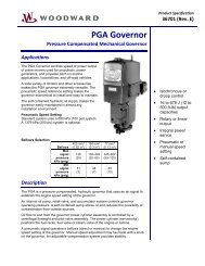
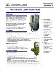
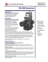
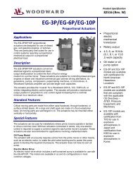
The EG-3P/6P/10P (proportional)<br />
actuators are designed for use on diesel,<br />
gas, and gasoline engines, or turbines.<br />
They are particularly well suited for use in<br />
control systems requiring a proportional<br />
mechanical output or a proportional<br />
electrical input.<br />
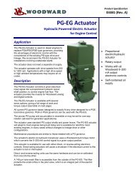
Description<br />
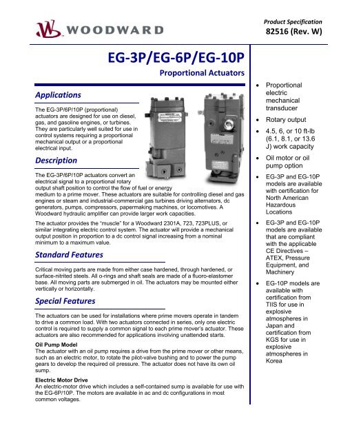
<strong>EG‐3P</strong>/<strong>EG‐6P</strong>/<strong>EG‐10P</strong><br />
Proportional Actuators<br />
The EG-3P/6P/10P actuators convert an<br />
electrical signal to a proportional rotary<br />
output shaft position to control the flow of fuel or energy<br />
medium to a prime mover. These actuators are suitable for controlling diesel and gas<br />
engines or steam and industrial-commercial gas turbines driving alternators, dc<br />
generators, pumps, compressors, papermaking machines, or locomotives. A<br />
Woodward hydraulic amplifier can provide larger work capacities.<br />
The actuator provides the “muscle” for a Woodward 2301A, 723, 723PLUS, or<br />
similar integrating electric control system. The actuator will provide a mechanical<br />
output position in proportion to a dc control signal increasing from a nominal<br />
minimum to a maximum value.<br />
Standard Features<br />
Critical moving parts are made from either case hardened, through hardened, or<br />
surface-nitrited steels. All o-rings and shaft seals are made of a fluoro-elastomer<br />
base. All moving parts are submerged in oil. The actuators may be mounted either<br />
vertically or horizontally.<br />
Special Features<br />
The actuators can be used for installations where prime movers operate in tandem<br />
to drive a common load. With two actuators connected in series, only one electric<br />
control is required to supply a common signal to each prime mover’s actuator. These<br />
actuators are also recommended for applications involving unattended starts.<br />
Oil Pump Model<br />
The actuator with an oil pump requires a drive from the prime mover or other means,<br />
such as an electric motor, to rotate the pilot-valve bushing and to power the pump<br />
gears to develop the required oil pressure. The actuator does not have its own oil<br />
sump.<br />
Electric Motor Drive<br />
An electric-motor drive which includes a self-contained sump is available for use with<br />
the EG-6P/10P. The motors are available in ac and dc configurations in most<br />
common voltages.<br />
<br />
<br />
<br />
<br />
<br />
<br />
<br />
Product Specification<br />
82516 (Rev. W)<br />
Proportional<br />
electric<br />
mechanical<br />
transducer<br />
Rotary output<br />
4.5, 6, or 10 ft-lb<br />
(6.1, 8.1, or 13.6<br />
J) work capacity<br />
Oil motor or oil<br />
pump option<br />
EG-3P and EG-10P<br />
models are available<br />
with certification for<br />
North American<br />
Hazardous<br />
Locations<br />
EG-3P and EG-10P<br />
models are available<br />
that are compliant<br />
with the applicable<br />
CE Directives –<br />
ATEX, Pressure<br />
Equipment, and<br />
Machinery<br />
EG-10P models are<br />
available with<br />
certification from<br />
TIIS for use in<br />
explosive<br />
atmospheres in<br />
Japan and<br />
certification from<br />
KGS for use in<br />
explosive<br />
atmospheres in<br />
Korea
Woodward 82516 p.2<br />
Oil Motor Model<br />
An oil motor actuator requires a supply of 80 to 500 psi (552 to 3448 kPa) pressure oil from an external source to rotate<br />
the pilot valve bushing and to provide the required work. Work output and stalled torque of the oil motor model are in<br />
direct proportion to the supply pressure.<br />
Compensation<br />
Many EG actuators operate with oil supplied directly from the prime mover. Certain multiviscosity motor oils require a<br />
compensation system within the actuator to provide needed stability. A needle valve is included in the compensation<br />
system to allow response adjustment.<br />
Radiation Resistance<br />
Radiation-resistant parts are available for special applications.<br />
Position Feedback<br />
A position feedback transducer (RVDT) is available to monitor output shaft position.<br />
Note: Unless otherwise specified, these actuators are tested and shipped for vertical operation. When used in a<br />
horizontal application, these actuators will have an 8 degree shift in terminal shaft calibration.<br />
References<br />
Manual 82560 EG-3P Actuator<br />
Manual 82566 EG-6P/10P Actuator<br />
Manual 56102 Hydraulic Amplifier (Elec. Controlled)<br />
Manual 25071 Oils for Hydraulic Controls<br />
Regulatory Compliance<br />
European Compliance for CE Marking:<br />
These listings are limited only to those EG-3P or EG-10P units bearing the CE Marking.<br />
ATEX Directive: 94/9/EC EG-3P—LCIE 06 ATEX 6109X<br />
EG-10P—LCIE 12 ATEX 3046X<br />
Zone 1, Category 2 Group II G, Ex e IIC T4 Gb; EG-3P—T6<br />
Self-declared to Zone 2, Category 3, Group II G, EEx nC IIC T3<br />
Note: A 900 mA fuse or motor protection switch must be provided for each torque motor. Measures must<br />
be taken not to exceed 30 V nominal with a 480 V switch-off over voltage. Current limitations are<br />
provided by the electronic control device.<br />
Other European Compliance:<br />
Compliance with the following European Directives or standards does not qualify this product for application of the<br />
CE Marking:<br />
EMC Directive: Not applicable to this product. Electromagnetically passive devices are excluded<br />
from the scope of the 2004/108/EC Directive<br />
Machinery Directive: Compliant as partly completed machinery with 2006/42/EC<br />
Pressure Equipment<br />
Directive: Compliant as “SEP” per Article 3.3 to 97/23/EC<br />
Other International Compliance for EG-10P:<br />
TIIS: Certified for use in explosive atmospheres in Japan per TIIS Certificate Numbers<br />
TC18079 and TC18151 as Ex e II T3.<br />
Korea: Certified for use in explosive atmospheres in Korea per KGS Certificate Number<br />
06-2-046-Q1 as Ex e II T3<br />
IECEx: Certified for use in hazardous locations IECEx LCIE 12.0001X Ex e IIC T4 Gb IP54<br />
North American Compliance:<br />
These listings are limited only to those units bearing the CSA or UL agency identification.<br />
EG-3P: CSA Certified for Class I, Division 2, Groups A, B, C, D, T4 for use in Canada and<br />
the United States and UL Listed for Class I, Division 2, Groups B, C, D, T4 for use in<br />
the United States<br />
EG-10P: CSA Certified for Class I, Division 1, Group D, and Division 2, Groups B, C, D, T3 for<br />
use in Canada and UL Listed for Class I, Division 1, Groups B, C, D and Division 2,<br />
Groups B, C, D, T3 for use in the United States<br />
EG-10P with RVDT: CSA Certified for Class I, Division 1, Group D and Division 2, Groups B, D, T3 for<br />
use in Canada and UL Listed for Class I, Division 1, Groups B, C, D and Division 2,<br />
Groups B, D, T3 for use in the United States<br />
EG-10PS: CSA Certified for Class I, Divisions 1 and 2, Group D, T3 for use in Canada and UL<br />
Listed for Class I, Divisions 1 and 2, Group D for use in the United States
Specifications<br />
Woodward 82516 p.3<br />
All Models<br />
Output Shaft ............................................ 0.375”-36 serrations (standard/EG-3P) both sides of the case; 0.500”-36<br />
serrations (standard/EG-6P/10P) either side of the case. Special output<br />
shafts are available.<br />
Angular Travel ......................................... 42° nominal travel available with 28° travel from no load to full load at rated<br />
speed recommended.<br />
Calibration ............................................... 2° to 3° off minimum shaft position at 20 mA. 36° ±3° additional travel at<br />
160 mA.<br />
Temperature Drift .................................... Nominally ±1° of output per 100 °F/56 °C<br />
Transducer Coil Resistance .................... Single Coil Units: 30 to 35 at 20 °C / 68 °F<br />
Dual Coil Units: 14 to 16 Ω at 20 °C / 68 °F<br />
Nominal Coil Input Current Range .......... 20 to 160 mA for single or two actuators operating from one electric control.<br />
Electrical Connector ................................ 4-pin S2102-14S-2P. Hazardous location electrical connections are screw<br />
terminals in a conduit box.<br />
Hydraulic Oil Supply Fluid ....................... Hydrocarbon oil. Consult Woodward for recommended synthetic oils. If<br />
multiviscosity oils are used, the compensated model is suggested.<br />
Hydraulic Oil Viscosity ............................. 100 to 200 SUS at operating temperature recommended. 50 SUS minimum,<br />
3000 SUS maximum (7.5 CST to 850 CST).<br />
Oil Temperatures of Continuous<br />
Operation .................................... 140 to 200 °F/60 to 93 °C depending on oil viscosity.<br />
Ambient Temperature Range .................. –20 to +200 °F/–29 to +93 °C. The primary temperature concern is for the<br />
hydraulic fluid properties in the actuator.<br />
Case and Base Construction................... Cast or ductile iron.<br />
Cover, Subcap, and Drain Adapter ......... Cast aluminum.<br />
Mounting Configuration ........................... Vertical (or horizontal with proper adjustments; non-interchangeable).<br />
Mounting Studs ....................................... Two 5/16” diameter (EG-3P); four 5/16” diameter (EG-6P/10P).<br />
Oil Pump Models (EG-3P/10P)<br />
Work Output ............................................ EG-3P—Maximum 4.5 ft-lb (6.1 J). Travel is 2/3 full travel for a work output<br />
of 3.0 ft-lb (4.1 J). Stalled torque rating is 6.2 lb-ft (8.4 N•m).<br />
EG-10P—Maximum 9.3 ft-lb (12.6 J). Travel is 2/3 full travel for a work<br />
output of 6.2 ft-lb (8.4 J). Stalled torque rating is 12.8 lb-ft (17.4 N•m).<br />
Time Constant ......................................... 0.08 second (EG-3P); 0.17 second (EG-10P).<br />
Hydraulic Source ..................................... Engine lubricating system or a separate sump.<br />
Supply Pressure ...................................... EG-3P—1 ft (300 mm) of lift to a maximum of 100 psi (690 kPa).<br />
EG-10P—1 ft (300 mm) of lift to a maximum of 50 psi (345 kPa).<br />
Flow ......................................................... Peak demand of 2 US gal/min (7.6 L/min) during transients; steady-state<br />
flow of 0.5 US gal/min (1.9 L/min) with 250 SUS oil supply.<br />
Filter ......................................................... 20 to 25 µm (nominal).<br />
Pump Capacity ........................................ 92.7 cubic inches (1519 cm³)/minute/1000 rpm.<br />
Pump Power Required ............................ EG-3P—0.5 hp (373 W) at 1800 rpm recommended for motor drive.<br />
EG-10P—0.18 hp (134 W) at 1000 rpm required for EG-10P. 0.5 hp (373 W)<br />
at 1000 rpm recommended for motor drive.<br />
Supply Inlet .............................................. 0.250”-18 NPTF (2). Use one or supply through mounting surface.<br />
Drain ........................................................ 11/32” dia. base, must have free discharge. For horizontal mounting, use<br />
0.250-18 NPTF in cover.<br />
Weight ..................................................... EG-3P—9.25 lb (4.2 kg).<br />
EG-10P—16.0 lb (7.3 kg).<br />
Drive Rotation .......................................... Plugged for either clockwise or counterclockwise.<br />
Recommended Drive Speed ................... 1500 to 4000 rpm.<br />
Drive Coupling ......................................... EG-3P—.562-6 spline extends 0.375” (9.5 mm) from mounting hub<br />
(standard).<br />
EG-10P—.562-6 spline extends 0.562” (14.3 mm) from mounting surface<br />
(standard).
Oil Motor (EG-3P/10P)<br />
Work Output:<br />
Recommended Output Shaft<br />
Actuator Operating Maximum Work Travel is 2/3 Full Travel for a<br />
Oil Pressure Output Work Output of:<br />
EG-3P 400 psi 2758 kPa 4.5 ft-lb 6.1 J 3.0 ft-lb 4.1 J<br />
300 2068 3.3 4.5 2.2 3.0<br />
200 1379 2.2 3.0 1.4 1.9<br />
100 690 1.1 1.5 0.7 0.9<br />
EG-10P 400 2758 9.3 12.6 6.2 8.4<br />
300 2068 7.0 9.5 4.7 6.4<br />
200 1379 4.6 6.2 3.1 4.2<br />
100 690 2.3 3.1 1.5 2.0<br />
Woodward 82516 p.4<br />
Time Constant ......................................... EG-3P—0.5P –1/2 + 0.0028P 1/2 sec<br />
EG-10P—1.06P –1/2 + 0.0059P 1/2 sec.<br />
where P=supply pressure in psig (1 psig=6.895 kPa).<br />
Supply Pressures .................................... 80 to 500 psi (552 to 3448 kPa). Pressures outside this range are not<br />
recommended.<br />
Supply Flow ............................................. Peak demand of 4 US gal/min (15 L/min) during transients. Steady-state<br />
flow 1.4 US gal/min (5.3 L/min) maximum, depending on orifice size and<br />
operating pressure.<br />
Filter ........................................................ 10 to 15 µm (nominal).<br />
Pressure Inlet .......................................... 0.250”-18 NPTF to pilot valve.<br />
Orifice (to oil motor supply):<br />
Supply Pressure<br />
Orifice Diameter<br />
(psi) (kPa) (inch) (mm)<br />
80 to 1207 to 2068 0.055 1.4<br />
>300 to 500 >2068 to 3448 0.047 1.2<br />
Drain ........................................................ 0.75”-14 NPTF on drain adapter. Must have free discharge. For horizontal<br />
mounting, use 0.250”-18 NPTF in cover.<br />
Weight ..................................................... EG-3P—11 lb (5 kg)<br />
EG-10P—17 lb (8 kg)<br />
PO Box 1519, Fort Collins CO, USA 80522-1519<br />
1000 East Drake Road, Fort Collins CO 80525<br />
Tel.: +1 (970) 482-5811 • Fax: +1 (970) 498-3058<br />
www.woodward.com<br />
For more information contact:<br />
Distributors & Service<br />
Woodward has an international network of distributors and service facilities.<br />
For your nearest representative, call the Fort Collins plant or see the<br />
Worldwide Directory on our website.<br />
This document is distributed for informational purposes only. It is not to be construed as<br />
creating or becoming part of any Woodward contractual or warranty obligation unless<br />
expressly stated in a written sales contract.<br />
Copyright © Woodward 1970–2012, All Rights Reserved<br />
2012/8/Colorado