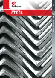
CATALOGUE
Hurricane HRC Mesh Handbook - Steel & Tube
Hurricane HRC Mesh Handbook - Steel & Tube
- No tags were found...

Create successful ePaper yourself
Turn your PDF publications into a flip-book with our unique Google optimized e-Paper software.
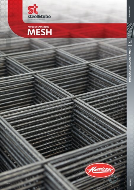
PRODUCT <strong>CATALOGUE</strong> MESH<br />
REINFORCING<br />
PRODUCT <strong>CATALOGUE</strong><br />
MESH<br />
S&T025<br />
JAN 2013
INDEX<br />
Introduction 1<br />
NZ Standards relating to Steel Wire Fabric 2<br />
Sheet Sizes 3 & 4<br />
Standard Meshes, Wire Size, Pitch, Mass and Volume 5<br />
Lappages 6<br />
Lap Examples 7<br />
Lap Charts 8<br />
Bar to Mesh Conversions 9<br />
Conversion Chart 10<br />
Mass per m2 for Wire Sizes 11<br />
Area per Metre Width for Wire Sizes 12<br />
Wire/Steel Charts 13 & 14<br />
Mechanical Limitations of Fabrication 15
INTRODUCTION<br />
This Handbook has been produced for the Civil and Structural Engineering professions as an information resource on<br />
the nature of steels, welding processes and design criteria for welded fabric. It will also aid designers in assessing<br />
and calculating steel wire fabric options for specific constructional requirements.<br />
The standard listing of products, sizes, applications and additional related services available will also be relevant to<br />
the Construction Industry in general.<br />
Whilst every effort has been made to ensure the accuracy of any information, advice or recommendations it may offer,<br />
no liability or responsibility of any kind is accepted in this respect.<br />
1
NEW ZEALAND STANDARDS<br />
The Standards Association of New Zealand controls the preparation and publishing of all Standard Specifications and<br />
Codes of Practice in New Zealand.<br />
The New Zealand Standards mentioned in this section, control the mechanical properties of the steel wire used for<br />
concrete reinforcement, the fabrication of the welded fabric and the methods of application in respect to concrete<br />
reinforcement.<br />
Further information can be obtained from:<br />
Standards Association of New Zealand, Private Bag Wellington<br />
NZ3421:1975<br />
Specification for Hard Drawn Mild Steel Wire for Concrete Reinforcement<br />
The Standard requires the following tensile properties:-<br />
NOMINAL DIAMETER (mm)<br />
MINIMUM 0.2% PROOF TENSILE STRENGTH (MPa)<br />
STRESS (MPa)<br />
Maximum<br />
Minimum<br />
Up to and including 3.15 485 575 855<br />
Over 3.15 485 575 775<br />
NZ3422:1975<br />
Specification for Welded Fabric of Drawn Steel Wire for Concrete Reinforcement<br />
This Standard requires a minimum average Weld Shear load “Where the longitudinal wire diameter is in the range<br />
11mm to 3.15mm and the longitudinal to transverse wire diameter differential does not exceed 3mm, the minimum<br />
average shear value in Newtons shall be not less than 240 multiplied by the cross-sectional area of the longitudinal<br />
wire in square millimetres”, and dictates requirements of “The distance between centres of two adjacent wires shall<br />
not vary by more than 7.5 percent from the exact pitch”. “If fabric is required to be cut to specific dimensions, the<br />
tolerance shall be as follows”:<br />
5 Metres and under +25mm<br />
Over 5 metres +0.5%<br />
NZS3101:2006<br />
Code of Practice for The Design of Concrete Structures<br />
This Standard lays out the development length and lap-splice requirements for plain wire fabric and deformed wire<br />
fabric, and is the basis of any pertinent calculations or recommendations given in this Handbook.<br />
2
SHEET SIZES<br />
Standard production sheet sizes have been designed to offer the user an economical unit for construction purposes.<br />
The Dimensions offered relate to NZ Standard lap requirements’ fabrication limitations and also to on-site handling<br />
practicalities.<br />
Sheets can be fabricated to specific dimensional requirements if quantities are sufficient to make production runs<br />
viable. However, the following are offered as stock product.<br />
The dimensions shown are overall sheet sizes and include the end and side overhangs.<br />
Standard HRC overhangs are nominally 20mm either side. The end overhang is nominally half the pitch (i.e. on a 66<br />
Mesh the end overhang is 150<br />
2 = 75mm).<br />
3
DEFORMED MESH<br />
668 Equivalent:<br />
D84 5.6 dia deformed wire at 300 centres<br />
Overall size 2290 x 5100<br />
Effective area after lapping 10.08m 2<br />
Utilises double selvedge wires<br />
665 Equivalent:<br />
D147 7.5 dia deformed wire at 300 centres<br />
Overall size 2400 x 6900<br />
Effective area after lapping 13.86m 2<br />
Utilises equal overhangs<br />
Deformed Meshes are designed to exactly match the<br />
traditional “66” meshes for strength while minimising<br />
wastage of materials in the lap area.<br />
The D numbers are taken from the nominal sectional<br />
area of steel per metre width presented by the<br />
welded wire fabric.<br />
664 Equivalent:<br />
D188 6.0 dia deformed wire at 150 centres<br />
Overall size 2400 x 6900<br />
Effective area after lapping 13.86m 2<br />
Utilises asymmetric overhangs<br />
663 Equivalent:<br />
D212 6.3 dia deformed wire at 150 centres<br />
Overall size 2400 x 6900<br />
Effective area after lapping 13.86m 2<br />
Utilises asymmetric overhangs<br />
662 Equivalent:<br />
D264 7.1 dia deformed wire at 150 centres<br />
Overall size 2400 x 6900<br />
Effective area after lapping 13.86m 2<br />
Utilises asymmetric overhangs<br />
661 Equivalent:<br />
D295 7.5 dia deformed wire at 150 centres<br />
Overall size 2400 x 6900<br />
Effective area after lapping 13.86m 2<br />
Utilises asymmetric overhangs<br />
4
STANDARD SHEET SIZES<br />
HRC SHEET<br />
TYPE<br />
WIRE SIZE<br />
(mm)<br />
PITCH<br />
(mm)<br />
STEEL AREA<br />
per METRE<br />
WIDTH<br />
(mm 2 )<br />
SHEET SIZE<br />
(mm x mm)<br />
NET COVER<br />
AFTER<br />
LAPPING<br />
(m 2 )<br />
MASS<br />
per m 2<br />
SHIPING<br />
VOLUME<br />
per 100m 2<br />
661 Ecomomy 7.5 150 294.5 2440 x 6150 4.728 4.728 1.38<br />
663 Economy 6.3 150 207.8 2440 x 6150 12.76 3.337 0.92<br />
665 Economy 5.3 150 147.1 2440 x 6150 12.76 2.362 0.78<br />
668 Economy 4.0 150 83.8 2440 x 6150 12.76 1.344 0.59<br />
661 Large 7.5 150 294.5 1990 x 4650 7.52 4.752 1.38<br />
662 Large 7.1 150 263.9 1990 x 4650 7.52 4.258 1.30<br />
663 Large 6.3 150 207.8 1990 x 4650 7.52 3.353 0.92<br />
664 Large 6.0 150 188.5 1990 x 4650 7.52 3.042 0.88<br />
665 Large 5.3 150 147.1 1990 x 4650 7.52 2.373 0.78<br />
668 Large 4.0 150 83.8 1990 x 4650 7.52 1.351 0.59<br />
333 Large 6.3 75 415.6 1990 x 4650 7.66 6.582 1.16<br />
335 Large 5.3 75 294.2 1990 x 4650 7.96 4.659 0.97<br />
338 Large 4.0 75 167.6 1990 x 4650 7.96 2.652 0.59<br />
D84 5.6 Def 300 84.8 2290 x 5100 10.08 1.210 1.25<br />
D147 7.5 Def 300 147.3 2400 x 6900 13.86 2.126 1.60<br />
D188 6.0 Def 150 188.5 2400 x 6900 13.86 2.715 1.61<br />
D212 6.3 Def 150 207.8 2400 x 6900 13.86 3.029 1.61<br />
D264 7.1 Def 150 263.9 2400 x 6900 13.86 3.812 1.60<br />
D295 7.5 Def 150 294.5 2400 x 6900 13.86 4.251 1.61<br />
5
LAPPAGES<br />
Lap-splice requirements for Welded Wire Mesh are set by the NZ Standards Association in NZS3101:2006 and are<br />
subject to a number of variables.<br />
The following charts have been calculated for the convenience of the user. It is believed that most design situations<br />
will be satisfied; however, no responsibility for design accuracy can be assumed and designers should refer back to<br />
NZS3101:2006 for substantiating calculations.<br />
The design assumptions made for these charts are listed below.<br />
Notice should be taken of the NZ Standards Association’s differential of requirements for plain wire fabric and<br />
deformed wire fabric.<br />
Similar lap-splice requirements are not acceptable, and current sheet designs are tailored to suit NZ Standards<br />
requirements.<br />
For this reason, deformed wire mesh lappages are calculated as per deformed bar.<br />
Assumptions as listed are referenced in terms of NZS3101 Nomenclature.<br />
fy = 485 MPa Yield strength of steel<br />
F’ = 25 MPa Compressive strength of concrete<br />
Asr/Asp = 1.0 Ratio of steel required to steel provided<br />
C = 20mm + db/2 Concrete over<br />
The following charts list “overall” lap-splice requirements of Welded wire fabric in as much as they show the required<br />
overlap of mesh from the perimeter of the sheet.<br />
6
LAP DIAGRAMS<br />
7
LAPPING<br />
8
LAPPAGES<br />
CONVERSIONS<br />
MESH COMMENTS SIDE LAP END<br />
661<br />
662<br />
663<br />
664<br />
665<br />
668<br />
D84<br />
D147<br />
D188<br />
D212<br />
D264<br />
D295<br />
84XP<br />
147XP<br />
2 Wires plus<br />
50mm for<br />
encasement<br />
plus overhangs<br />
Overhangs to<br />
reach edge wire<br />
2 Squares of<br />
double edge<br />
wires plus<br />
overhangs<br />
240 350<br />
300 300<br />
190 225<br />
NOTE: If sheets are cut and overhang or edge<br />
wire detail is lost, laps must revert to:<br />
2 Wires plus 50mm in the lap zone<br />
• In some circumstances such as building slabs,<br />
reinforcing bar can be substituted with<br />
welded mesh.<br />
• There are substantial savings in labour and time<br />
that can be gained by using welded mesh instead<br />
of tied re-bar.<br />
• The quick reference conversion chart on page 10,<br />
makes allowance for the differences in design<br />
strengths of 500 grade and 300 grade re-bar<br />
and the 485 proof stress of hard drawn<br />
reinforcing wire.<br />
• Eg: from the chart, H10 @ 300 = 662 = D264<br />
Which means 10 diameter 500 grade bar at<br />
300mm centres can be substituted with 662 mesh<br />
or D264 construction mesh.<br />
9
QUICK REFERENCE<br />
CONVERSION CHART<br />
10
MASS PER SQUARE METRE FOR WIRES<br />
IN ONE DIRECTION AT VARIOUS SPACINGS<br />
DIA<br />
Kg PER<br />
LINEAL<br />
WIRE SPACINGS – kgs<br />
50mm 75mm 100mm 150mm 200mm 225mm 250mm 300mm<br />
11.20 .773387 15.4677 10.3118 7.7339 5.1559 3.8669 3.4373 3.0935 2.5780<br />
10.00 .616539 12.3308 8.2205 6.1654 4.1103 3.0827 2.7402 2.4662 2.0551<br />
9.50 .556427 11.1285 7.4190 5.5643 3.7095 2.7821 2.4730 2.2257 1.8548<br />
9.00 .499397 9.9876 6.6586 4.9940 3.3293 2.4970 2.2257 1.9976 1.6647<br />
8.00 .394585 7.8917 5.2611 3.9459 2.6306 1.9729 1.7537 1.5783 1.3153<br />
7.50 .346804 6.9361 4.6241 3.4680 2.3120 1.7340 1.5413 1.3872 1.1560<br />
7.10 .310797 6.2159 4.1440 3.1080 2.0720 1.5540 1.3813 1.2432 1.0360<br />
6.30 .244704 4.8941 3.2627 2.4470 1.6314 1.2235 1.0876 0.9788 0.8157<br />
6.00 .221954 4.4391 2.9594 2.2195 1.4797 1.1098 0.9865 0.8878 0.7398<br />
5.30 .173186 3.4637 2.3091 1.7319 1.1546 0,8659 0.7697 0.6927 0.5773<br />
5.00 .154135 3.0827 2.0551 1.5414 1.0276 0.7707 0.6850 0.6165 0.5138<br />
4.00 .098646 1.9729 1.3153 0.9865 0.6576 0.4932 0.4384 0.3946 0.3288<br />
3.15 .061176 1.2235 0.8157 0.6118 0.4078 0.3059 0.2719 0.2447 0.2039<br />
11
SECTIONAL AREA PER METRE WIDTH<br />
DIA<br />
SECTIONAL<br />
AREA mm<br />
sq<br />
WIRE SPACINGS – mm sq<br />
50mm 75mm 100mm 150mm 200mm 225mm 250mm 300mm<br />
11.20 98.5206 1970.41 1313.61 985.21 656.80 492.60 437.87 394.08 328.40<br />
10.00 78.5400 1570.80 1047.20 785.40 523.60 392.70 349.07 314.16 261.80<br />
9.50 70.8824 1417.65 945.10 708.82 472.55 354.41 315.03 283.53 236.27<br />
9.00 63.6174 1272.35 848.23 636.17 424.12 318.09 282.74 254.47 212.06<br />
8.00 50.2626 1005.31 670.21 502.66 335.10 251.33 223.40 201.06 167.55<br />
7.50 44.1788 883.58 589.05 441.79 294.53 220.89 196.35 176.72 147.26<br />
7.10 39.5920 791.84 527.89 395.92 263.95 197.96 175.96 158.37 131.97<br />
6.30 31.1725 623.45 415.63 311.73 207.82 155.86 138.54 124.69 103.91<br />
6.00 28.2744 565.49 376.99 282.74 188.50 141.37 125.66 113.10 94.25<br />
5.30 22.0619 441.24 294.16 220.62 147.08 110.31 98.05 88.25 73.54<br />
5.00 19.6350 392.70 261.80 196.35 130.90 98.18 87.27 78.54 65.45<br />
4.00 12.5664 251.33 167.55 125.66 83.78 62.83 55.85 50.27 41.89<br />
3.15 7.7931 155.86 103.91 77.93 51.95 38.97 34.64 31.17 25.98<br />
12
WIRE CHART<br />
DIAMETER mm<br />
NEAREST<br />
ISWG<br />
CROSS SECTIONAL<br />
AREA mm2<br />
kg PER METRE<br />
METRES PER kg<br />
11.20 5/0 98.52 0.7734 1.2930<br />
10.00 4/0 78.54 .6165 1.6620<br />
9.50 3/0 70.88 .5564 1.7972<br />
9.00 2/0 63.62 .4994 2.0024<br />
8.00 1/0 50.27 .3946 2.5343<br />
7.50 1 44.18 .3468 2.8835<br />
7.10 2 39.59 .3108 3.2175<br />
6.30 3 31.17 .2447 4.0866<br />
6.00 4 28.27 .2220 4.5054<br />
5.30 5 22.06 .1732 5.7741<br />
5.00 6 19.63 .1541 6.4878<br />
4.50 7 15.90 .1249 8.0096<br />
4.00 8 12.57 .0986 10.1373<br />
3.55 9 9.90 .0777 12.8702<br />
3.15 10 7.79 .0612 16.3463<br />
2.80 11 6.16 .0483 20.6881<br />
2.50 12 4.91 .0385 25.9511<br />
2.24 13 3.94 .0309 32.3258<br />
2.00 14 3.14 0.0247 40.4582<br />
1.80 15 2.54 .0200 50.0601<br />
1.60 16 2.01 .0158 63.3593<br />
1.40 17 1.54 .0121 82.7541<br />
1.25 18 1.23 .0096 103.810<br />
1.00 19 0.79 .0062 162.206<br />
0.90 20 .064 .0050 200.240<br />
13
STEEL BAR CHART<br />
DIAMETER mm<br />
CROSS SECTIONAL<br />
AREA mm 2<br />
MASS PER UNIT<br />
LENGTH kg/m<br />
LENGTH PER 1000kg<br />
6.0 28.27 0.222 4505<br />
10.0 78.54 0.617 1622<br />
12.0 113.10 0.888 1126<br />
16.0 201.06 1.578 633<br />
20.0 314.16 2.466 405<br />
24.0 452.39 3.551 281<br />
28.0 615.75 4.834 206<br />
32.0 804.25 6.313 158<br />
40.0 1256.64 9.865 101<br />
14
MECHANICAL LIMITATIONS<br />
Welded Wire Fabric is produced from a series of longitudinal and transverse steel wires, resistance welded at all<br />
intersections.<br />
The manufacturing process can be varied to accommodate various style changes and dimensions. (However,<br />
consideration should be given to the complexity of the change). The manufacturing variables are listed in the general<br />
order of time involved, starting with the most time consuming.<br />
(a) Longitudinal wire spacing (b) Width of sheet (c) Side and end overhangs (d) Transverse wire spacing (e) Transverse<br />
wire size (f) Longitudinal wire size (g) Length of sheet.<br />
The more difficult machine changes require greater quantities per item in order to offset the additional production<br />
time required. Generally, it is more economical to order a few basic sheet sizes and styles than to specify many<br />
variations in the sheet.<br />
The following maximum dimensions are given as a guide but may be subject to regional variations due to differences<br />
in plant.<br />
Maximum overall width 2700mm<br />
Maximum overall length 7000mm<br />
Maximum number of longitudinal wires 36<br />
15
HURRICANE<br />
REINFORCING MESH TESTING<br />
New Zealand Standards for reinforcing meshes require<br />
it to be tested in specified batch lots before it can<br />
be claimed to comply with those Standards. Hence<br />
Hurricane maintains two laboratories in New Zealand<br />
specifically to test manufactured reinforcing meshes<br />
for compliance and to provide test certification of<br />
those results. Hurricane Wire Products is in the unique<br />
position of being able to offer proof of compliance with<br />
all reinforcing meshes supplied.<br />
The following tests form the basis of the information<br />
required to provide the designer with confidence in the<br />
performance of the mesh at work.<br />
WELD SHEAR<br />
Weld Shear is a critical test for reinforcing meshes as the welded<br />
crosswire is often an integral part in the mechanics of lappage and<br />
provides the major proportion of the anchorage in concrete. Both<br />
NZS 3422 and AS/NZS 4671 requirements must be met to satisfy<br />
Hurricanes internal controls.<br />
DEFORMATION TEST<br />
The surface geometry of the reinforcing mesh plays a significant role<br />
in increasing the bond with the concrete. The relationship of the ribbed<br />
projections to the nominal diameter is critical and material tested must<br />
meet the requirements of AS/NZS 4671.<br />
MASS CALCULATION<br />
With the proliferation of deformed meshes the measurement of wire<br />
diameters became impractical; hence the measurement of mass now<br />
provides the evidence for design confidence. AS/NZS 4671 provides<br />
cross-sectional areal for nominal diameters and tolerances of 4.5% plus<br />
or minus on mass per metre results.<br />
TENSILE TEST<br />
The hard drawn nature of reinforcing wire produces high tensile<br />
strengths with low ductility. This prevents the observation of a yield<br />
phenomenon and hence the 0.2% proof stress is determined by<br />
test as detailed in both NZS 3422 and AS/NZS 4671. The minimum<br />
requirement remains at 485MPa.<br />
SET DOWN<br />
Set Down of the welded wires is not a test required by any Standards<br />
Authority. Rather it is an empirical measure from the experience gained<br />
from 60 years of manufacture by New Zealand’s first mesh producer<br />
and is an effective indicator of the quality of the welding process.
To find out more about our extensive range<br />
of products and services:<br />
Steel<br />
Rural Products<br />
Pipe, Fittings & Valves Industrial Products<br />
Stainless Steel<br />
Reinforcing<br />
Fastenings<br />
Roofing, Cladding,<br />
Chain & Rigging<br />
Rainwater Systems<br />
& Purlins<br />
CONTACT US TODAY:<br />
0800 800 947<br />
or Freefax 0800 808 141<br />
www.steelandtube.co.nz<br />
S&T028