Automation platform Modicon Premium
Automation platform Modicon Premium
Automation platform Modicon Premium

You also want an ePaper? Increase the reach of your titles
YUMPU automatically turns print PDFs into web optimized ePapers that Google loves.
<strong>Automation</strong> <strong>platform</strong><br />
<strong>Modicon</strong> <strong>Premium</strong><br />
Catalogue<br />
2008
A full range of catalogues for . . . . .<br />
Safety Functions<br />
and Solutions<br />
using Preventa<br />
Catalogue<br />
2008/2009<br />
Detection<br />
<strong>Automation</strong><br />
<strong>Automation</strong><br />
Operator dialog<br />
Motion and Drives<br />
<br />
Global Detection<br />
Electronic and<br />
electromechanical sensors<br />
n° 960262<br />
MKTED208052EN<br />
Photo-electric sensors<br />
Proximity sensors<br />
Capacitive proximity sensors<br />
Ultrasonic sensors<br />
Limit switches<br />
Pressure switches<br />
Rotary encoders<br />
Radio frequency identification<br />
Machine cabling accessories<br />
<br />
<strong>Modicon</strong> Momentum<br />
distributed I/O and control<br />
n° 807861<br />
MKTED205061EN<br />
<br />
<strong>Modicon</strong> Quantum<br />
automation <strong>platform</strong>, Unity,<br />
Concept & ProWORX 32<br />
n° 960237<br />
MKTED208011EN<br />
<br />
<strong>Modicon</strong> <strong>Premium</strong> and<br />
Unity - PL7 software<br />
n° 960268<br />
MKTED208054EN<br />
<br />
<strong>Modicon</strong> M340 and<br />
Unity software<br />
n° 960128<br />
DIAED2061001EN<br />
PLCs<br />
Discrete, analogue I/O and<br />
application-specifi c solutions<br />
Communication<br />
<br />
Twido programmable<br />
controller and TwidoSuite<br />
software<br />
n° 960211<br />
DIA3ED2070902EN<br />
Controller base<br />
Discrete, analogue I/O<br />
Communication<br />
<br />
<strong>Automation</strong> functions,<br />
relays, interfaces and<br />
power supplies<br />
n° 960162<br />
MKTED207031EN<br />
Smart relays<br />
Timing relays<br />
Measurement & control relays<br />
Analogue interfaces<br />
Counters<br />
Plug-in relays<br />
Interfaces for discrete signals<br />
Power supplies & transformers<br />
Software<br />
PLCs and safety controllers<br />
programming software<br />
<br />
Control and signalling<br />
components<br />
n° 960239<br />
MKTED208031EN<br />
Control and signalling units<br />
Control stations & enclosures<br />
Cam switches<br />
Beacons and indicator banks<br />
Pendant control stations<br />
Controllers<br />
Emergency stops<br />
Foot switches<br />
<br />
Human-Machine interfaces<br />
n° 821230<br />
MKTED206071EN<br />
Operator interface terminals<br />
Industrial PCs<br />
HMI and SCADA PC-based<br />
software<br />
Software<br />
Vijeo Designer<br />
Operator terminal software<br />
<br />
Motion control Lexium 05<br />
n° 808610<br />
DIA7ED2050910EN<br />
<br />
Motion control Lexium 15<br />
n° 816811<br />
DIA2ED2060506EN<br />
<br />
Lexium Controller motion<br />
controllers<br />
n° 960165<br />
DIA7ED2070410EN<br />
Servo drives and Servo motors<br />
Motion controllers<br />
Motion control modules<br />
<strong>Modicon</strong> <strong>Premium</strong> and <strong>Modicon</strong><br />
Quantum<br />
<br />
Soft starters and variable<br />
speed drives<br />
n° 960142<br />
MKTED206111EN<br />
Soft starters and variable speed<br />
drives<br />
Software<br />
Software for drives and motors<br />
Motor control programming<br />
software<br />
Not all products shown in this catalogue are available in every country. Check individual country’s web site or Sales Offi ce for product availability.<br />
See on: www.schneider-electric.com
. . . . all <strong>Automation</strong> & Control functions<br />
Motor control<br />
Machine safety<br />
Interfaces and I/O<br />
Power supplies<br />
Systems & architectures<br />
&<br />
Motor starter solutions<br />
Control and protection<br />
components<br />
n° 814711<br />
MKTED205103EN<br />
Contactors<br />
Circuit-breakers, fuse carriers<br />
Thermal relays<br />
Combinations, motor controllers<br />
Mounting solutions<br />
Motor starter mounting kits<br />
This catalogue contains<br />
<strong>Automation</strong> and Control function<br />
products relating to machines<br />
Safety<br />
&<br />
Safety functions and<br />
solutions using Preventa<br />
n° 960260<br />
MKTED208051EN<br />
Safety PLCs<br />
Safety controllers<br />
Safety monitors<br />
Safety solutions on AS-Interface<br />
cabling system<br />
Safety switches<br />
Safety light curtains<br />
Safety mats<br />
Emergency stops<br />
Control stations<br />
Enabling switches<br />
Foot switches<br />
Beacons & indicator banks<br />
Switch disconnectors<br />
Thermal-magnetic motor circuit<br />
breakers<br />
Enclosed D.O.L. starters<br />
Software<br />
XPSMFWIN configuration<br />
software<br />
XPSMCWIN configuration<br />
software<br />
&<br />
Interfaces, I/O splitter boxes<br />
and power supplies<br />
n° 70263<br />
MKTED203113EN<br />
Discrete interfaces<br />
Pre-wired interfaces<br />
IP 67 Splitter boxes<br />
&<br />
Terminal blocks<br />
n° 960151<br />
MKTED207011EN<br />
Terminal blocks<br />
Cable ends<br />
&<br />
IP 20 distributed<br />
inputs/outputs Advantys STB<br />
n° 960266<br />
MKTED208053EN<br />
Modules for automation island<br />
Network interfaces<br />
Power distribution<br />
Digital I/O, analogs and<br />
application-specific<br />
Software<br />
STB configuration software<br />
&<br />
Power supplies and<br />
transformers Phaseo<br />
n° 822591<br />
DIA3ED2061209EN<br />
Switch mode power supplies<br />
Filtered rectified power supplies<br />
Transformers<br />
This catalogue contains<br />
<strong>Automation</strong> and Control function<br />
products relating to<br />
Communication<br />
&<br />
Machine & Installations with<br />
industrial communication<br />
n° 960153<br />
MKTED207012EN<br />
Preferred implementations<br />
Ethernet TCP/IP, the universal<br />
communication standard<br />
CANopen for machines and<br />
installations<br />
AS-interface, simple and safe<br />
Products<br />
Human-Machine interface<br />
Controllers and PLCs<br />
Field devices<br />
Infrastructure and wiring<br />
Gateways<br />
Software and tools<br />
Collaborative <strong>Automation</strong><br />
Partner Program & Partners
General Contents<br />
<strong>Modicon</strong> <strong>Premium</strong><br />
automation <strong>platform</strong><br />
1<br />
2<br />
3<br />
1 – <strong>Premium</strong> processors<br />
Unity selection guide . . . . . . . . . . . . . . . . . . . . . . . . . . . . . . . . . . . . . . . . page 1/2<br />
Unity processors . . . . . . . . . . . . . . . . . . . . . . . . . . . . . . . . . . . . . . . . . . . page 1/4<br />
Unity slot-PLCs . . . . . . . . . . . . . . . . . . . . . . . . . . . . . . . . . . . . . . . . . . . page 1/14<br />
PL7 selection guide . . . . . . . . . . . . . . . . . . . . . . . . . . . . . . . . . . . . . . . . page 1/24<br />
PL7 processors . . . . . . . . . . . . . . . . . . . . . . . . . . . . . . . . . . . . . . . . . . . page 1/26<br />
2 – Racks, I/O architectures and power supplies<br />
Power supply and fan modules . . . . . . . . . . . . . . . . . . . . . . . . . . . . . . . . page 2/2<br />
Single rack configuration .. . . . . . . . . . . . . . . . . . . . . . . . . . . . . . . . . . . . page 2/6<br />
Multi-racks configuration without remote module .. . . . . . . . . . . . . . . . page 2/8<br />
Multi-racks configuration with remote module .. . . . . . . . . . . . . . . . . . page 2/12<br />
4<br />
5<br />
3 – Discrete and analog I/O<br />
Discrete I/O modules . . . . . . . . . . . . . . . . . . . . . . . . . . . . . . . . . . . . . . . . p age 3/2<br />
Analog I/O modules . . . . . . . . . . . . . . . . . . . . . . . . . . . . . . . . . . . . . . . . page 3/20<br />
Distributed I/O modules . . . . . . . . . . . . . . . . . . . . . . . . . . . . . . . . . . . . . page 3/28<br />
TeSys Quickfit for motor starter components . . . . . . . . . . . . . . . . . . . page 3/42<br />
6<br />
7<br />
4 – Application-specific modules and solutions<br />
Preventa safety modules . . . . . . . . . . . . . . . . . . . . . . . . . . . . . . . . . . . . . page 4/2<br />
Counter and electronic cam modules . . . . . . . . . . . . . . . . . . . . . . . . . . page 4/18<br />
Motion control modules . . . . . . . . . . . . . . . . . . . . . . . . . . . . . . . . . . . . . page 4/32<br />
MFB, Motion Function Blocks.. . . . . . . . . . . . . . . . . . . . . . . . . . . . . see page 9/20<br />
Integrated weighing system . . . . . . . . . . . . . . . . . . . . . . . . . . . . . . . . . page 4/56<br />
Hot Standby redundancy (Unity) . . . . . . . . . . . . . . . . . . . . . . . . . . . . . . page 4/62<br />
Warm Standby redundancy (PL7) . . . . . . . . . . . . . . . . . . . . . . . . . . . . . page 4/72<br />
8<br />
9<br />
5 – Communication<br />
Selection guides . . . . . . . . . . . . . . . . . . . . . . . . . . . . . . . . . . . . . . . . . . . . page 5/2<br />
Ethernet network - Transparent Ready . . . . . . . . . . . . . . . . . . . . . . . . . page 5/12<br />
CANopen machine bus . . . . . . . . . . . . . . . . . . . . . . . . . . . . . . . . . . . . . page 5/62<br />
AS-Interface sensor/actuators bus . . . . . . . . . . . . . . . . . . . . . . . . . . . . page 5/68<br />
X-Way bus and network . . . . . . . . . . . . . . . . . . . . . . . . . . . . . . . . . . . . . page 5/74<br />
Modbus Plus network and Profibus DP/InterBus buses .. . . . . . . . . . . page 5/90<br />
Modbus, Uni-Telway and asynchronous serial links . . . . . . . . . . . . . page 5/100<br />
10
General Contents<br />
6 – Software<br />
Unity software . . . . . . . . . . . . . . . . . . . . . . . . . . . . . . . . . . . . . . . . . . . . . page 6/2<br />
PL7 software . . . . . . . . . . . . . . . . . . . . . . . . . . . . . . . . . . . . . . . . . . . . . . page 6/60<br />
Vijeo Citect supervisory software . . . . . . . . . . . . . . . . . . . . . . . . . . . . . page 6/90<br />
OPC data server software .. . . . . . . . . . . . . . . . . . . . . . . . . . . . . . . . . . page 6/100<br />
7 – Human/Machine Interfaces<br />
Magelis Small Panel units and terminals . . . . . . . . . . . . . . . . . . . . . . . . page 7/2<br />
Magelis Advanced Panel . . . . . . . . . . . . . . . . . . . . . . . . . . . . . . . . . . . . . page 7/4<br />
HMI software . . . . . . . . . . . . . . . . . . . . . . . . . . . . . . . . . . . . . . . . . . . . . . . page 7/6<br />
1<br />
2<br />
3<br />
8 – Connection interfaces and power supplies<br />
Advantys Telefast ABE 7 pre-wired system . . . . . . . . . . . . . . . . . . . . . . page 8/2<br />
Phaseo Universal range power supplies . . . . . . . . . . . . . . . . . . . . . . . page 8/20<br />
4<br />
9 – Services<br />
Treatement for severe environments,<br />
Conformal Coating <strong>Premium</strong> modules . . . . . . . . . . . . . . . . . . . . . . . . . page 9/2<br />
TSX PSY power supply module selection document .. . . . . . . . . . . . . . page 9/6<br />
Technical information<br />
Standards, certifications and environment conditions . . . . . . . . . . . . . page 9/8<br />
Ethernet network, infrastructure . . . . . . . . . . . . . . . . . . . . . . . . . . . . . page 9/12<br />
<strong>Automation</strong> product certifications . . . . . . . . . . . . . . . . . . . . . . . . . . . . page 9/18<br />
Index<br />
Product reference index . . . . . . . . . . . . . . . . . . . . . . . . . . . . . . . . . . . . page 9/22<br />
5<br />
6<br />
7<br />
8<br />
9<br />
10
1<br />
2<br />
3<br />
4<br />
5<br />
6<br />
7<br />
8<br />
9<br />
10<br />
1/0
Contents<br />
1 - <strong>Modicon</strong> <strong>Premium</strong> processors<br />
<strong>Premium</strong> processors - Unity<br />
Processors and slot-PLCsSelection guide page 1/2<br />
b <strong>Premium</strong> processors<br />
1<br />
v<br />
v<br />
v<br />
v<br />
v<br />
Presentation . . . . . . . . . . . . . . . . . . . . . . . . . . . . . . . . . . . . . . . . . . . . . page 1/4<br />
Description . . . . . . . . . . . . . . . . . . . . . . . . . . . . . . . . . . . . . . . . . . . . . . page 1/5<br />
Memory structure . . . . . . . . . . . . . . . . . . . . . . . . . . . . . . . . . . . . . . . . . page 1/8<br />
Characteristics . . . . . . . . . . . . . . . . . . . . . . . . . . . . . . . . . . . . . . . . . . page 1/10<br />
References . . . . . . . . . . . . . . . . . . . . . . . . . . . . . . . . . . . . . . . . . . . . page 1/12<br />
2<br />
b Atrium slot-PLCs<br />
v<br />
v<br />
v<br />
v<br />
v<br />
v<br />
Presentation . . . . . . . . . . . . . . . . . . . . . . . . . . . . . . . . . . . . . . . . . . . . page 1/14<br />
Description . . . . . . . . . . . . . . . . . . . . . . . . . . . . . . . . . . . . . . . . . . . . . page 1/16<br />
TCP/X-Way software gateway . . . . . . . . . . . . . . . . . . . . . . . . . . . . . . page 1/17<br />
Memory structure . . . . . . . . . . . . . . . . . . . . . . . . . . . . . . . . . . . . . . . . page 1/18<br />
Characteristics . . . . . . . . . . . . . . . . . . . . . . . . . . . . . . . . . . . . . . . . . . page 1/20<br />
References . . . . . . . . . . . . . . . . . . . . . . . . . . . . . . . . . . . . . . . . . . . . page 1/21<br />
3<br />
b PCMCIA memory extension cards . . . . . . . . . . . . . . . . . . . . . . . . . . . . . page 1/22<br />
<strong>Premium</strong> processors - PL7<br />
4<br />
Processors Selection guide page 1/24<br />
b <strong>Premium</strong> processors<br />
v Presentation . . . . . . . . . . . . . . . . . . . . . . . . . . . . . . . . . . . . . . . . . . . . page 1/26<br />
v Description . . . . . . . . . . . . . . . . . . . . . . . . . . . . . . . . . . . . . . . . . . . . . page 1/27<br />
v Characteristics . . . . . . . . . . . . . . . . . . . . . . . . . . . . . . . . . . . . . . . . . . page 1/28<br />
v Memory structure . . . . . . . . . . . . . . . . . . . . . . . . . . . . . . . . . . . . . . . . page 1/30<br />
v References . . . . . . . . . . . . . . . . . . . . . . . . . . . . . . . . . . . . . . . . . . . . page 1/31<br />
b PCMCIA memory extension cards . . . . . . . . . . . . . . . . . . . . . . . . . . . . . page 1/32<br />
5<br />
6<br />
7<br />
8<br />
9<br />
10<br />
1/1
Selection guide<br />
<strong>Modicon</strong> <strong>Premium</strong> automation<br />
<strong>platform</strong><br />
<strong>Premium</strong> processors and Atrium slot PLCs<br />
Unity<br />
1<br />
<strong>Premium</strong>/Atrium <strong>platform</strong>s for Unity Pro software offer TSX 57 0p processor TSX 57 1p processors<br />
2<br />
g<br />
Number of racks (according to rack type) 1 with 4, 6, 8 or 12 slots 4 with 4, 6, or 8 slots or 2 with 12 slots<br />
3<br />
4<br />
5<br />
6<br />
7<br />
8<br />
9<br />
10<br />
In-rack I/O (1) Discrete I/O 256 channels (8-, 16-, 32- or 64-channel<br />
module)<br />
In-rack applicationspecific<br />
channels<br />
Serial link<br />
connections<br />
Bus connections<br />
512 channels (8-, 16-, 32- or 64-channel<br />
module)<br />
Analog I/O 12 channels (4-, 8- or 16-channel module) 24 channels (4-, 8- or 16-channel module)<br />
Max. no. of channels 4 8<br />
Integrated counter (max. 40 kHz) –<br />
Counter<br />
Modules with 2/4 counter channels 1 MHz max., single-channel electronic cam module<br />
Motion (2)<br />
Modules with 1/2 axes for stepper motors, 2/3/4 axes for analog control servo motors, 8/16 axes<br />
with SERCOS digital link<br />
Weighing<br />
Module for 8 load cells (2 application-specific channels)<br />
Serial links<br />
TSX SCY in-rack communication modules (1 application-specific channel)<br />
Modbus<br />
RS 232, RS 485 or current loop (3) (4) master/slave PCMCIA modules and RS 485 master/<br />
slave in-rack communication modules<br />
Uni-Telway<br />
1 integrated RS 485 master/slave channel, RS 232, RS 485 or current loop (3) (4) master/slave<br />
PCMCIA modules and RS 485 master/slave in-rack communication modules<br />
Character mode 1 integrated RS 485 channel, RS 232, RS 485 or current loop PCMCIA modules (3) (4)<br />
and RS 485 in-rack communication modules<br />
AS-Interface actuator/sensor 1 in-rack module 2 in-rack modules<br />
bus master V2<br />
CANopen machine bus<br />
1 integrated PCMCIA module 1 PCMCIA module (3)<br />
master V4.02<br />
InterBus fieldbus master V2 (5) or –<br />
Profibus DP fieldbus master V0<br />
Class 1 and 2 (5)<br />
Network connections Max. no. of networks 1<br />
Integrated process<br />
control<br />
Ethernet<br />
Fipway/Ethway/Modbus Plus<br />
modules<br />
Configurable loops –<br />
Programmable loops<br />
Process control EFB library<br />
Hot Standby availability –<br />
Multiprotocol in-rack modules (Modbus /TCP, Uni-TE, Global Data, I/O Scanning, TCP Open),<br />
Web server, FactoryCast server or FactoryCast HMI server<br />
Fipway module (4), Ethway in-rack modules Modbus Plus (3), Fipway (3)(4) modules,<br />
Ethway in‐rack modules<br />
Memory capacity Without PCMCIA extension 96 Kb program and data 96 Kb program and data<br />
With PCMCIA extension<br />
128 Kb program<br />
96 Kb data<br />
224 Kb program<br />
96 Kb data<br />
Data storage<br />
256 Kb (PCMCIA extension in upper slot (0) on processor)<br />
USB programming port –<br />
Power supply<br />
100…240 V a, 24 c non-isolated and 24…48 V c isolated power supply. A power supply is<br />
required for each rack.<br />
<strong>Premium</strong> processor Standard TSX P57 104M<br />
Integrated Ethernet<br />
TSX P57 1634 g<br />
(9)<br />
Integrated CANopen<br />
TSX P57 0244M<br />
Integrated Fipio TSX P57 154M (11)<br />
Atrium slot PLC Standard<br />
Integrated Fipio<br />
Pages 1/12<br />
(1) The maximum values for the numbers of discrete and analog I/O are cumulative (with the exception of TSX H57 24M/44M Hot Standby processors).<br />
(2) 1 axis = 1 application-specific channel, except for SERCOS modules where, depending on the configuration, the module = 2…32 channels.<br />
(3) Module to be inserted into the lower PCMCIA slot (no. 1) on a <strong>Premium</strong> processor or into the external PCMCIA slot (no. 1) on an Atrium slot PLC.<br />
(4) Module to be inserted into the TSX SCY 21 601 in-rack communication module slot.<br />
(5) The InterBus and Profibus DP limits are not cumulative.<br />
(11) The TSX P57 154M processor does not support the CANopen bus PCMCIA module.<br />
1/2
TSX 57 2p processors and slot PLCs TSX 57 3p processors and slot<br />
PLCs<br />
TSX 57 4p processors<br />
TSX 57 5p<br />
processors<br />
TSX 57 6p<br />
processors<br />
1<br />
n n n<br />
2<br />
1 with 6, 8 or 12<br />
slots<br />
512 channels (64-<br />
channel modules)<br />
80 channels (16-<br />
channel modules)<br />
16 with 4, 6, or 8 slots or 8 with 12 slots 1 with 6, 8 or 12<br />
slots<br />
1024 channels (8-, 16-, 32- or 64-channel modules) 512 channels (64-<br />
channel modules)<br />
80 channels (4-, 8- or<br />
16-channel modules)<br />
128 channels (4-, 8- or 16-channel<br />
modules)<br />
128 channels (16-<br />
channel modules)<br />
18 24 32 18 64<br />
–<br />
– Modules with 2/4 counter channels, single-channel<br />
electronic cam<br />
– Modules with 1/2 axes for stepper motors, 2/3/4 axes for<br />
servo motors, 8/16 axes with SERCOS digital link<br />
16 with 4, 6, or 8 slots or 8 with 12 slots<br />
2048 channels (8-, 16-, 32- or 64-channel modules)<br />
256 channels (4-, 8- or<br />
16-channel modules)<br />
512 channels (4-, 8- or 16-channel<br />
modules)<br />
– Modules with 2/4 counter channels, single-channel electronic<br />
cam<br />
– Modules with 1/2 axes for stepper motors, 2/3/4 axes for<br />
servo motors, 8/16 axes with SERCOS digital link<br />
– Module for 8 load cells (2 application-specific channels) – Module for 8 load cells (2 application-specific channels)<br />
TSX SCY in-rack communication modules (1 application-specific channel)<br />
RS 232, RS 485 or current loop (3) (4) master/slave PCMCIA modules and RS 485 master/slave in-rack communication modules<br />
1 integrated RS 485 master/slave channel, RS 232, RS 485 or current loop (3) (4) master/slave PCMCIA modules and RS 485 master/slave in-rack<br />
communication modules<br />
1 integrated RS 485 channel, RS 232, RS 485 or current loop PCMCIA modules (3) (4) and RS 485 in-rack communication modules<br />
– 4 in-rack modules 8 in-rack modules – 8 in-rack modules<br />
3<br />
4<br />
5<br />
– 1 PCMCIA module (3) – 1 PCMCIA module (3)<br />
– 1 in-rack module 3 in-rack modules – 4 in-rack modules 5 in-rack modules<br />
2 1 + for Atrium,<br />
1 software gateway<br />
3 3 + 1 software<br />
gateway<br />
Multiprotocol in-rack modules (Modbus/TCP, Uni-TE, Global Data, I/O Scanning (6), TCP Open), Web server, FactoryCast server or FactoryCast HMI server and<br />
via software gateway with Atrium slot PLCs<br />
– Modbus Plus (3), Fipway (3)(4) module,<br />
Ethway in-rack modules<br />
4<br />
– Modbus Plus (3), Fipway (3) (4) (7) module,<br />
Ethway in-rack modules<br />
10 channels with 3 loops max. 15 channels with 3 loops max. 20 channels with 3 loops max. 30 channels with 3 loops max.<br />
Process control EFB library<br />
Yes – Yes –<br />
6<br />
7<br />
160/192 Kb program and data (8) 192/208 Kb program and data (8) 440 Kb program and data 1 Mb program and<br />
data<br />
768 Kb program<br />
1.75 Mb program<br />
2 Mb program<br />
7 Mb program<br />
160/192 Kb data (8)<br />
192/208 Kb data (8)<br />
440 Kb data<br />
1 Mb data<br />
8 Mb (PCMCIA extension in upper or lower slot (0 or 1) on processor)<br />
– 1<br />
100…240 V a, 24 V c non-isolated and 24…48 V c isolated power supply. A power supply is required for each rack.<br />
2 Mb program and<br />
data<br />
7 Mb program<br />
2 Mb data<br />
8<br />
TSX H57 24M<br />
(10)<br />
TSX P57 204M TSX P57 304M<br />
TSX P57 2634M TSX P57 3634M TSX H57 44M<br />
(10)<br />
TSX P57 4634M<br />
TSX P57 5634M TSX P57 6634M<br />
9<br />
TSX P57 254M TSX P57 354M TSX P57 454M TSX P57 554M<br />
TSX PCI 57 204M<br />
TSX PCI 57 354M<br />
4/69 1/12 1/12 1/21 1/13 4/69 1/13<br />
(6) TSX H57 24M/44M Hot Standby processors do not support the Ethernet I/O Scanning service.<br />
(7) TSX P57 4634M/5634M/6634M processors with integrated Ethernet port do not support the PCMCIA Fipway card.<br />
(8) The second value applies to TSX P57 254M/354M processors with integrated Fipio link and to the TSX H57 24M Hot Standby processor.<br />
(9) The integrated Ethernet port requires one of the available network connections.<br />
(10) The integrated Ethernet port is dedicated to Hot Standby communication (CPU Sync link between “Primary” and “Redundant” processors).<br />
n New feature<br />
10<br />
1/3
Presentation<br />
<strong>Modicon</strong> <strong>Premium</strong><br />
automation <strong>platform</strong><br />
Unity processors<br />
1<br />
2<br />
3<br />
4<br />
5<br />
6<br />
7<br />
8<br />
9<br />
Presentation<br />
<strong>Modicon</strong> <strong>Premium</strong> TSX P57 pp4M, TSX P57 pp34M and TSX Hp4M automation<br />
<strong>platform</strong> processors manage the entire PLC station comprising:<br />
b<br />
b<br />
b<br />
b<br />
Discrete I/O modules<br />
Preventa safety modules<br />
Analog I/O modules<br />
Application-specific modules (counter, motion, weighing, communication)<br />
n The <strong>Premium</strong> processor offer has seen the addition of three new references:<br />
b TSX P57 6634M, high-end processor with 1 integrated Ethernet Modbus/TCP port<br />
and an internal 2 Mb RAM<br />
b TSX H57 24M/44M, which support the Hot Standby system (with "Primary" and<br />
"Secondary" PLCs), see pages 4/60 to 4/69<br />
The processors differ in terms of their memory capacities, processing speeds, the<br />
number of I/O and the number of communication ports.<br />
Depending on the model, they include:<br />
b 1 to 16 racks interconnected by means of Bus X (max. distance: 700 m)<br />
b 192 to 2040 discrete I/O<br />
b 12 to 512 analog I/O<br />
b 4 to 64 application-specific channels. Each application-specific module (counter<br />
motion control, communication or weighing) accounts for one or more applicationspecific<br />
channels.<br />
b 1 to 4 networks (Ethernet Modbus/TCP, Fipway, Modbus Plus, Ethway), 1 to 8<br />
AS‐Interface buses<br />
b 0 or 1 Fipio bus, 0 or 1 CANopen or Modbus Plus bus and 0 to 5 InterBus or<br />
Profibus DP (1) fieldbuses<br />
b 0 to 30 process control channels, with each channel capable of supporting up to<br />
3 loops<br />
Depending on the model, <strong>Premium</strong> processors also feature:<br />
b A 10BASE-T/100BASE-TX Ethernet Modbus/TCP port (RJ45 connector)<br />
b A 1 Mbit/s Fipio bus link (bus manager)<br />
b Communication via 2 terminal ports (TER and AUX) using Uni-Telway or character<br />
mode protocol (typically a 19 or 115 Kbit/s programming terminal and an operator<br />
dialogue terminal)<br />
b A USB type TER port (for connecting a programming terminal)<br />
Each processor has two slots for a PCMCIA card:<br />
b An upper slot (no. 0) for battery-backed memory extension cards (program,<br />
symbols, constants and/or data files)<br />
b A lower slot (no. 1) for (1) a network card (Fipway, Modbus Plus) or bus<br />
(CANopen, Fipio Agent, Modbus, Uni-Telway and serial links). Memory extension<br />
cards intended specifically for storing data can also be inserted into this slot.<br />
Treatment for harsh environments<br />
n If the <strong>Modicon</strong> <strong>Premium</strong> automation <strong>platform</strong> is destined for use in extremely<br />
harsh environments, the "conformal coating" offer is available. This involves applying<br />
a coat of "humiseal 1A33" varnish to the electronic cards of the processor and power<br />
supply modules, I/O modules on Bus X and the racks. See page 9/2.<br />
<strong>Premium</strong> application design and installation<br />
The installation of these <strong>Premium</strong> processors requires:<br />
b Unity Pro Medium, Large or Extra Large programming software. This is the same<br />
as the software for installing the <strong>Modicon</strong> M340 and <strong>Modicon</strong> Quantum <strong>platform</strong>s.<br />
b Optionally, depending on requirements:<br />
v The Unity Application Generator (UAG) specialist software for modelling and<br />
generating process applications<br />
v Unity EFB toolkit software for developing EF and EFB libraries in C language<br />
v Unity SFC View software for visualizing and diagnosing applications written in<br />
Sequential Function Chart (SFC) or Grafcet language<br />
10<br />
___________________________________________________________________________<br />
(1) TSX H57 24M/44M Hot Standby processors do not support the following buses or networks:<br />
Fipio, CANopen, Modbus Plus, InterBus and Profibus DP.<br />
n New feature<br />
Description:<br />
pages 1/5 …<br />
Memory structure:<br />
pages 1/8…<br />
Characteristics:<br />
pages 1/10 …<br />
References:<br />
pages 1/12…<br />
PCMCIA references:<br />
pages 1/22 …<br />
1/4
Description<br />
<strong>Modicon</strong> <strong>Premium</strong><br />
automation <strong>platform</strong><br />
Unity processors<br />
Description<br />
TSX P57 104M<br />
TSX P57 204M/304M<br />
8<br />
1<br />
2<br />
3<br />
4<br />
5<br />
6<br />
7<br />
1<br />
2<br />
3<br />
4<br />
5<br />
6<br />
7<br />
TSX P57 154M<br />
TSX P57 254M/354M/454M<br />
TSX P57pp4M processors without integrated Ethernet port<br />
TSX P57 1p4M single-format processors and TSX P57 2p4/3p4M double-format<br />
processors feature the following on the front panel:<br />
1 A display block with 5 LEDs:<br />
v RUN LED (green): Processor in operation (program running)<br />
v ERR LED (red): Fault on the processor or its on-board devices (PCMCIA memory<br />
card and PCMCIA communication card)<br />
v I/O LED (red): Faults occurring on another station module or configuration fault<br />
v TER LED (yellow): Activity on TER or AUX terminal port<br />
v FIP LED (red): Activity on integrated Fipio bus (depending on model)<br />
2 RESET button causing a cold restart of the PLC when it is activated<br />
3 An 8-way female mini-DIN connector marked TER for connecting a programming<br />
or adjustment terminal (RS 485)<br />
4 An 8-way female mini-DIN connector marked AUX for connecting a programming,<br />
adjustment or operator dialogue terminal (RS 485)<br />
5 A PCMCIA slot (no. 0) for a memory card<br />
6 A PCMCIA slot (no. 1) for a communication card or memory extension card for<br />
storing additional data<br />
7 A 9-way SUB-D connector (on TSX P57 154/254/354M models) for Fipio bus<br />
communication (Fipio manager port)<br />
8 An air recirculating heatsink (on TSX P57 0244/1p4M models)<br />
1<br />
2<br />
3<br />
4<br />
TSX P57 0244M<br />
7<br />
1<br />
2<br />
3<br />
4<br />
5<br />
6<br />
Processor with integrated CANopen port<br />
The TSX P57 0244M processor feature all or some of the following:<br />
1 A display block with 4 LEDs:<br />
v RUN LED (green): Processor in operation (program running)<br />
v ERR LED (red): Fault on the processor or its on-board devices (PCMCIA memory<br />
card and PCMCIA communication card)<br />
v I/O LED (red): Faults occurring on another station module or configuration fault<br />
v TER LED (yellow): Activity on TER or AUX terminal port<br />
2 RESET button causing a cold restart of the PLC when it is activated<br />
3 An 8-way female mini-DIN connector marked TER for connecting a programming<br />
or adjustment terminal (RS 485)<br />
4 An 8-way female mini-DIN connector marked AUX for connecting a programming,<br />
adjustment or operator dialogue terminal (RS 485)<br />
5 A PCMCIA slot (no. 0) for a memory card<br />
6 A PCMCIA slot (no. 1) equipped with PCMCIA CANopen master V4.02 card,<br />
complete with cordset and tap junction (see page 5/65)<br />
7 An air recirculating heatsink.<br />
5<br />
6<br />
7<br />
8<br />
9<br />
10<br />
Presentation:<br />
page 1/4<br />
Memory structure:<br />
pages 1/8 …<br />
Characteristics:<br />
pages 1/10 …<br />
References:<br />
pages 1/12 …<br />
PCMCIA references:<br />
pages 1/22 …<br />
1/5
Description (continued)<br />
<strong>Modicon</strong> <strong>Premium</strong><br />
automation <strong>platform</strong><br />
Unity processors<br />
Description<br />
1<br />
2<br />
3<br />
4<br />
1 3 2<br />
4<br />
5<br />
6<br />
7<br />
8<br />
TSX P57 1634M/2634M/3634M<br />
TSX P57 pp34M processors with integrated Ethernet port<br />
TSX P57 1634M/2634M/2834M double-format processors with integrated<br />
Ethernet Modbus/TCP port feature, on the front panel:<br />
1 A display block with 5 LEDs:<br />
v RUN LED (green): Processor in operation (program running)<br />
v ERR LED (red): Fault on the processor or its on-board devices (PCMCIA memory<br />
card and PCMCIA communication card)<br />
v I/O LED (red): Faults occurring on another station module or configuration fault<br />
v TER LED (yellow): Activity on TER or AUX terminal port<br />
2 A display block relating to the integrated Ethernet port featuring 5 LEDs:<br />
v RUN LED (green): Ethernet port ready<br />
v ERR LED (red): Ethernet port fault<br />
v COL LED (red): Collision detection<br />
v STS LED (yellow): Ethernet link diagnostics<br />
v Two TX and RX LEDs (yellow): Transmission/reception activity<br />
3 RESET button causing a cold restart of the PLC when it is activated<br />
4 An 8-way female mini-DIN connector marked TER for connecting a programming<br />
or adjustment terminal (RS 485)<br />
5 An 8-way female mini-DIN connector marked AUX for connecting a programming,<br />
adjustment or operator dialogue terminal (RS 485)<br />
6 An RJ45 connector for connection to the<br />
Ethernet Modbus/TCP 10BASE-T/100BASE‐TX network<br />
7 A PCMCIA slot (no. 0) for a memory card<br />
8 A PCMCIA slot (no. 1) for a communication card or memory extension card for<br />
storing additional data<br />
5<br />
6<br />
7<br />
8<br />
9<br />
10<br />
Presentation:<br />
page 1/4<br />
Memory structure:<br />
pages 1/8 …<br />
Characteristics:<br />
pages 1/10 …<br />
References:<br />
pages 1/12…<br />
PCMCIA references:<br />
pages 1/22 …<br />
1/6
Description (continued)<br />
<strong>Modicon</strong> <strong>Premium</strong><br />
automation <strong>platform</strong><br />
Unity processors<br />
Description<br />
1 2<br />
TSX P57 454M/554M<br />
3<br />
4<br />
5<br />
6<br />
7<br />
8<br />
9<br />
1 2<br />
TSX P57 4634M/5634M<br />
TSX P57 6634M<br />
TSX P57 4p4/5p4/6634M and TSX H57 p4M<br />
high‐performance processors (1)<br />
<strong>Premium</strong> (numbers) double-format high-performance processors<br />
TSX P57 454/554M/4634M/5634M/6634M and TSX H57 24M/44M (1) feature the<br />
following on the front panel:<br />
1 A display block with 5 LEDs:<br />
v RUN LED (green): Processor in operation (program running)<br />
v ERR LED (red): Fault on the processor or its on-board devices (PCMCIA memory<br />
card and PCMCIA communication card)<br />
v<br />
v<br />
v<br />
I/O LED (red): Faults occurring on another station module or configuration fault<br />
TER LED (yellow): Activity on the AUX terminal port<br />
FIP LED (red): Activity on integrated Fipio bus (TSX P57 454/554M model)<br />
In the case of models with an integrated Ethernet port<br />
(TSX P57 4634M/5634M/6634M), this display block features 6 additional LEDs:<br />
v RUN LED (green): Ethernet port ready<br />
v ERR LED (red): Ethernet port fault<br />
v COL LED (red): Collision detection<br />
v STS LED (yellow): Ethernet link diagnostics<br />
Two TX and RX LEDs (yellow): Transmission/reception activity<br />
2 A "Memory extract" button for extracting the PCMCIA memory extension card.<br />
The associated "Memory extract ready" LED indicates that this card can be<br />
extracted safely.<br />
3 RESET button causing a cold restart of the PLC when it is activated<br />
4 An 8-way female mini-DIN connector marked AUX for connecting a programming,<br />
adjustment or operator dialogue terminal<br />
5 A USB type connector marked TER for connecting a programming terminal<br />
(requires the PC-compatible 3 m connection cable, reference<br />
UNY XCA USB 033, to be ordered separately)<br />
6 A PCMCIA slot (no. 0) for a memory extension card<br />
7 A PCMCIA slot (no. 1) for a communication card or memory extension card for<br />
storing additional data<br />
8 A 9-way SUB-D connector (on TSX P57 454M/554M models) for Fipio bus<br />
communication (Fipio manager port)<br />
9 An RJ45 connector (on TSX P57 4634M/5634M/6634M models) for connection to<br />
the Ethernet Modbus/TCP 10BASE-T/100BASE-TX network<br />
USB port<br />
The USB port 5 boasts a faster useful data rate (12 Mbit/s) than the Uni-Telway<br />
terminal port available on <strong>Premium</strong> processors. The USB port is compatible with<br />
Unity Pro programming software and the OPC Factory Server (OFS).<br />
1<br />
2<br />
3<br />
4<br />
5<br />
6<br />
TSX P57 4p4M/5p4M/6634M processors can be connected to a USB bus<br />
comprising several peripheral devices. However:<br />
b Only one processor must be connected to the USB bus<br />
b No device on the USB bus (modem, printer) can be controlled by the PLC.<br />
7<br />
__________________________________________________________________<br />
(1) TSX H57 24M/44M Hot Standby processor, see description on page 4/61.<br />
8<br />
9<br />
10<br />
Presentation:<br />
page 1/4<br />
Memory structure:<br />
pages 1/8 …<br />
Characteristics:<br />
pages 1/10 …<br />
References:<br />
pages 1/12 …<br />
PCMCIA references:<br />
pages 1/22 …<br />
1/7
Memory structure<br />
<strong>Modicon</strong> <strong>Premium</strong><br />
automation <strong>platform</strong><br />
Unity processors<br />
1<br />
2<br />
3<br />
4<br />
5<br />
6<br />
7<br />
Processor without PCMCIA memory card<br />
Internal RAM<br />
96 to 2048 Kb<br />
Located data<br />
Global and DFB<br />
unlocated data<br />
Program, symbols and<br />
area for online program<br />
modification<br />
Constants<br />
Processor with PCMCIA memory card in slot no. 0<br />
Internal RAM<br />
PCMCIA card<br />
(slot no. 0)<br />
96 to 2048 Ko<br />
128 to 7168 Ko<br />
Located data<br />
Global unlocated data<br />
DFB unlocated data<br />
DFB unlocated data<br />
Program and symbols<br />
Constants<br />
Additional data storage<br />
Processor with data storage type memory card in slot no. 0<br />
Internal RAM<br />
96 to 2048 Kb<br />
Located data<br />
Unlocated data<br />
Program, symbols and<br />
area for online program<br />
modification<br />
1<br />
1<br />
2<br />
3<br />
1<br />
1<br />
1<br />
2<br />
3<br />
4<br />
1<br />
1<br />
2<br />
Memory structure<br />
The application memory is divided into memory areas, which are physically<br />
distributed across the internal RAM and 0, 1 or 2 PCMCIA memory extension cards:<br />
1 The application data, which is always found in the internal RAM, is divided into<br />
two possible types:<br />
v Located data, corresponding to data defined by an address (e.g. %MW237),<br />
which can have a symbol linked to it (e.g. Counter_rejects).<br />
v Unlocated data, corresponding to data defined only by a symbol. This type of<br />
addressing eliminates the problems of memory mapping management, because<br />
addresses are assigned automatically. It also facilitates data structuring.<br />
v DFB unlocated data, corresponding to DFB user function block data. The size of<br />
this area (which is determined by the physical size of the available internal RAM)<br />
depends on the processor model, see pages 1/12 and 1/13.<br />
2 Area in internal RAM or PCMCIA memory card for the program and symbols. If<br />
this area happens to be inside the internal RAM, it also contains the area for<br />
modifying the program in online mode (1).<br />
This area contains the program's executable binary code and IEC source code.<br />
The user selects the type of information to be stored in the PLC memory.<br />
3 Constants area in the internal RAM or the PCMCIA memory card (slot no. 0)<br />
4 Area for storing additional data (slot no. 0 or no. 1), e.g. for production data and<br />
manufacturing recipes<br />
Memory organization<br />
The memory will be organized in one of two ways, depending on whether the<br />
<strong>Premium</strong> processor is fitted with 0, 1 or 2 memory extension cards:<br />
b Application in internal RAM: In this case, the application is completely loaded into<br />
the processor's internal battery-backed RAM (2), the capacity of which depends on<br />
the processor model (96 Kb to 2 Mb).<br />
b Application in PCMCIA card: In this case, the internal RAM is reserved for the<br />
application data. The PCMCIA memory card (slot no. 1) contains the program space<br />
(program, symbols and constants areas) (128 Kb to 2 Mb). Certain types of PCMCIA<br />
memory card also host the data storage area (max. 6976 Kb).<br />
Symbols areas<br />
Having the symbols area in the same place as the program area is optional.<br />
However, if the application symbols database is available on the PLC, it means that,<br />
when an empty programming terminal is connected to the PLC, all the elements<br />
needed to debug or upgrade this PLC can be transferred to the terminal.<br />
Constants<br />
3<br />
8<br />
9<br />
PCMCIA data<br />
storage card<br />
(slot no. 0)<br />
4096 or 8192 Ko<br />
Additional data storage<br />
4<br />
__________________________________________________________________<br />
(1) If a PCMCIA card has been inserted, it is the memory on this memory card that will be used<br />
for the purpose of modifying the program in online mode (outside areas 2, 3 and 4 opposite).<br />
(2) The internal RAM is backed up by an optional battery (with a service life of 3 years), which is<br />
located in the power supply module (see page 2/4).<br />
10<br />
1<br />
1<br />
Presentation:<br />
page 1/4<br />
2<br />
1/8<br />
Description:<br />
pages 1/5 …<br />
Characteristics:<br />
pages 1/10 …<br />
References:<br />
pages 1/12 …<br />
PCMCIA references:<br />
pages 1/22 …
Memory structure (continued)<br />
<strong>Modicon</strong> <strong>Premium</strong><br />
automation <strong>platform</strong><br />
Unity processors<br />
Processor with mixed type memory card in slot no. 0 and data<br />
storage type memory card in slot no. 1 (1)<br />
Internal RAM<br />
PCMCIA card<br />
(slot no. 0)<br />
96 to 2048 Ko<br />
128 to 7168 Ko<br />
Located data<br />
Global and DFB<br />
unlocated data<br />
Program and<br />
symbols<br />
Constants<br />
1<br />
1<br />
2<br />
3<br />
Memory structure (continued)<br />
Extension of the data storage area<br />
Memory cards reserved for data storage (4096 or 8192 Kb) are used to:<br />
b Access the data storage area in cases where the application is fully loaded into the<br />
internal RAM. In this case, the data storage memory card is inserted into PCMCIA<br />
slot no. 0.<br />
b Free up memory to serve as additional program space when the application is on<br />
the PCMCIA card (slot no. 0). In this case, the data storage memory card is inserted<br />
into PCMCIA slot no. 1 (although the memory card in slot no. 0 can still be used for<br />
some of the data).<br />
Unity Pro programming software helps the application designer to manage the<br />
structure and organize how the memory space on the <strong>Premium</strong> PLC is occupied.<br />
1<br />
2<br />
PCMCIA data<br />
storage card<br />
(slot no. 1)<br />
4096 or 8192 Ko<br />
(1) TSX P57 20 processors and higher<br />
Additional data<br />
storage (zone A)<br />
Additional data<br />
storage (zone B)<br />
4<br />
4<br />
Protecting the application<br />
Regardless of the PLC memory structure (whether the application is located in the<br />
internal RAM or on the PCMCIA card), it is possible to prevent the application from<br />
being accessed (for the purpose of reading or modifying the program) by only<br />
loading the executable code into the PLC.<br />
A memory protection bit, set in configuration mode, is also available to prevent any<br />
program modification (via the programming terminal or downloads).<br />
Program modification in online mode<br />
This function is different from previous versions of <strong>Premium</strong> PLCs (with PL7 software)<br />
in that it now allows program code and data from different parts of the application to<br />
be added or modified in a single modification session (thus making modification<br />
unified and consistent with regard to the controlled process).<br />
This increased flexibility comes at a cost in terms of the amount of program memory<br />
required. In order for the program to be modified in online mode, the amount of<br />
program memory space available must be at least equal to the combined size of all<br />
sections of the Unity Pro program affected by the single modification session<br />
concerned.<br />
3<br />
4<br />
5<br />
Depending on circumstances:<br />
b In the case of a processor with a memory extension card, there will be sufficient<br />
memory left on the card for online modification, provided that the recommendations<br />
on page 1/22 are observed.<br />
b In the case of a processor without a memory extension card, if the user wants to<br />
be able to make modifications in online mode, he or she must select a processor on<br />
the basis of the following:<br />
v The anticipated size of the application<br />
v The number and size of the program sections to be modified in online mode<br />
6<br />
7<br />
Note: A memory extension card based exclusively on Flash EPROM technology (without<br />
additional SRAM) is clearly incapable of supporting online program modifications.<br />
8<br />
9<br />
10<br />
Presentation:<br />
page 1/4<br />
Description:<br />
pages 1/5 …<br />
Characteristics:<br />
pages 1/10 …<br />
References:<br />
pages 1/12 …<br />
PCMCIA references:<br />
pages 1/22 …<br />
1/9
Characteristics<br />
<strong>Modicon</strong> <strong>Premium</strong> automation<br />
<strong>platform</strong><br />
Unity processors<br />
1<br />
2<br />
3<br />
4<br />
5<br />
6<br />
7<br />
8<br />
9<br />
10<br />
<strong>Premium</strong> PLCs have been developed to comply with major national and international standards on electronic industrial automation equipment.<br />
See pages 9/8 to 9/19 "Standards, certification and environmental conditions".<br />
Characteristics and performance<br />
Types of processor<br />
Maximum<br />
configuration<br />
Functions<br />
Memories<br />
Application<br />
structure<br />
Execution time<br />
for one<br />
instruction<br />
No. of<br />
Kinstructions<br />
executed<br />
every ms<br />
System<br />
overhead<br />
TSX P57<br />
0244M<br />
TSX P57<br />
104M<br />
TSX P57<br />
1634M<br />
TSX P57<br />
154M<br />
No. of racks 4/6/8 slots 1 4 16<br />
12 slots 1 2 8<br />
Max. no. of slots for modules 12 32 128<br />
Max. no in-rack<br />
(3)<br />
Integrated<br />
connections<br />
Max. no. of<br />
connections<br />
Maximum<br />
capacity<br />
Maximum size<br />
of object zones<br />
TSX P57<br />
204M<br />
Discrete I/O 192/256 (2) 512 1024<br />
Analog I/O 12 24 80<br />
Process control<br />
channels<br />
Application-specific<br />
channels, number<br />
Application-specific<br />
channels, type<br />
TSX P57<br />
2634M (1)<br />
TSX P57<br />
254M<br />
– 10 (up to 30 parameterizable simple<br />
loops)<br />
Programmable loops via EFB control blocks (with Unity Pro Large and Extra Large)<br />
4 8 24<br />
Counter, axis control, weighing and serial links (Modbus, Uni-Telway and asynchronous)<br />
Ethernet – 1 – 1 –<br />
Fipio manager – 1<br />
(63 agents)<br />
Serial link<br />
1 link with 2 connectors (TER and AUX) 19.2 Kbit/s<br />
Network (Ethernet,<br />
Fipway, Ethway,<br />
Modbus Plus)<br />
1 1 integrated<br />
Ethernet<br />
port<br />
AS-Interface bus 1 2 4<br />
CANopen or<br />
1 integrated 1 1 Modbus 1<br />
Modbus Plus bus<br />
CANopen<br />
Plus only<br />
– 1<br />
(127 agents)<br />
1 1 integrated<br />
Ethernet<br />
port<br />
InterBus or<br />
Profibus DP bus<br />
– 1<br />
Without PCMCIA card Kb 96<br />
160<br />
prog. + data<br />
prog. + data<br />
With PCMCIA card Kb 128 prog.<br />
96 data<br />
224 prog.<br />
96 data<br />
768 prog.<br />
160 data<br />
1<br />
192 prog.+<br />
data<br />
768 prog.<br />
192 data<br />
Data storage Kb 256 16,384 (limited to 8192 with current<br />
PCMCIA cards)<br />
Located internal bits bits 4096 8132<br />
(%Mi)<br />
Located internal data Kb 64 for internal words %Mpi<br />
64 for constant words %Kpi<br />
Unlocated internal<br />
data<br />
Kb Elementary EDT and derived DDT data: 32 Kb Elementary EDT and derived DDT data:<br />
64 Kb<br />
DFB and EFB function blocks: Size per instance: 64 Kb, unlimited number of instances (7)<br />
Tasks Master 1 1 1<br />
Fast 1 1 1<br />
Auxiliary – – –<br />
Event-triggered 32 (1 of which has priority) 64 (1 of which has priority)<br />
Without<br />
PCMCIA card<br />
With PCMCIA<br />
card<br />
Without<br />
PCMCIA card<br />
With PCMCIA<br />
card<br />
Boolean ms 0.19 0.19 0.19<br />
On word or fixed-point ms 0.25 0.25 0.25<br />
arithmetic<br />
On floating points ms 1.75…2.60<br />
(7)<br />
1.75…2.60 (7) 1.75…2.60 (7)<br />
Boolean ms 0.25 0.25 0.21<br />
On word or fixed-point ms 0.50 0.50 0.42<br />
arithmetic<br />
On floating points ms 1.75…2.60 1.75…2.60 (7) 1.75…2.60 (7)<br />
(7)<br />
100% Boolean Kinst/ 4.76 4.76 4.76<br />
ms<br />
65% Boolean and Kinst/ 3.71 3.71 3.71<br />
35% fixed arithmetic ms<br />
100% Boolean Kinst/ 3.10 3.10 3.70<br />
ms<br />
65% Boolean and<br />
35% fixed arithmetic<br />
Kinst/<br />
ms<br />
2.10 2.10 2.53<br />
Tasks Master ms 1.00 1.00 1.00<br />
Fast ms 0.30 0.30 0.30<br />
(1) For details of TSX H57 p4M processor characteristics and performance, see page 4/68.<br />
(2) The first value applies to the TSX P57 Cp 0204M configuration and the second to the TSX P57 0244M processor.<br />
(3) Only affects in-rack modules. The maximum values for the number of discrete I/O, analog I/O, application-specific channels and process control channels are<br />
cumulative. The remote I/O on the bus or network (Ethernet, CANopen, AS-Interface, Uni-Telway, Fipio, Modbus Plus, etc.) or third-party bus (InterBus or<br />
Profibus DP) are not included in these maximum numbers.<br />
1/10
Characteristics (continued)<br />
<strong>Modicon</strong> <strong>Premium</strong> automation<br />
<strong>platform</strong><br />
Unity processors<br />
<strong>Premium</strong> PLCs have been developed to comply with major national and international standards on electronic industrial automation equipment.<br />
See pages 9/8 to 9/19 "Standards, certification and environmental conditions".<br />
Characteristics and performance (continued)<br />
Types of processor<br />
TSX P57<br />
304M<br />
TSX P57<br />
3634M<br />
TSX P57<br />
354M<br />
TSX P57<br />
454M<br />
TSX P57<br />
4634M (1)<br />
Maximum No. of racks 4/6/8 slots 16 16 16<br />
configuration<br />
12 slots 8 8 8<br />
Max. no. of slots for modules 128 128 128<br />
Functions<br />
Memories<br />
Application<br />
structure<br />
Execution<br />
time for one<br />
instruction<br />
Typical<br />
program<br />
code<br />
execution<br />
time for 1<br />
Kinstruction<br />
Max. no in-rack<br />
(3)<br />
Integrated<br />
connections<br />
Max. no. of<br />
connections<br />
Maximum<br />
capacity<br />
TSX P57<br />
554M<br />
Discrete I/O 1024 2040 2040<br />
Analog I/O 128 256 512<br />
Process control<br />
channels<br />
Application-specific<br />
channels, number<br />
Application-specific<br />
channels, type<br />
15 (up to 45 parameterizable simple<br />
loops)<br />
20 (up to 60 parameterizable<br />
simple loops)<br />
Programmable loops via EFB control blocks (with Unity Pro Large and Extra Large)<br />
32 64 64<br />
TSX P57<br />
5634M<br />
6634M<br />
30 (up to 90 parameterizable<br />
simple loops)<br />
Counter, axis control, weighing and serial links (Modbus, Uni-Telway and asynchronous)<br />
Ethernet – 1 – 1 – 1<br />
Fipio manager – 1 (127 agents) – 1<br />
–<br />
(127 agents)<br />
Serial link<br />
1 link with 2 connectors (TER and<br />
AUX) 19.2 or 115 Kbit/s<br />
1 x 12 Mbit/s USB link (TER),<br />
1 x 19.2 Kbit/s (AUX) link<br />
Network (Ethernet,<br />
Fipway, Ethway,<br />
Modbus Plus)<br />
3 3 including 1<br />
integrated<br />
Ethernet port<br />
3 4 4 including 1<br />
integrated<br />
Ethernet port (4)<br />
AS-Interface bus 8 8 8<br />
CANopen or<br />
1<br />
Modbus Plus bus<br />
InterBus or<br />
Profibus DP bus<br />
3 4 5<br />
Without PCMCIA card Kb 192 prog. + data 208 prog.<br />
+ data<br />
With PCMCIA card Kb 1792 prog.<br />
192 data<br />
1792 prog.<br />
208 data<br />
440<br />
prog. + data<br />
2048 prog.<br />
440 data<br />
Data storage Kb 16,384 (limited to 8192 with current PCMCIA cards)<br />
Maximum size Located internal bits<br />
of object zones (%Mi)<br />
bits 16,384 32,768 32,768<br />
Located internal data Kb 64 for internal words %Mpi<br />
64 for constant words %Kpi<br />
Unlocated internal<br />
data<br />
Kb<br />
Elementary EDT and derived DDT<br />
data: 64 Kb<br />
DFB and EFB function blocks:<br />
- Size per instance: 64 Kb<br />
- Unlimited number of instances (6)<br />
4 4 including 1<br />
integrated<br />
Ethernet port (4)<br />
1024/2048 (5)<br />
prog. + data<br />
7168 prog.<br />
1024/2048 data (5)<br />
128 for int. words %Mpi<br />
64 for const. words %Kpi<br />
Elementary EDT and derived DDT data: Unlimited (6)<br />
DFB and EFB function blocks:<br />
- Size per instance: unlimited (6),<br />
- Unlimited number of instances (6)<br />
Tasks Master 1 1 1<br />
Fast 1 1 1<br />
Auxiliary – – 4<br />
Event-triggered 64 (1 of which has priority) 64 (1 of which has priority) 128 (1 of which has priority)<br />
32 (timers)<br />
Without<br />
PCMCIA card<br />
With PCMCIA<br />
card<br />
Without<br />
PCMCIA card<br />
With PCMCIA<br />
card<br />
Boolean ms 0.12 0.039…0.057 (7) 0.0375...0.045 (7)<br />
On word or fixed-point ms 0.17 0.054…0.073 (7) 0.045...0.060 (7)<br />
arithmetic<br />
On floating points ms 1.75...3.00 (7) 0.55…0.63 (7) 0.48...0.56 (7)<br />
Boolean ms 0.17 0.048…0.057 (7) 0.0375...0.045 (7)<br />
On word or fixed-point ms 0.32 0.054…0.073 (7) 0.045...0.060 (7)<br />
arithmetic<br />
On floating points ms 1.75...3.00 (7) 0.55…0.63 (7) 0.48...0.56 (7)<br />
100% Boolean Kinst/ 6.72 15.75 20.26<br />
ms<br />
65% Boolean and Kinst/ 5.11 11.40 14.00<br />
35% fixed arithmetic ms<br />
100% Boolean Kinst/<br />
ms<br />
65% Boolean and<br />
35% fixed arithmetic<br />
Kinst/<br />
ms<br />
4.59 15.75 20.26<br />
3.11 11.40 14.00<br />
System overhead Master task ms 1.00 1.00 1.00<br />
Fast task ms 0.35 0.08 0.07<br />
(4) TSX FPP 20 PCMCIA Fipway card not supported.<br />
(5) The first value applies to TSX P57 554M/5634M processors and the second to the TSX P57 6634M processor.<br />
(6) Within the limits of the processor's data memory capacity<br />
(7) Values limited according to type of instruction.<br />
1<br />
2<br />
3<br />
4<br />
5<br />
6<br />
7<br />
8<br />
9<br />
10<br />
1/11
References<br />
<strong>Modicon</strong> <strong>Premium</strong><br />
automation <strong>platform</strong><br />
Unity processors<br />
1<br />
2<br />
3<br />
TSX P57 0244M<br />
TSX 57 processors<br />
I/O capacity (2) Capacity Maximum number<br />
TSX 57 0p 1 rack<br />
256 discrete I/O<br />
12 analog I/O<br />
4 applicationspecific<br />
channels<br />
TSX 57 1p 4 racks (4)<br />
512 discrete I/O<br />
24 analog I/O<br />
8 applicationspecific<br />
channels<br />
Memory<br />
96 Kb<br />
integrated<br />
128 Kb on<br />
PCMCIA<br />
Control<br />
channels<br />
of bus/network<br />
modules<br />
0 1 network<br />
1 AS-Interface bus<br />
Integrated<br />
port<br />
Reference<br />
(3)<br />
Weight<br />
kg<br />
CANopen TSX P57 0244M 0.320<br />
96 Kb 0 1 network<br />
– TSX P57 104M 0.380<br />
integrated<br />
224 Kb max. on<br />
PCMCIA<br />
2 AS-Interface buses<br />
1 CANopen bus<br />
2 AS-Interface buses Ethernet TSX P57 1634M –<br />
1 CANopen bus<br />
1 network<br />
2 AS-Interface buses<br />
Fipio TSX P57 154M 0.420<br />
4<br />
TSX 57 2p 16 racks (4)<br />
1024 discrete I/O<br />
80 analog I/O<br />
24 applicationspecific<br />
channels<br />
160 Kb 10 1 network<br />
– TSX P57 204M 0.520<br />
integrated<br />
768 Kb max. on<br />
PCMCIA<br />
4 AS-Interface buses<br />
1 CANopen bus (5)<br />
1 fieldbus (5)<br />
4 AS-Interface buses Ethernet TSX P57 2634M –<br />
1 CANopen bus (5)<br />
1 fieldbus (5)<br />
5<br />
TSX P57 1634M<br />
192 Kb 10 2 Ethernet networks Ethernet TSX H57 24M 0.560<br />
integrated<br />
768 Kb max. on<br />
PCMCIA<br />
dedicated to<br />
Hot Standby<br />
1 network<br />
4 AS-Interface buses<br />
1 CANopen bus (5)<br />
1 fieldbus (5)<br />
Fipio TSX P57 254M –<br />
6<br />
7<br />
TSX P57 2634M/3634M<br />
TSX 57 3p 16 racks (4)<br />
1024 discrete I/O<br />
128 analog I/O<br />
32 applicationspecific<br />
channels<br />
192 Kb<br />
integrated<br />
1792 Kb max.<br />
on PCMCIA<br />
208 Kb<br />
integrated<br />
1792 Kb max.<br />
on PCMCIA<br />
15 3 networks – TSX P57 304M 0.520<br />
8 AS-Interface buses<br />
1 CANopen bus (5)<br />
3 fieldbuses (5)<br />
2 networks<br />
8 AS-Interface buses<br />
1 CANopen bus (5)<br />
3 fieldbuses (5)<br />
Ethernet TSX P57 3634M –<br />
15 3 networks<br />
Fipio TSX P57 354M 0.560<br />
8 AS-Interface buses<br />
1 CANopen bus (5)<br />
3 fieldbuses (5)<br />
8<br />
TSX P57 154M/254M/354M<br />
(1) Two of these channels are used by the TSX CTY 2A 2-channel 40 kHz counter module integrated into the configuration.<br />
(2) Cumulative maximum values. The number of remote I/O on the various buses is not taken into account.<br />
(3) Product supplied with multilingual Quick Reference Guide: English, French, German, Spanish and Italian.<br />
(4) Maximum number of TSX RKY 4EX/6EX/8EX racks (4, 6 or 8 slots). Using the TSX RKY 12 EX rack (12 slots) is the same<br />
as using 2 racks with 4, 6 or 8 slots.<br />
(5) Fieldbus: InterBus or Profibus DP.<br />
9<br />
10<br />
Presentation:<br />
page 1/4<br />
Description:<br />
pages 1/5 …<br />
Memory structure:<br />
pages 1/8 …<br />
Characteristics:<br />
pages 1/10 …<br />
PCMCIA references:<br />
pages 1/22…<br />
1/12
References (continued)<br />
<strong>Modicon</strong> <strong>Premium</strong><br />
automation <strong>platform</strong><br />
Unity processors<br />
TSX 57 processor (continued)<br />
I/O capacity (1) Capacity Maximum number<br />
TSX 57 4p 16 racks (3)<br />
2040 discrete I/O<br />
256 analog I/O<br />
64 application-specific<br />
channels<br />
Memory<br />
440 Kb<br />
integrated<br />
2048 Kb max.<br />
on PCMCIA<br />
Control<br />
channels<br />
of bus/network<br />
modules<br />
Integrated<br />
port<br />
Reference<br />
(2)<br />
Weight<br />
kg<br />
20 3 networks<br />
8 AS-Interface buses<br />
1 CANopen bus (4)<br />
4 fieldbuses (4)<br />
Ethernet TSX P57 4634M 0.610<br />
4 networks<br />
Ethernet<br />
Ethernet TSX H57 44M 0.610<br />
dedicated to<br />
Hot Standby<br />
1<br />
2<br />
TSX P57 454M/554M<br />
TSX 57 5p 16 racks (3)<br />
2040 discrete I/O<br />
512 analog I/O<br />
64 application-specific<br />
channels<br />
1 Mb integrated<br />
7168 Kb max.<br />
on PCMCIA<br />
4 networks<br />
8 AS-Interface buses<br />
1 CANopen bus<br />
4 fieldbuses (4)<br />
Fipio TSX P57 454M 0.560<br />
30 3 networks Ethernet TSX P57 5634M 0.610<br />
8 AS-Interface buses<br />
1 CANopen bus<br />
5 fieldbuses (4)<br />
4 networks<br />
8 AS-Interface buses<br />
1 CANopen bus<br />
5 fieldbuses (4)<br />
Fipio TSX P57 554M 0.560<br />
3<br />
4<br />
TSX P57 4634M/5634M/6634M<br />
TSX 57 6p 16 racks (3)<br />
2040 discrete I/O<br />
512 analog I/O<br />
64 application-specific<br />
channels<br />
2 Mb integrated<br />
7168 Kb max.<br />
on PCMCIA<br />
30 3 networks<br />
8 AS-Interface buses<br />
1 CANopen bus<br />
5 fieldbuses (4)<br />
Ethernet TSX P57 6634M 0.610<br />
5<br />
TSX PCX 1031<br />
PCMCIA memory extension cards<br />
<strong>Premium</strong> processors can support up to 2 memory extension cards. However, useful memory capacity is limited to the<br />
maximum size defined for the processor model. See pages1/22 and 1/23<br />
Connection cables for PC programming terminal<br />
Description<br />
Use<br />
From terminal port To PC<br />
Universal cable for<br />
terminal port/RS 232 port<br />
Cable for terminal port/<br />
USB port<br />
Mini-DIN (TER or AUX) on:<br />
TSX Micro<br />
<strong>Premium</strong> TSX P57 0p/1p<br />
<strong>Premium</strong> TSX P57 2p/3p<br />
Atrium TSX PCI 57 20/35<br />
Tap junction TSX P ACC 01<br />
Mini-DIN (TER or AUX) on:<br />
TSX Micro<br />
<strong>Premium</strong> TSX P57 0p/1p<br />
<strong>Premium</strong> TSX P57 2p/3p<br />
Atrium TSX PCI 57 20/35<br />
Tap junction TSX P ACC 01<br />
RS 232D port<br />
(9-way SUB-D)<br />
USB port<br />
(USB/RS 485<br />
converter)<br />
USB port<br />
(mini-DIN/RJ45<br />
cable)<br />
Length Reference Weight<br />
kg<br />
2.5 m TSX PCX 1031 0.170<br />
0.4 m TSX CUSB 485<br />
(5)<br />
2.5 m TSX CRJMD 25<br />
(5)<br />
0.144<br />
0.150<br />
6<br />
7<br />
8<br />
TSX CUSB 485<br />
USB (TER) on:<br />
<strong>Premium</strong> TSX 57 4p/5p<br />
Quantum 140 CPU 6p1<br />
USB port on a PC<br />
terminal<br />
3.3 m UNY XCA USB 033 –<br />
9<br />
(1) Cumulative maximum values. The number of remote I/O on the bus is not included.<br />
(2) Product supplied with a multilingual Quick Reference Guide.<br />
(3) Maximum number of TSX RKY 4EX/6EX/8EX racks (4, 6 or 8 slots). Using the TSX RKY 12 EX rack (12 slots) is the same<br />
as using 2 racks with 4, 6 or 8 slots.<br />
(4) Fieldbus: InterBus or Profibus DP.<br />
(5) The TSX CUSB485 converter requires the use of cable TSX CRJMD 25 (length 2.5 m, equipped with1 mini-DIN connector<br />
and 1 RJ45 connector).<br />
10<br />
Presentation:<br />
page 1/4<br />
Description:<br />
pages 1/5 …<br />
Memory structure:<br />
pages 1/8 …<br />
Characteristics:<br />
pages 1/10…<br />
PCMCIA references:<br />
pages 1/22 …<br />
1/13
Presentation<br />
<strong>Modicon</strong> <strong>Premium</strong><br />
automation <strong>platform</strong><br />
Atrium slot PLCs<br />
Unity<br />
1<br />
2<br />
3<br />
4<br />
5<br />
6<br />
7<br />
8<br />
TSX PCI 57 pp4M<br />
Presentation<br />
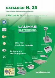
Atrium TSX PCI 57 204M/354M slot PLCs are PC format cards (PCI 32-bit/25…33<br />
MHz bus) to be integrated into a PC running under Windows 2000 or Windows XP.<br />
This combination of PLC and PC optimizes performance in applications requiring, for<br />
example, a higher level of communication, control or supervision functions. The slot<br />
PLC manages the entire PLC station, which comprises the same I/O modules as<br />
<strong>Premium</strong> processors (discrete, analog, application-specific and communication):<br />
b Locally, in one or more racks connected to bus X on the Atrium slot PLC<br />
b Using remote I/O via the same fieldbuses<br />
Two types of Atrium slot PLC are available. They can both accommodate:<br />
b A maximum of 16 extendable TSX RKY ppEX racks<br />
b A CANopen master bus function in their external PCMCIA slot<br />
Both have:<br />
b An internal PCMCIA slot (no. 0) to accommodate all types of memory extension<br />
card: program and symbols only, or mixed (program, symbols and data storage)<br />
b An external PCMCIA slot (no. 1) to accommodate the network card (Fipway,<br />
Modbus Plus) or bus (CANopen, Modbus, Uni-Telway, Fipio Agent and serial link)<br />
This slot can also accommodate the 4 or 8 Mb SRAM memory extension card used<br />
to store additional data (see page 1/22).<br />
Their distinguishing characteristics are:<br />
b The short application program execution time<br />
b The program memory and data memory capacity<br />
b 80 or 128 “in-rack” analog I/O<br />
b 24 or 32 application-specific channels: Each application-specific module (counter,<br />
motion control, serial link, or weighing) accounts for 1 or a number of applicationspecific<br />
channels.<br />
b 1 or 3 networks (Ethernet Modbus/TCP, Fipway, Modbus Plus, Ethway types),<br />
1 Ethernet Modbus/TCP network, 4 or 8 AS-Interface buses V2.1, 1 CANopen bus<br />
and 1 or 3 third-party fieldbuses (InterBus, Profibus DP)<br />
b 10 or 15 process control channels<br />
Integrated communication<br />
Six means of integrated communication (communication that does not require the<br />
external rack to be connected on the slot PLC bus X) are possible:<br />
b CANopen master, via a PCMCIA card that is inserted into the external slot on the<br />
slot PLC<br />
b Fipio manager, via a 9-way SUB-D type connector on the faceplate of the<br />
TSX PCI 57 354M slot PLC<br />
b Ethernet Modbus/TCP, via the TCP/X-Way Windows-compatible gateway<br />
software, which communicates with the slot PLC via the PCI bus on the host PC (this<br />
software is either connected to an Ethernet port in the host PC, integrated into the<br />
motherboard or supplied on a PC format card)<br />
b InterBus master generation 4, via an additional PC format card, occupying an ISA<br />
bus slot and connected to the slot PLC via a ribbon cable that includes bus X<br />
b Modbus Plus or Fipway, via a PCMCIA card that is inserted into the external slot<br />
(no. 1) on the slot PLC<br />
b Communication via a terminal port (TER) using Uni-Telway or character mode<br />
protocol, 19.2 or 115 Kbit/s (typically a programming terminal or an HMI terminal)<br />
9<br />
10<br />
Description:<br />
pages 1/16 …<br />
Memory structure:<br />
pages 1/18 …<br />
Characteristics:<br />
pages 1/20 …<br />
References:<br />
pages 1/21 …<br />
PCMCIA references:<br />
pages 1/22 …<br />
1/14
Presentation (continued)<br />
<strong>Modicon</strong> <strong>Premium</strong><br />
automation <strong>platform</strong><br />
Atrium slot PLCs<br />
Unity<br />
Presentation (continued)<br />
TSX PSI 2010 standalone power supply<br />
In order to enable standalone operation in the event of a PC power outage, a<br />
standalone c 24 V TSX PSI 2010 power supply can be connected to a PCI or ISA<br />
bus slot to ensure continuity of service for the automation part of the system (only<br />
functions managed by the PC are disabled).<br />
Design and installation of Atrium applications<br />
Installation of these new Atrium slot PLCs requires:<br />
b Unity Pro Medium, Large, Extra Large or XL Safety programming software. This is<br />
the same as the software used on the <strong>Modicon</strong> M340 and <strong>Modicon</strong> Quantum<br />
<strong>platform</strong>s.<br />
b Optionally, depending on requirements:<br />
v Unity Application Generator (UAG) specialist software for modeling and<br />
generating process applications<br />
v Unity EFB toolkit software for developing EF and EFB function block libraries in<br />
C language<br />
v Unity SFC View software for displaying and diagnosing applications written in<br />
Sequential Function Chart (SFC) language<br />
The Atrium slot PLC is not supplied with any Windows driver or application type<br />
software programs. These are supplied with the Unity Pro, Vijeo Designer,<br />
Vijeo Citect, OFS (OPC Factory Server), etc. software.<br />
They enable connection to the slot PLC via:<br />
b<br />
b<br />
b<br />
Uni-Telway and the TER port on the front panel<br />
PCIway and the PC host’s PCI bus<br />
Ethernet Modbus/TCP (XIP)<br />
1<br />
2<br />
3<br />
4<br />
Ethernet Modbus/TCP<br />
PC Panel Magelis iPC<br />
fitted with, for example:<br />
- Atrium TSX PCI slot PLC<br />
- Vijeo Designer and Unity Pro software<br />
- TCP/X-Way gateway software<br />
- c 24 V standalone power supply<br />
<strong>Premium</strong> I/O extension racks<br />
Altivar<br />
Momentum<br />
Ethernet, CANopen, Fipio, Modbus Plus, InterBus<br />
Typical architecture<br />
By integrating an Atrium slot PLC card, the architecture shown opposite can be<br />
created using any compatible PC (equipped with PCI bus slots) and PC Panel<br />
Magelis iPC<br />
This solution can provide a PLC architecture in which the I/O are:<br />
b Remotely located close to the machine or process via the fieldbus (1):<br />
v Ethernet Modbus/TCP via the TLX CD GTW 10M gateway software<br />
v CANopen with TSX CPP 110 PCMCIA card<br />
v Fipio with the integrated port on the TSX PCI 57 354M slot PLC<br />
v Modbus Plus with TSX MBP 100 PCMCIA card<br />
v InterBus with PC format slot PLC card, TSX IBX 100 ISA bus (link to<br />
TSX PCI 57 204M/354M slot PLC via ribbon cable)<br />
b And/or centralized in TSX RKY ppEX extendable racks. TSX RKY ppEX<br />
extendable racks connected on bus X permit the use of application-specific modules<br />
and the setting up of AS-Interface bus segments. For example:<br />
v TSX ETY 4103 or TSX ETY 5103 Ethernet Modbus/TCP module (with Web<br />
server, FactoryCast server or TSX WMY 100 module (FactoryCast HMI server)<br />
v InterBus TSX IBY 100 or Profibus DP TSX PBY 100 master module<br />
v TSX SAY 1000 AS-Interface V2.1 master module<br />
v TSX CAY, TSX CFY or TSX CSY 84 (SERCOS) motion control modules.<br />
_________________________________________________________________<br />
(1) Corresponding to an integrated module solution on the host PC, without having to use<br />
modules on extension racks on bus X.<br />
5<br />
6<br />
7<br />
8<br />
9<br />
10<br />
Description:<br />
pages 1/16 …<br />
Memory structure:<br />
pages 1/18…<br />
Characteristics:<br />
pages 1/20 …<br />
References:<br />
pages 1/21 …<br />
PCMCIA references:<br />
pages 1/22 …<br />
1/15
Description<br />
<strong>Modicon</strong> <strong>Premium</strong><br />
automation <strong>platform</strong><br />
Atrium slot PLCs<br />
Unity<br />
1<br />
2<br />
3<br />
4<br />
TSX PCI 57 354M<br />
1<br />
2<br />
3<br />
5<br />
6<br />
4<br />
Description<br />
Atriul slot PLCs<br />
TSX PCI 57 204M/354M slot PLCs mechanically occupy two consecutive slots on<br />
the PCI bus, but only use one electrically (1). They feature:<br />
b On the faceplate:<br />
1 A PCMCIA slot (no.1) for a communication card or memory extension card for<br />
storing additional data<br />
2 A 9-way female SUB-D connector for connecting bus X to the first extendable rack<br />
supporting the I/O modules and application-specific modules<br />
3 An 8-way female mini-DIN connector marked TER for connecting a programming<br />
terminal<br />
4 A RESET button causing a cold restart of the slot PLC when it is activated<br />
5 An ERR lamp (red); fault on the slot PLC or its on-board devices (PCMCIA<br />
memory or communication cards)<br />
6 A 9-pin male SUB-D connector (on TSX PCI 57 354M model) for Fipio bus<br />
manager communication.<br />
b On the components side of the card:<br />
v 4 or 5 LEDs indicating the operating status (RUN, TER, BAT, I/O and FIP on the<br />
TSX PCI 57 354M)<br />
v<br />
v<br />
v<br />
v<br />
A slot for a backup battery for the slot PLC internal RAM memory<br />
A slot (no. 0) for a PCMCIA format memory extension card<br />
A bus X line terminator circuit (type A)<br />
A PCI bus connector for connection to the host PC<br />
Supplied with the slot PLC<br />
1 bus X line terminator (type B) to be installed at the end of the last of the I/O and<br />
application-specific module support racks.<br />
5<br />
7<br />
Description of the additional TSX PCI ACC1 remote bus X faceplate<br />
7 An additional faceplate, TSX PCI ACC1, fitted with a 9-way male SUB-D<br />
connector, enabling the slot PLC Atrium to be located in the middle of its extension<br />
racks rather than at one end of them.<br />
6<br />
7<br />
TSX PCI ACC1<br />
8<br />
9<br />
Description of the c 24 V TSX PSI 2010 power supply<br />
The c 24 V TSX PSI 2010 power supply is inserted into a PCI bus slot located next<br />
to the TSX PCI 57 204M/354M slot PLC. It occupies one slot mechanically but no<br />
slots electrically. It can provide the power supply for one slot PLC.<br />
It features the following on the front panel:<br />
8 A 9-way female SUB-D connector enabling a second remote bus X to be<br />
connected (instead of using the TSX PCI ACC1 faceplate)<br />
9 A 3-way female SUB-D connector for connection to the c 24 V power supply<br />
(male connector supplied)<br />
TSX PSI 2010<br />
This power supply includes two ribbon cables for connection to the slot PLC, one for<br />
the power supply to the slot PLC and the other to ensure bus X continuity.<br />
8<br />
__________________________________________________________________<br />
(1) Atrium slot PLCs can also operate using just one PC slot: For this purpose, carefully unscrew<br />
and remove the external PCMCIA slot.<br />
9<br />
10<br />
Presentation:<br />
pages 1/14…<br />
Memory structure:<br />
pages 1/18 …<br />
Characteristics:<br />
pages 1/20…<br />
References:<br />
pages 1/21 …<br />
PCMCIA references:<br />
pages 1/22 …<br />
1/16
Gateway,<br />
setup<br />
<strong>Modicon</strong> <strong>Premium</strong><br />
automation <strong>platform</strong><br />
Atrium slot PLCs<br />
Unity<br />
PC<br />
SCADA<br />
OFS server<br />
Ethernet Modbus/TCP<br />
1 2<br />
3<br />
Uni-TE<br />
<strong>Premium</strong><br />
Quantum<br />
Modbus<br />
1 Atrium slot PLC<br />
2 Ethernet Modbus/TCP card or integrated port<br />
3 TCP/X-Way software gateway<br />
Magelis iPC or PC with:<br />
- 1 Atrium slot PLC<br />
- and TSX PCI ACC1<br />
faceplate or TSX PSI 2010<br />
power supply<br />
TCP/X-Way gateway<br />
The TCP/X-Way software gateway performs 2 main functions for Atrium slot PLCs:<br />
b Communication using the Modbus or Uni-TE protocol via the Ethernet<br />
Modbus/TCP card integrated in the PC<br />
b Data exchange in both directions with remote stations via the telephone modem in<br />
the PC<br />
This software interfaces with the Atrium slot PLC PCIway driver and automatically<br />
routes messages. The most common configurations are:<br />
v Via Ethernet network (diagram opposite). Access is made secure by checking<br />
incoming IP addresses, in a similar way to the <strong>Premium</strong> PLC Ethernet TSX ETY 4103<br />
module. The Global Data and I/O Scanning services are not supported.<br />
v Via modem link. Incoming calls are checked via the standard Windows password<br />
checking mechanisms. In addition to remote access with Unity Pro software, the<br />
TCP/IP gateway enables communication with other stations that can be connected<br />
to a local Ethernet network (RAS (Remote Access Server) function).<br />
Setup<br />
Integration into the host PC<br />
To receive a TSX PCI 57 204M/354M Atrium slot PLC, the host PC must:<br />
b Run under Windows 2000 or Windows XP<br />
b Have a 33-bit 33 MHz (c 5 V or c 3.3 V) PCI bus<br />
b Have two consecutive slots available on the PCI bus (of which at least one must<br />
be a PCI type slot)<br />
The maximum number of slot PLCs per PC depends on the number of available<br />
PCI/ISA slots, the PC power supply rating (when the TSX PSI 2010 power supply<br />
option is not used) and whether or not PCMCIA cards have been inserted into the<br />
slot PLC.<br />
The slot PLC is completely independent of the application running on the PC, in<br />
particular:<br />
b The standard PC command “Restart” (1) has no effect on the slot PLC operating<br />
modes (2).<br />
b Switching the PC off and then on again causes a warm restart of the application<br />
being managed by the slot PLC (restart without loss of application context).<br />
b The TSX PSI 2010 c 24 V standalone power supply allows the slot PLC to<br />
operate even in the event of a PC power supply outage.<br />
The host PC, equipped with Unity Pro software, can be used as a programming and<br />
setup terminal for the TSX PCI 57 Atrium slot PLC.<br />
Logical location on bus X<br />
The Atrium TSX PCI 57 204M/354M slot PLC logically occupies the same 2 slots as<br />
a <strong>Premium</strong> TSX 57 processor of the same type. The 2 slots in the TSX RKY ppEX<br />
rack with address 0 next to the TSX PSY ppp0M power supply module must<br />
therefore remain unoccupied.<br />
1<br />
2<br />
3<br />
4<br />
5<br />
6<br />
7<br />
TSX RKY ppEX rack<br />
TSX RKY ppEX rack<br />
The TSX PCI ACC1 faceplate or TSX PSI 2010 c 24 V power supply enables a<br />
second bus X to be connected from PC Panel Magelis iPC industrial PCs, thus<br />
forming a Y structure (see the diagram opposite, where the maximum length of each<br />
bus X segment is 100 m).<br />
8<br />
__________________________________________________________________<br />
(1) “Ctrl-Alt-Del” command, followed by “Restart” or pressing the “Reset” button on the PC (if<br />
there is one).<br />
(2) Causes the loss of the PCI bus connection.<br />
9<br />
10<br />
Presentation:<br />
pages 1/14 …<br />
Memory structure:<br />
pages 1/18 …<br />
Characteristics:<br />
pages 1/20 …<br />
References:<br />
pages 1/21…<br />
PCMCIA references:<br />
pages 1/22 …<br />
1/17
Memory structure<br />
<strong>Modicon</strong> <strong>Premium</strong><br />
automation <strong>platform</strong><br />
Atrium slot PLCs<br />
Unity<br />
1<br />
2<br />
Slot PLC without PCMCIA memory card<br />
Located data<br />
Global and DFB<br />
unlocated data<br />
Internal RAM<br />
160 to 208 Kb<br />
Program, symbols and<br />
area for online program<br />
modification<br />
Constants<br />
1<br />
1<br />
2<br />
3<br />
Memory structure<br />
The application memory is divided into memory areas physically distributed in the<br />
internal RAM memory and on 0, 1 or 2 PCMCIA memory extension cards:<br />
1 The application data area, which may be one of 2 possible types, is always in the<br />
internal RAM:<br />
v Located data corresponding to data defined by an address (e.g. %MW237) to<br />
which a symbol may be associated (e.g. Counting_rejects).<br />
v Global unlocated data corresponding to data defined only by a symbol. This type<br />
of addressing removes memory “mapping” management constraints, as address are<br />
assigned automatically, and enables data to be structured.<br />
v DFB unlocated data, corresponding to data from DFB user function blocks. The<br />
size of this object zone is only limited by the size of the physical internal RAM<br />
memory available 1 (160 Kb or 208 Kb).<br />
3<br />
4<br />
Slot PLC with PCMCIA memory card in slot no. 0<br />
Located data<br />
Internal RAM<br />
160 or 208 Kb<br />
Global unlocated data<br />
DFB unlocated data<br />
1<br />
1<br />
1<br />
2 Area in internal RAM or PCMCIA memory card for the program and symbols. In<br />
the event of this area being in internal RAM, it also supports the area for modifying<br />
the program in online mode (1).<br />
This area contains the program’s executable binary code and IEC source code.<br />
The user selects the type of information to be stored in the slot PLC memory.<br />
3 Constants area in the internal RAM or the PCMCIA memory card (slot no. 0)<br />
4 Storage area for additional data (slot no. 0 or no. 1), e.g. for production data and<br />
manufacturing recipes<br />
5<br />
6<br />
7<br />
PCMCIA card<br />
slot no. 0<br />
128 to 7168 Kb<br />
Program and symbols<br />
Constants<br />
Storage of additional<br />
data<br />
2<br />
3<br />
4<br />
Memory organization<br />
Two memory structures are possible depending on whether the Atrium slot PLC is<br />
fitted with 0, 1 or 2 memory extension cards:<br />
b Application in internal RAM. In this case, the application is entirely loaded in the<br />
PLC slot’s internal battery-backed RAM (2), the capacity of which depends on the<br />
PLC slot model (160 Kb or 208 Kb).<br />
b Application in PCMCIA card. In this case, the internal RAM is reserved for<br />
application data. The PCMCIA memory card (slot no. 1) contains the program space<br />
(program, symbols and constants areas) (768 Kb or 1792 Kb).<br />
Certain types of PCMCIA memory card host the data storage area (max. 6976 Kb).<br />
Symbols areas<br />
The presence of the symbols area with the program area is optional. Having the<br />
application symbols database on the memory of the slot PLC means that, when<br />
connected to a programming terminal not containing any applications all the<br />
elements needed to debug or upgrade this PLC are available within the PLC.<br />
__________________________________________________________________<br />
(1) If a PCMCIA card has been inserted, the memory used by program modification in online<br />
mode is located in this memory card (outside zones 2, 3 and 4 opposite).<br />
(2) The internal RAM memory is backed up by an optional battery (3 years’ battery life) located in<br />
the power supply module (see page 2/2).<br />
8<br />
9<br />
10<br />
1<br />
1<br />
2<br />
Presentation:<br />
pages 1/14…<br />
Description:<br />
pages 1/16 …<br />
Characteristics:<br />
pages 1/20…<br />
References:<br />
pages 1/21 …<br />
PCMCIA references:<br />
pages 1/22 …<br />
1/18<br />
3
Memory structure (continued)<br />
<strong>Modicon</strong> <strong>Premium</strong><br />
automation <strong>platform</strong><br />
Atrium slot PLCs<br />
Unity<br />
Slot PLC with data storage memory card in slot no. 0<br />
Located data<br />
Internal RAM<br />
Global and DFB<br />
unlocated data<br />
Program, symbols and<br />
area for online program<br />
modification<br />
Constants<br />
PCMCIA data<br />
storage card (slot<br />
no. 0)<br />
Storage of additional<br />
data<br />
160 or 208 Kb<br />
4096 or 8192 Kb<br />
1<br />
1<br />
2<br />
3<br />
4<br />
Memory structure (continued)<br />
Extension of the data storage area<br />
Memory cards reserved for data storage (4096 or 8192 Kb) are used to:<br />
b Access the data storage area when the application is entirely supported by the<br />
internal RAM. In this case, the data storage memory card is inserted into PCMCIA<br />
slot no. 0.<br />
b Free up memory space to provide additional program space when the application<br />
is in the PCMCIA card (slot no. 0). In this case, the data storage memory card is<br />
inserted into PCMCIA slot no. 1 (a part of it can be supported by the memory card in<br />
the slot).<br />
Unity Pro programming software assists the application designer with the<br />
management of the structure and the occupation of memory space on the<br />
Atrium slot PLC.<br />
Protecting the application<br />
Regardless of the slot PLC memory structure (whether the application is located in the<br />
internal RAM or in the PCMCIA memory card), it is possible to protect this in order to<br />
prevent it being accessed (read or modify program) by only loading the executable<br />
code on the slot PLC.<br />
1<br />
2<br />
3<br />
Slot PLC with mixed type memory cards in slot no. 0 and data<br />
storage type memory cards in slot no. 1<br />
Internal RAM<br />
PCMCIA card (slot<br />
no. 0)<br />
PCMCIA data<br />
storage card (slot<br />
no. 1)<br />
160 or 208 Kb<br />
128 to 7168 Kb<br />
4096 or 8192 Kb<br />
Located data<br />
1<br />
Global unlocated data<br />
1<br />
Unlocated DFB data<br />
1<br />
Program and symbols<br />
2<br />
Constants<br />
3<br />
Additional data storage<br />
(zone A)<br />
4<br />
Additional data storage<br />
4<br />
(zone B)<br />
A memory protection bit, set in configuration mode, is also available to prevent any<br />
program modification (via the programming terminal or downloads).<br />
Program modification in online mode<br />
This function is different from previous versions of <strong>Premium</strong> PLCs (with PL7<br />
software) and now allows program code and data in different parts of the application<br />
to be added or modified in a single modification session (thus making modification<br />
unified and consistent with regard to the controlled process).<br />
This increased flexibility comes at a cost in terms of the program memory volume<br />
required. Any program modifications made in online mode require available program<br />
memory space at least equal in size to the combined size of all sections of the<br />
Unity Pro program affected by the same modification session.<br />
Depending on circumstances:<br />
b For a slot PLC with memory extension card, the memory volume remaining<br />
available in the card for online modification is sufficient if the recommendations on<br />
page 1/22 are observed.<br />
b For a slot PLC without memory extension card, users wishing to have the option of<br />
making modifications in online mode may select a processor according to:<br />
v The anticipated size of the application<br />
v The number and size of the program sections to be modified in online mode<br />
Note: A memory extension card that only uses Flash Eprom technology (without additional<br />
SRAM) cannot provide the function of program modification in online mode.<br />
4<br />
5<br />
6<br />
7<br />
8<br />
9<br />
10<br />
Presentation:<br />
pages 1/14 …<br />
Description:<br />
pages 1/16 …<br />
Characteristics:<br />
pages 1/20 …<br />
References:<br />
pages 1/21 …<br />
PCMCIA references:<br />
pages 1/22 …<br />
1/19
Characteristics<br />
<strong>Modicon</strong> <strong>Premium</strong><br />
automation <strong>platform</strong><br />
Atrium slot PLCs<br />
Unity<br />
1<br />
2<br />
3<br />
4<br />
5<br />
6<br />
7<br />
8<br />
9<br />
10<br />
Characteristics and performance<br />
Type of processor TSX PCI P57 204M TSX PCI P57 354M<br />
Maximum No. of racks 4/6/8 slots 16<br />
configuration<br />
12 slots 8<br />
Max. no. of slots for modules 128<br />
Functions<br />
Memories<br />
Application<br />
structure<br />
Execution<br />
time for one<br />
instruction<br />
Max. no. “in<br />
rack” of (1)<br />
Integrated Ethernet<br />
connections<br />
Maximum<br />
no. of<br />
connections<br />
Maximum<br />
capacity<br />
Maximum<br />
size of<br />
object<br />
zones<br />
Discrete I/O 1024<br />
Analog I/O 80 128<br />
Process control channels 10 (up to 30 simple loops) 15 (up to 60 simple loops)<br />
Programmable loops via EFB control blocks (with Unity Pro Large and Extra Large)<br />
No. of applic.-specific ch. 24 32<br />
Type of applic.-specific ch.<br />
Counter, axis, weighing and serial links (Modbus, Uni-Telway and asynchronous)<br />
1 (uses the Ethernet Modbus/TCP port integrated in the host PC via the TLX CD GTW 10M<br />
gateway software)<br />
Fipio manager – 1 (127 agents)<br />
Serial link<br />
1 link with 2 connectors (TER and AUX) 1 link with 2 connectors (TER and AUX),<br />
19.2 Kbit/s<br />
19.2 or 115 Kbit/s<br />
Network<br />
(Ethernet, Fipway, Ethway,<br />
Modbus Plus)<br />
2 (including 1 Ethernet Modbus/TCP<br />
integrated into host PC)<br />
4 (including 1 Ethernet Modbus/TCP<br />
integrated into host PC)<br />
AS-Interface bus 4 8<br />
CANopen or Modbus Plus bus 1<br />
InterBus or Profibus DP bus 1, none if CANopen is used 3, 2 if CANopen is used<br />
Without PCMCIA card Kb 160 program + data 208 program + data<br />
With PCMCIA card Kb 768 program<br />
160 data<br />
1792 program<br />
208 data<br />
Data storage Kb 16,384 (limited to 8192 with current PCMCIA cards)<br />
Located internal bits (% Mi) bit/s 8132 16,384<br />
Located internal data Kb 64 for internal words %MpWi, 64 for constant words %KpWi<br />
Global unlocated internal data Kb Elementary EDT and derived DDT data: 64 Kb<br />
DFB and EFB function blocks: size per instance 64 Kb, unlimited number of instance (within the<br />
limits of slot PLC’s data memory capacity)<br />
Tasks Master 1<br />
Fast 1<br />
Auxiliary –<br />
Evens<br />
64 (1 of which has priority)<br />
Without<br />
PCMCIA<br />
card<br />
With<br />
PCMCIA<br />
card<br />
Typical program code<br />
execution time for<br />
1 Kinstruction<br />
System<br />
overhead<br />
Boolean ms 0.19 0.12<br />
On word or fixed-point ms 0.25 0.17<br />
arithmetic<br />
On floating points ms 1.75...2.60 (2)<br />
Boolean ms 0.21 0.17<br />
On word or fixed-point ms 0.42 0.32<br />
arithmetic<br />
On floating points ms 1.75...2.60 (2)<br />
100% Boolean Kinst/ 4.76/ 3.70 (3) 6.72/4.59 (3)<br />
ms<br />
65% Boolean and 35% fixed Kinst/ 3.71/2.53 (3) 5.11/3.12 (3)<br />
arithmetic<br />
ms<br />
Tasks Master ms 1.00 1.00<br />
Fast ms 0.30 0.25<br />
(1) Only affects “in-rack” modules. The maximum values for the number of discrete I/O, analog I/O and application-specific channels are cumulative. The remote I/O<br />
on the bus or network (CANopen, AS-Interface/Uni-Telway/Fipio/Modbus Plus, etc.) or third-party bus (InterBus or Profibus DP) are not included in this<br />
maximum number.<br />
(2)Values limited according to the type of instruction<br />
(3)The first value corresponds to execution time without PCMCIA card and the second value with PCMCIA card.<br />
Standalone power supply characteristics<br />
Type of power supply module TSX PSI 2010<br />
Primary Voltage Nominal V c 24<br />
Limits (including ripple) V c 19.2 … 30 (possible up to 36 V)<br />
Current Nominal input value 1 rms A y 1.1 at c 24 V<br />
Initial powerup<br />
at 25°C<br />
1 inrush A 100 at c 24 V<br />
I 2 t on triggering A 2 3<br />
It on triggering As 0.04<br />
Power line disturbance period ms y 7 at 24 V, y 1 at 19.2 V<br />
Built-in protection<br />
Via a 2 A time-delay fuse (complying with standards)<br />
Conformity to standards IEC 1131-2<br />
Insulation<br />
Dielectric<br />
strength<br />
Primary/secondary and<br />
primary/earth<br />
V rms<br />
Non-isolated, internal 0 V connected to PC ground<br />
1/20
References<br />
<strong>Modicon</strong> <strong>Premium</strong><br />
automation <strong>platform</strong><br />
Atrium slot PLCs<br />
Unity<br />
TSX PCI 57 204M<br />
Atrium slot PLCs<br />
I/O capacity (1) Capacities Maximum number<br />
Memory<br />
Process control<br />
channels<br />
of bus/network<br />
modules<br />
TSX PCI 57 20 16 racks (2)<br />
1024 discrete I/O<br />
80 analog I/O<br />
24 application-specific<br />
channels<br />
160 Kb integrated<br />
Max. 768 Kb on<br />
PCMCIA<br />
10 1 network all types<br />
1 Ethernet network<br />
4 AS-Interface<br />
buses<br />
1 CANopen bus (3)<br />
1 fieldbus (3)<br />
Reference<br />
Weight<br />
kg<br />
TSX PCI 57 204M 0.310<br />
1<br />
2<br />
TSX PCI 57 35 16 racks (2)<br />
1024 discrete I/O<br />
128 analog I/O<br />
32 application-specific<br />
channels<br />
208 Kb integrated<br />
Max. 1792 Kb on<br />
PCMCIA<br />
15 1 integrated Fipio<br />
3 networks all types<br />
1 Ethernet network<br />
8 AS-Interface<br />
buses<br />
1 CANopen bus (3)<br />
3 third-party buses<br />
(3)<br />
TSX PCI 57 354M 0.340<br />
3<br />
TSX PCI 57 354M<br />
PCMCIA memory extension cards<br />
Atrium slot PLCs can support up to 2 memory extension cards. However, useful memory capacity is limited to the maximum<br />
size defined for the slot PLC model.<br />
References, see pages 1/22 and 1/23.<br />
4<br />
TSX PCI ACC1<br />
Software options (4)<br />
When connected to an Atrium slot PLC, the TCP/X-Way gateway software offer (supplied on CD-ROM) enables<br />
communication under the Modbus or Uni-TE protocol using the Ethernet Modbus/TCP port integrated into the host PC.<br />
Description Use Site license Reference Weight<br />
kg<br />
TCP/X-Way gateway<br />
software<br />
Compatible with Windows 2000 or XP Single-station TLX CD GTW 10M –<br />
Separate parts<br />
Description Use Sold in lots of Reference Weight<br />
kg<br />
Faceplate for remote bus X Enables a second remote<br />
bus X connection (9-way SUB-D<br />
connector)<br />
– TSX PCI ACC1 –<br />
c 24 V standalone power<br />
supply<br />
Enables the TSX PCI slot PLC to operate in<br />
the event of a PC power supply outage<br />
Enables a second remote bus X connection<br />
(9-way SUB-D connector)<br />
– TSX PSI 2010 –<br />
Batteries Internal RAM memory of slot PLC backup 1 TSX PLP 01 0.010<br />
10 TSX PLP 101 0.100<br />
5<br />
6<br />
7<br />
8<br />
TSX PSI 2010<br />
(1) Cumulative maximum values. The number of remote I/O on the bus is not counted.<br />
(2) Maximum number of TSX RKY 4EX/6EX/8EX racks (4, 6 or 8 slots). Using the TSX RKY 12 EX rack with 12 slots is the<br />
same as using 2 racks with 4, 6 or 8 slots.<br />
(3) Fieldbus: InterBus or Profibus DP.<br />
(4) Other software compatible with Atrium slot PLCs: OFS data server software, see page 6/105;<br />
Vijeo Designer/Vijeo Citect supervisory software, see our catalog “Human/Machine Interfaces”.<br />
9<br />
10<br />
Presentation:<br />
pages 1/14 …<br />
Description:<br />
pages 1/16 …<br />
Memory structure:<br />
pages 1/18 …<br />
Characteristics:<br />
pages 1/20 …<br />
PCMCIA references:<br />
pages 1/22 …<br />
1/21
Presentation<br />
<strong>Modicon</strong> <strong>Premium</strong> automation<br />
<strong>platform</strong><br />
PCMCIA memory extension cards<br />
Unity<br />
1<br />
2<br />
3<br />
4<br />
5<br />
6<br />
7<br />
8<br />
9<br />
10<br />
PCMCIA SRAM memory card<br />
PCMCIA SRAM memory card<br />
<strong>Premium</strong> processors<br />
Atrium slot PLCs<br />
Cards recommended for program modification<br />
in online mode<br />
TSX P57 Cp<br />
TSX P57 0p<br />
All<br />
TSX MRP PpppK<br />
and TSX MRP<br />
CpppK/M/7<br />
Presentation<br />
PCMCIA memory extension cards are used to extend the internal RAM capacity of<br />
<strong>Premium</strong> processors and Atrium slot PLCs.<br />
Some of the cards can also be used on Quantum and Micro processors. Depending<br />
on the model, these cards can host:<br />
b Application program, symbols and constants<br />
b Additional application data<br />
b Or both<br />
PCMCIA memory extension cards<br />
All the cards are inserted into PCMCIA slot no. 0 on <strong>Premium</strong> processors and Atrium<br />
slot PLCs, i.e.:<br />
b<br />
b<br />
The upper slot on processors<br />
The internal slot on slot PLCs<br />
Two of these SRAM data storage memory cards can also be inserted into slot no. 1,<br />
i.e.:<br />
b The lower slot on processors<br />
b The external slot on slot PLCs<br />
These cards support three types of data storage:<br />
b Application storage: Program, symbols and constants in a common space (128 Kb<br />
to 7168 Kb, depending on the card model):<br />
v TSX MRP PpppK for SRAM memories<br />
v TSX MFP PpppK/M for Flash EPROM memories<br />
b Storage of the application and additional data, with 192 Kb to 7 Mb of application<br />
space and 7 Mb to 0 Kb of data storage space for additional data. The limit between<br />
these 2 spaces is configurable. The configurable cards are:<br />
v TSX MRP CpppK/M for SRAM memories<br />
v TSX MCP CpppK/M for Flash EPROM and SRAM memories<br />
b Storage of additional data, provided by 4 Mb or 8 Mb TSX MRP F00pM SRAM<br />
memory cards<br />
These cards use 2 technologies:<br />
b Battery-backed SRAM<br />
Used in particular in the creation and debugging phases for the application program.<br />
These cards support:<br />
v All of the application’s transfer and modification services in online mode<br />
v Additional data storage<br />
The memory is backed up by a removable battery integrated into the PCMCIA card.<br />
A second auxiliary battery is present to enable the main battery to be replaced<br />
without loss of data.<br />
b Flash EPROM<br />
Used once debugging of the application program is complete. It enables:<br />
v Backup battery life restrictions to be overcome<br />
v A global application transfer to be performed<br />
If it is used, the application cannot be modified in online mode.<br />
Program modification in online mode<br />
Only extension cards on which the program is stored in SRAM memory<br />
(TSX MRP PpppK/M. and TSX MRP CpppK/M) support online program<br />
modification.<br />
Users of processors fitted with memory extension cards who wish to modify or add<br />
program data in online mode must follow the two recommendations below:<br />
b Structure the application program in a number of sections of a reasonable size<br />
b Where possible, select one of the two extension cards recommended in the table<br />
below:<br />
TSX P57 1p<br />
TSX MRP<br />
P224K/P384K,<br />
all TSX MRP<br />
CpppK/M/7<br />
TSX P57 2p<br />
TSX PCI 57 2p<br />
TSX P57 3p<br />
TSX PCI 57 3p<br />
All TSX MRP CpppK/M/7<br />
TSX P57 4p TSX P57 5p TSX P57 6p<br />
TSX MRP C002M, TSX MRP C003M,<br />
TSX MRP C007M<br />
1/22
References<br />
<strong>Modicon</strong> <strong>Premium</strong> automation<br />
<strong>platform</strong><br />
PCMCIA memory extension cards<br />
Unity<br />
Reminder of the memory capacities of processors and slot PLCs<br />
Memory capacities without PCMCIA extension card (data, program, symbols, and constants in internal RAM memory):<br />
<strong>Premium</strong> processors<br />
Atrium slot PLCs<br />
TSX P57<br />
Cp0244/<br />
0244M<br />
TSX P57<br />
104/154M/<br />
1634M<br />
TSX 57<br />
204/<br />
2634M<br />
TSX PCI<br />
57 204M<br />
TSX P57<br />
254<br />
TSX P57<br />
304/<br />
3634M<br />
TSX P57<br />
354M<br />
TSX PCI<br />
57 354M<br />
TSX P57<br />
454/<br />
4634M<br />
TSX P57<br />
554/<br />
5634M<br />
TSX P57<br />
6634M<br />
In internal RAM 96 Kb 160 Kb 192 Kb 208 Kb 440 Kb 1024 Kb 2048 Kb<br />
Memory capacities with PCMCIA extension card(s) (data in internal RAM memory; program, symbols, constants, and data storage on PCMCIA card):<br />
<strong>Premium</strong> processors<br />
Atrium slot PLCs<br />
TSX P57<br />
0244M<br />
TSX PCI<br />
57 204M<br />
TSX P57<br />
254<br />
TSX P57<br />
354M<br />
TSX PCI<br />
57 354M<br />
TSX P57<br />
6634M<br />
TSX P57<br />
104/154M/<br />
1634M<br />
TSX 57<br />
204/<br />
2634M<br />
TSX P57<br />
304/<br />
3634M<br />
TSX P57<br />
454/<br />
4634M<br />
TSX P57<br />
554/<br />
5634M<br />
Data in internal RAM 96 Kb 160 Kb 192 Kb 208 Kb 440 Kb 1024 Kb 2048 Kb<br />
PCMCIA extension (progr., 128 Kb 224 Kb 768 Kb 768 Kb 1792 Kb 1792 Kb 2048 Kb 7168 Kb 7168 Kb<br />
symbols and constants)<br />
Data storage on PCMCIA (1) 256 Kb<br />
16,384 Kb, limited to 8192 Kb if the TSX MRP F008M PCMCIA card is used<br />
PCMCIA memory extension cards<br />
<strong>Premium</strong> TSX P57 Cp/0p/1p/2p/3p/4p/5p/6p processors and Atrium TSX PCI 57 2p/3p slot PLCs support the memory extension<br />
cards listed below. There are two types of memory limit:<br />
- One associated with the type of processor or slot PLC (see above)<br />
- One associated with the model of PCMCIA memory card selected<br />
The lowest of these two limits defines the memory capacity available to the user for his/her application.<br />
Use on processor Slot Memory size Reference Weight<br />
Application<br />
Additional data<br />
kg<br />
SRAM application memory extensions<br />
TSX 57 Cp, TSX 57 0p…57 4p Slot 0 128 Kb – TSX MRP P128K 0,076<br />
TSX PCI 57 2p/3p<br />
224 Kb – TSX MRP P224K 0,076<br />
384 Kb – TSX MRP P384K 0,076<br />
Configurable SRAM application/additional data memory extensions<br />
TSX 57 Cp, TSX 57 0p…57 4p<br />
TSX PCI 57 2p/3p<br />
Slot 0 96…448 Kb 352…0 Kb TSX MRP C448K 0,076<br />
TSX 57 Cp TSX 57 0p…57 6p Slot 0 192…768 Kb 576…0 Kb TSX MRP C768K 0,076<br />
TSX PCI 57 2p/3p<br />
192…1024 Kb 832…0 Kb TSX MRP C001M 0,076<br />
192…1792 Kb 1600…0 Kb TSX MRP C01M7 0,076<br />
192…2048 Kb 1856…0 Kb TSX MRP C002M 0,076<br />
192…3072 Kb 2880…0 Kb TSX MRP C003M 0,076<br />
192…7168 Kb 6976…0 Kb TSX MRP C007M 0,076<br />
Flash EPROM application memory extensions<br />
TSX 57 Cp, TSX 57 0p…57 4p<br />
TSX PCI 57 2p/3p<br />
TSX 57 Cp, TSX 57 0p…57 6p<br />
TSX PCI 57 2p/3p<br />
Slot 0 128 Kb – TSX MFP P128K 0,044<br />
224 Kb – TSX MFP P224K 0,044<br />
384 Kb – TSX MFP P384K 0,044<br />
Slot 0 512 Kb – TSX MFP P512K 0,044<br />
1024 Kb – TSX MFP P001M 0,044<br />
TSX 57 2p…57 6p<br />
Slot 0 2048 Kb – TSX MFP P002M 0,044<br />
TSX PCI 57 2p/3p<br />
4096 Kb – TSX MFP P004M 0,044<br />
Flash EPROM and SRAM application/additional data memory extensions<br />
TSX 57 0p…57 4p<br />
TSX PCI 57 2p/3p<br />
Slot 0 224 Kb 256 Kb TSX MCP C224K 0,076<br />
TSX 57 Cp<br />
TSX 57 0p…57 6p<br />
TSX PCI 57 2p/3p<br />
SRAM additional data memory extensions<br />
TSX 57 2p…57 6p<br />
TSX PCI 57 2p/3p<br />
Slot 0 512 Kb 512 Kb TSX MCP C512K 0,076<br />
2048 Kb 1024 Kb TSX MCP C002M 0,076<br />
Slot 0 or 1<br />
(2)<br />
– 4096 Kb TSX MRP F004M 0,076<br />
8192 Kb TSX MRP F008M 0,076<br />
Flash EPROM backup card (3)<br />
TSX 57 Cp Slot 0 96 Kb – TSX MFP B096K –<br />
TSX 57 0p/1p<br />
Replacement parts<br />
Description Use Type Reference Weight<br />
kg<br />
Backup batteries PCMCIA SRAM memory card Main TSX BAT M02 (4) 0.010<br />
Auxiliary TSX BAT M03 0 005<br />
Handle<br />
Remove PCMCIA memory card – TSX P CAP 0.010<br />
(provided with the memory card)<br />
(1) Intended for the storage of manufacturing recipes and production data. Capacity depending on PCMCIA card model.<br />
(2) Memory extension card for file storage to be inserted into slot no. 0 if free, otherwise into slot no. 1. In the latter case, an<br />
application memory type or application memory and file storage type memory extension card is inserted into slot no. 0.<br />
(3) This card is pre-loaded and can be used to update the application program on a <strong>Premium</strong> PLC without having to use a<br />
programming terminal (the entire program must be located in the internal RAM).<br />
(4) TSX BAT M02 with PCMCIA card PV u 04 (blue), for PCMCIA card PV < 04, please order TSX BAT 01 reference.<br />
1<br />
2<br />
3<br />
4<br />
5<br />
6<br />
7<br />
8<br />
9<br />
10<br />
1/23
Selection guide<br />
<strong>Modicon</strong> <strong>Premium</strong><br />
automation <strong>platform</strong><br />
<strong>Premium</strong> processors<br />
PL7<br />
<strong>Premium</strong>/Atrium <strong>platform</strong>s for PL7 software offer TSX 57 1p processors TSX 57 2p processors<br />
1<br />
2<br />
3<br />
4<br />
5<br />
6<br />
7<br />
8<br />
9<br />
10<br />
Number of racks (according to rack type) 4 with 4, 6, or 8 slots or 2 with 12 slots 16 with 4, 6, or 8 slots or 8 with 12 slots<br />
In-rack I/O (1) Discrete I/O 512 channels (8-, 16-, 32- or 64-channel<br />
modules)<br />
In-rack applicationspecific<br />
channels<br />
1024 channels (8-, 16-, 32- or 64-channel<br />
modules)<br />
Analog I/O 24 channels (4-, 8- or 16- channel modules) 80 channels (4-, 8- or 16- channel modules)<br />
Integrated process control – Configurable loops (10 channels with 3 loops<br />
max.)<br />
Max. no. of channels 8 24<br />
Counter<br />
Modules with 2/4 counter channels 1 MHz max., single-channel electronic cam module<br />
Motion (2)<br />
Modules with 1/2 axes for stepper motors, 2/3/4 axes for analog control servo motors, 8/16 axes<br />
with SERCOS digital link<br />
Weighing<br />
Module for 8 load cells (2 application-specific channels)<br />
Serial links<br />
In-rack communication modules (1 application-specific channel)<br />
Serial link connections Modbus RS 232, RS 485 or current loop (3) (4) master/slave PCMCIA modules and RS 485 master/<br />
slave in-rack communication modules<br />
Uni-Telway<br />
1 integrated RS 485 master/slave channel, RS 232, RS 485 or current loop (3) (4) master/slave<br />
PCMCIA modules and RS 485 master/slave in-rack communication modules<br />
Character mode<br />
1 integrated RS 485 channel, RS 232, RS 485 or current loop (3) (4) PCMCIA modules and<br />
RS 485 in-rack communication modules<br />
Bus connections Actuator/sensor bus<br />
2 in-rack modules 4 in-rack modules<br />
AS-Interface master V2<br />
CANopen machine bus master 1 PCMCIA module (3)<br />
V4.02 (5)<br />
InterBus fieldbus master V2 (5) or – 1 in-rack module<br />
Profibus DP fieldbus master V0<br />
Class 1 and 2 (5)<br />
Network connections Max. no. of networks 1 1<br />
Ethernet<br />
Multiprotocol in-rack modules (Modbus/TCP, Uni-TE, Global Data, I/O Scanning, TCP Open),<br />
Web server, FactoryCast service and FactoryCast HMI services<br />
Network modules<br />
Fipway (3) (4) and Modbus Plus (3) PCMCIA modules, Ethway in-rack modules<br />
Memory capacity Without PCMCIA extension 32 Kwords program and data 48/64 Kwords program and data (6)<br />
With PCMCIA extension<br />
32 Kwords data<br />
64 Kwords program<br />
48/64 Kwords data (6)<br />
160 Kwords program<br />
Data storage 128 Kwords 640 Kwords + 2048 Kwords<br />
Symbol storage – 128 Kwords<br />
Power supply<br />
100…240 V a, 24 V c non-isolated and 24…48 V c isolated power supply modules. A power<br />
supply is required for each rack.<br />
<strong>Premium</strong> processor Standard TSX P57 103M TSX P57 203M Q<br />
Integrated Ethernet TSX P57 2623M Q (8)<br />
Integrated Fipio TSX P57 153M (7) TSX P57 253M Q<br />
Integrated Ethernet and Fipio TSX P57 2823M (8)<br />
Pages 1/31<br />
(1) The maximum values for the numbers of discrete I/O, analog I/O and process control channels are cumulative.<br />
(2) 1 axis = 1 application-specific channel, except for SERCOS modules where, depending on the configuration, the module = 2…32 channels.<br />
(3) Module to be inserted into the lower PCMCIA slot (no. 1) on the processor.<br />
(4) Module to be inserted into the PCMCIA slot on the TSX SCY 21 601 in-rack communication module.<br />
(5) Reduce the number of InterBus or Profibus DP modules permitted by 1 when CANopen is used.<br />
(6) The second value corresponds to the processor with integrated Fipio bus manager link.<br />
1/24
TSX 57 3p processors<br />
TSX 57 4p processors<br />
1<br />
2<br />
n<br />
16 with 4, 6, or 8 slots or 8 with 12 slots<br />
3<br />
1024 channels (8-, 16-, 32- or 64-channel modules)<br />
128 channels (4-, 8- or 16- channel modules)<br />
Configurable loops (15 channels with 3 loops max.)<br />
32 64<br />
Modules with 2/4 counter channels 1 MHz max., single-channel electronic cam module<br />
Modules with 1/2 axes for stepper motors, 2/3/4 axes for analog control servo motors, 8/16 axes with SERCOS digital link<br />
Module for 8 load cells (2 application-specific channels)<br />
In-rack communication modules (1 application-specific channel)<br />
RS 232, RS 485 or current loop (3) (4) master/slave PCMCIA modules and RS 485 master/slave in-rack communication modules<br />
1 integrated RS 485 master/slave channel, RS 232, RS 485 or current loop (3) (4) master/slave PCMCIA modules and RS 485 master/slave in-rack<br />
communication modules<br />
1 integrated RS 485 channel, RS 232, RS 485 or current loop (3) (4) PCMCIA modules and RS 485 in-rack communication modules<br />
4<br />
5<br />
8 in-rack modules<br />
1 PCMCIA module (3)<br />
6<br />
2 in-rack modules<br />
3 4<br />
Multiprotocol in-rack modules (Modbus/TCP, Uni-TE, Global Data, I/O Scanning, TCP Open), Web server, FactoryCast service and FactoryCast HMI services<br />
Fipway (3) (4) and Modbus Plus (3) PCMCIA modules, Ethway in-rack modules<br />
64/80 Kwords program and data (6) 96 Kwords program and data<br />
80/96 Kwords data (6)<br />
384 Kwords program<br />
176 Kwords data<br />
512 Kwords program (992 Kwords with PL7 V4.4 or higher)<br />
640 Kwords + 2048 Kwords 2048 Kwords (640 Kwords + 2048 Kwords with PL7 V4.4 or higher)<br />
128 Kwords 256 Kwords (384 Kwords with PL7 V4.4 or higher)<br />
100…240 V a, 24 V c non-isolated and 24…48 V c isolated power supply modules. A power supply is required for each rack.<br />
7<br />
8<br />
TSX P57 303AM Q<br />
TSX P57 3623AM Q (8)<br />
TSX P57 353LAM (9) TSX P57 353AM Q TSX P57 453AM<br />
1/31<br />
(7) The TSX P57 153M processor does not support the CANopen bus PCMCIA module.<br />
(8) The integrated Ethernet port requires one of the available network connections.<br />
(9) Processor reserved for updating configuration with TSX P57351M/352M PL7 processor (old version)<br />
TSX P57 4823AM (8)<br />
9<br />
Q Processor can be migrated from PL7 to Unity Pro by means of a simple update of the processor's operating system (included on the Unity Pro software<br />
CD-ROM).<br />
n New feature<br />
10<br />
1/25
Presentation<br />
<strong>Modicon</strong> <strong>Premium</strong><br />
automation <strong>platform</strong><br />
PL7 processors<br />
1<br />
Presentation<br />
<strong>Premium</strong> TSX P57 pp3M/3AM and TSX P57 pp23M/23AM automation <strong>platform</strong><br />
processors manage the entire PLC station comprising discrete I/O modules,<br />
Preventa safety modules, analog I/O modules, and application-specific modules,<br />
which can be distributed over one or more racks connected via Bus X or a fieldbus.<br />
TSX P57 processors<br />
2<br />
3<br />
The types of processor available are divided into different capacities according to<br />
memory, in-rack I/O, communication, and processing speed. According to the model:<br />
b 4 to 16 racks<br />
b 512 to 2040 discrete I/O<br />
b 24 to 256 analog I/O<br />
b 8 to 64 application-specific channels: Each application-specific module (counter,<br />
motion control, serial link or weighing) accounts for 1 or a number of applicationspecific<br />
channels.<br />
b 1 to 4 networks (Ethernet, Fipway, Ethway, Modbus Plus), 2 to 8 AS‐Interface<br />
sensor/actuator buses, 1 to 2 fieldbuses (CANopen, InterBus, Profibus DP), 0 or 1<br />
Fipio fieldbus, serial links (Modbus, Uni-Telway)<br />
b 10 to 20 process control channels<br />
Integrated communication<br />
4<br />
5<br />
6<br />
According to the model, <strong>Premium</strong> processors include:<br />
b A 10 or 100 Mbit/s Ethernet Modbus/TCP port (RJ45 connection)<br />
b A 1 Mbit/s Fipio bus link (bus manager)<br />
b Communication via 2 terminal ports (TER and AUX) using Uni-Telway or character<br />
mode protocol (typically a 19 or 115 Kbit/s programming terminal and an operator<br />
dialogue terminal)<br />
Each processor has a slot for a type III PCMCIA card, which can accommodate a<br />
network card (Fipway, Modbus Plus), bus (CANopen (1), Fipio Agent) or serial links<br />
(Modbus, Uni-Telway, character mode).<br />
Application design and installation<br />
Different software licences are available for PL7 Junior/Pro version V4.5 depending<br />
on requirements:<br />
b Single-station<br />
b Multistation in the form of independent local stations (Junior/Pro), remote stations<br />
connected to a server via a network (Pro OpenTeam for 3 to10 stations or<br />
Pro OpenSite for more than 10 stations).<br />
These licences are compatible with PC terminals running Windows 2000<br />
Professional or Windows XP operating systems.<br />
Configurations with TSX P57 351/352M processor or Atrium slot PLC<br />
7<br />
The TSX P57 353LAM single-format processor is intended as a replacement for the<br />
old version TSX P57 351M/352M processors and for T PCX 57 203/353M Atrium<br />
slot PLCs. The latter also only occupy one slot; hence there is no need for<br />
reconfiguration when they are replaced.<br />
Migration of <strong>Premium</strong> processors<br />
8<br />
9<br />
Some <strong>Premium</strong> TSX P57 pp3M/3AM processors that are compatible with PL7<br />
software can be migrated for compatibility with the Unity Pro software without the<br />
need for hardware modifications. This migration from PL7 to Unity Pro is achieved by<br />
means of the following software updates:<br />
b<br />
Processor operating system<br />
Integrated Ethernet port operating system<br />
b<br />
This update is carried out using the OS-Loader tool, included in Unity Pro (see page<br />
6/27). Once migrated, PL7 processors are equivalent to corresponding Unity<br />
processors.<br />
The following PL7 processors can be migrated to Unity Pro (software migration):<br />
b TSX 57 2p: TSX P57 203/253/2623M become<br />
TSX P57 204/254/2634M respectively.<br />
b TSX 57 3p: TSX P57 303/353/3623AM become<br />
TSX P7 304/354/3634M respectively (migration supported by Unity Pro version u 3.0).<br />
10<br />
Note: Processor migration requires the use of new PCMCIA TSX MRP P/C, TSX MFP P/C<br />
memory references. See the equivalence table on page 1/32.<br />
___________________________________________________________________________<br />
(1) Not with TSX P57 153M processor.<br />
Description:<br />
page 1/27<br />
Characteristics:<br />
pages 1/28 ...<br />
Functions:<br />
page 1/30<br />
References:<br />
pages 1/30 ...<br />
1/26
Presentation (continued),<br />
description<br />
<strong>Modicon</strong> <strong>Premium</strong><br />
automation <strong>platform</strong><br />
PL7 processors<br />
TSX P57 1p3M<br />
1<br />
2<br />
3<br />
4<br />
5<br />
6<br />
7<br />
1<br />
2<br />
3<br />
4<br />
5<br />
6<br />
7<br />
TSX P57 2p3M TSX P573p3AM/453AM<br />
1 2 1<br />
TSX P57 2623M<br />
TSX P57 3623AM<br />
3<br />
4<br />
5<br />
6<br />
7<br />
8<br />
9<br />
TSX P57 353LAM<br />
2<br />
TSX P57 2823M<br />
TSX P57 4823AM<br />
Presentation (continued)<br />
Migration of <strong>Premium</strong> processors (continued)<br />
Migration offers involving the replacement of the processor are available for other<br />
product references. Please contact your Regional Sales Office for more information<br />
about these offers, which are only available for a limited period of time. They concern the<br />
following PL7 processors:<br />
b<br />
b<br />
b<br />
b<br />
b<br />
b<br />
b<br />
TSX P57 2823M for migration to TSX P57 254M with TSX ETY 4103 (1)<br />
TSX P57 453AM for migration to TSX P57 454M<br />
TSX P57 453AM for migration to TSX P57 554M<br />
TSX P57 4823AM for migration to TSX P57 4634M<br />
TSX P57 4823AM for migration to TSX P57 5634M<br />
TSX P57 4823AM for migration to TSX P57 454M with TSX ETY 4103 (1)<br />
TSX P57 4823AM for migration to TSX P57 554M with TSX ETY 4103 (1)<br />
Description<br />
Processors without integrated Ethernet port<br />
Single-format TSX P57 1p3M/353LAM processors and double-format<br />
TSX P57 2p3M/3p3AM/453AM processors feature the following on the front panel:<br />
1 A display block with 5 LEDs:<br />
v RUN LED (green): Processor in operation (program running)<br />
v ERR LED (red): Fault on the processor or its on-board devices (PCMCIA memory<br />
card and PCMCIA communication card)<br />
v<br />
v<br />
I/O LED (red): Faults occurring on another station module or configuration fault<br />
TER LED (yellow): Activity on the terminal port<br />
FIP LED (red): Activity on the integrated Fipio bus<br />
v<br />
2 RESET button causing a cold restart of the PLC when it is activated<br />
3 An 8-way female mini-DIN connector marked TER for connecting a programming<br />
or adjustment terminal<br />
4 An 8-way female mini-DIN connector marked AUX for connecting a peripheral<br />
device<br />
5 A PCMCIA slot (no. 0) for a memory extension card<br />
6 A PCMCIA slot (no. 1) for a communication card or 4 Mb SRAM memory<br />
extension card for storing additional data<br />
7 A 9-way SUB-D connector (on TSX P57 153/253M, TSX P57 353 LAM and<br />
TSX P57 353/453AM models) for Fipio bus manager communication<br />
Processors with integrated Ethernet port<br />
Double-format TSX P57 2623/2823M and TSX P57 3623AM/4823AM processors with<br />
integrated Ethernet port feature the following on the front panel:<br />
1 A display block with 5 LEDs:<br />
v RUN LED (green): Processor in operation (program running)<br />
v ERR LED (red): Fault on the processor or its on-board devices (PCMCIA memory<br />
card and PCMCIA communication card)<br />
v I/O LED (red): Faults occurring on another station module or configuration fault<br />
v TER LED (yellow): Activity on the terminal port<br />
v FIP LED (red): Activity on the integrated Fipio bus<br />
2 A display block relating to the integrated Ethernet port featuring 5 LEDs:<br />
v<br />
v<br />
v<br />
v<br />
RUN LED (green): Ethernet port ready<br />
ERR LED (red): Ethernet port fault<br />
COL LED (red): Collision detection<br />
STS LED (yellow): Ethernet link diagnostics<br />
Two TX and RX LEDs (yellow): Transmission/reception activity<br />
v<br />
3 RESET button causing a cold restart of the PLC when it is activated<br />
4 An 8-way female mini-DIN connector marked TER for connecting a programming<br />
or adjustment terminal<br />
5 An 8-way female mini-DIN connector marked AUX for connecting a peripheral<br />
device<br />
6 An RJ45 connector for connection to the Ethernet network<br />
7 A PCMCIA slot (no. 0) for a memory extension card<br />
8 A PCMCIA slot (no. 1) for a communication card or 4 Mb SRAM memory<br />
extension card for storing additional data<br />
9 A 9-way SUB-D connector (on TSX P57 2823M/4823AM models) for Fipio bus<br />
manager communication<br />
________________________________________________________________________________________________________________________________<br />
(1) The TSX ETY 4103 Ethernet Modbus/TCP module offered features the same functions as the integrated Ethernet port on TSX P57 2823M/4823AM processors.<br />
However, the combined processor and Ethernet module use one slot more than the PL7 processor to be migrated. Therefore, this type of migration requires a<br />
free slot in the <strong>Premium</strong> rack and modification of the converted Unity Pro application.<br />
1<br />
2<br />
3<br />
4<br />
5<br />
6<br />
7<br />
8<br />
9<br />
10<br />
Presentation:<br />
page 1/26<br />
Characteristics:<br />
pages 1/28 ...<br />
Functions:<br />
page 1/30<br />
References:<br />
pages 1/30 ...<br />
1/27
Characteristics<br />
<strong>Modicon</strong> <strong>Premium</strong><br />
automation <strong>platform</strong><br />
PL7 processors<br />
1<br />
2<br />
3<br />
4<br />
5<br />
6<br />
7<br />
8<br />
9<br />
<strong>Premium</strong> PLCs have been developed to comply with major national and international standards on electronic industrial automation equipment.<br />
See pages 9/8 to 9/19 “Standards, certification and environmental conditions”.<br />
Characteristics and performance<br />
Types of processor<br />
TSX P57<br />
103M<br />
TSX P57<br />
153M<br />
Maximum No. of racks 4/6/8 slots 4 16<br />
configuration<br />
12 slots 2 8<br />
Max. no. of slots for modules 32 128<br />
Functions<br />
Memories<br />
Application<br />
structure<br />
Execution<br />
time per<br />
instruction<br />
Max. no<br />
in-rack<br />
(1)<br />
Integrated<br />
connections<br />
Max. no. of<br />
connections<br />
Maximum<br />
capacity<br />
Maximum size<br />
of object zones<br />
TSX P57<br />
203M<br />
TSX P57<br />
2623M<br />
TSX P57<br />
253M<br />
Discrete I/O 512 1024<br />
Analog I/O 24 80<br />
Process control channels – 10 (up to 30 simple loops)<br />
Application-specific<br />
8 24<br />
channels, number<br />
Application-specific<br />
Counter, axis, weighing and serial links (Modbus, Uni-Telway and asynchronous)<br />
channels, type<br />
Ethernet – 1 – 1<br />
Fipio manager – 1 (63 agents) – 1 (127 agents)<br />
Serial link<br />
1 link with 2 connectors (TER and AUX) 19.2 Kbit/s<br />
Networks (Ethernet,<br />
Fipway, Modbus Plus,<br />
Ethway)<br />
1 1 1 integrated<br />
Ethernet port<br />
TSX P57<br />
2823M<br />
1 1 integrated<br />
Ethernet port<br />
AS-Interface bus 2 4<br />
CANopen bus 1 – 1<br />
InterBus or Profibus DP<br />
bus<br />
– 1, none if CANopen is used<br />
Without PCMCIA card Kwords 32, program and data 48, program and data 64, program and data<br />
With PCMCIA card Kwords 64, program<br />
32, data<br />
Data storage Kwords 128 2688<br />
Located internal bits bits 4096 8132<br />
(%Mi)<br />
160, program<br />
48, data<br />
Located internal data Kwords 30.5 for internal words %Mpi<br />
32 for constant words %Kpi<br />
Tasks Master 1 1<br />
Fast 1 1<br />
Event 32 (1 of which has priority) 64 (1 of which has priority)<br />
Without<br />
PCMCIA card<br />
With PCMCIA<br />
card<br />
No. of Without<br />
Kinstructions PCMCIA card<br />
executed<br />
every ms<br />
With PCMCIA<br />
card<br />
System<br />
overhead<br />
Boolean ms 0.50 0.19<br />
On word or fixed-point ms 0.62 0.25<br />
arithmetic<br />
On floating points ms 44 2.6<br />
Boolean ms 0.60 0.21<br />
On word or fixed-point ms 0.87 0.42<br />
arithmetic<br />
On floating points ms 44 2.6<br />
100% Boolean Kinst/ 1.52 4.76<br />
ms<br />
65% Boolean and Kinst/ 1.05 3.57<br />
35% fixed arithmetic ms<br />
100% Boolean Kinst/<br />
ms<br />
65% Boolean and<br />
35% fixed arithmetic<br />
Kinst/<br />
ms<br />
1.18 3.70<br />
0.85 2.50<br />
Tasks Master ms 1.50 3.10 1.00 1.2<br />
Fast ms 0.80 0.35<br />
160, program<br />
64, data<br />
(1) Only affects in-rack modules. The maximum values for the number of discrete I/O, analog I/O, application-specific channels, and process control channels are<br />
cumulative. The remote I/O on the bus or network (CANopen, AS-Interface, Uni-Telway, Fipio, Modbus Plus, etc.) or fieldbus (InterBus or Profibus DP) are not<br />
included in these maximum numbers.<br />
10<br />
Presentation:<br />
page 1/26<br />
Description:<br />
page 1/27<br />
Functions:<br />
page 1/30<br />
References:<br />
pages 1/30 ...<br />
1/28
Characteristics (continued)<br />
<strong>Modicon</strong> <strong>Premium</strong><br />
automation <strong>platform</strong><br />
PL7 processors<br />
<strong>Premium</strong> PLCs have been developed to comply with major national and international standards on electronic industrial automation equipment.<br />
See pages 9/8 to 9/19 “Standards, certification and environmental conditions”.<br />
Characteristics and performance (continued)<br />
Types of processor TSX P57 303AM TSX P57<br />
3623AM<br />
Maximum No. of racks 4/6/8 slots 16<br />
configuration<br />
12 slots 8<br />
Max. no. of slots for modules 128<br />
TSX<br />
P57 353LAM<br />
P57 353AM<br />
TSX P57 453AM<br />
TSX P57 4823AM<br />
1<br />
2<br />
Functions<br />
Memories<br />
Application<br />
structure<br />
Max. no<br />
in-rack<br />
(1)<br />
Integrated<br />
connections<br />
Max. no. of<br />
connections<br />
Maximum<br />
capacity<br />
Discrete I/O 1024 2040<br />
Analog I/O 128 256<br />
Process control channels 15 (up to 45 simple loops) 20 (up to 60 simple loops)<br />
Application-specific<br />
32 64<br />
channels, number<br />
Application-specific<br />
Counter, axis, weighing and serial links (Modbus, Uni-Telway and asynchronous)<br />
channels, type<br />
Ethernet – 1 – 1<br />
Fipio manager – 1 (127 agents)<br />
Serial link<br />
1 link with 2 connectors (TER and AUX) 19.2 or 115 Kbit/s<br />
Networks (Ethernet,<br />
Fipway, Modbus Plus,<br />
Ethway)<br />
3 3 including<br />
integrated<br />
Ethernet port<br />
AS-Interface bus 8<br />
CANopen bus 1<br />
InterBus or Profibus DP<br />
2, 1 if CANopen is used<br />
bus<br />
Without PCMCIA card Kwords 64, program and data 80, program and<br />
data<br />
With PCMCIA card Kwords 384, program<br />
80, data<br />
3 4 4 including<br />
integrated<br />
Ethernet port<br />
384, program<br />
96, data<br />
96, program and data<br />
512/992 (2), program<br />
176, data<br />
Data storage Kwords 640 + 2048 2048/640 + 2048 (2)<br />
Maximum size Located internal bits bits 16,384 32,768<br />
of object zones (%Mi)<br />
Located internal data Kwords 30.5 for internal words %Mpi<br />
32 for constant words %Kpi<br />
Task Master 1<br />
Fast 1<br />
Event<br />
64 (1 of which has priority)<br />
3<br />
4<br />
5<br />
6<br />
Execution<br />
time per<br />
instruction<br />
Without<br />
PCMCIA card<br />
With PCMCIA<br />
card<br />
No. of Without<br />
Kinstructions PCMCIA card<br />
executed<br />
every ms<br />
System<br />
overhead<br />
With PCMCIA<br />
card<br />
Boolean ms 0.12 0.19/0.12 (3) 0.06<br />
On word or fixed-point ms 0.17 0.25/0.17 (3) 0.08<br />
arithmetic<br />
On floating points ms 2.5 2.6/2.5 (3) 1.7<br />
Boolean ms 0.17 0.21/0.17 (3) 0.06<br />
On word or fixed-point ms 0.33 0.42/0.33 (3) 0.08<br />
arithmetic<br />
On floating points ms 2.6 2.6/2.6 (3) 1.7<br />
100% Boolean Kinst/ 6.57 4.76/6.57 (3) 13.82<br />
ms<br />
65% Boolean and 35% Kinst/ 4.70 3.57/4.70 (3) 8.80<br />
fixed arithmetic ms<br />
100% Boolean Kinst/<br />
ms<br />
65% Boolean and 35%<br />
fixed arithmetic<br />
Kinst/<br />
ms<br />
4.49 3.70/4.49 (3) 13.82<br />
3.08 2.50/3.08 (3) 8.80<br />
Tasks Master ms 1.15 1.00/1.15 (3) 1.15<br />
Fast ms 0.29 0.35/0.29 (3) 0.22<br />
(1) Only affects in-rack modules. The maximum values for the number of discrete I/O, analog I/O, application-specific channels, and process control channels are<br />
cumulative. The remote I/O on the bus or network (CANopen, AS-Interface, Uni-Telway, Fipio, Modbus Plus, etc.) or fieldbus (InterBus or Profibus DP) are not<br />
included in these maximum numbers.<br />
(2) The second value applies if PL7 Junior/Pro programming software V4.4 or higher is used.<br />
(3) The first value applies to the single-format TSX P57 353LAM processor and the second to the double-format TSX P57 353AM processor.<br />
7<br />
8<br />
9<br />
10<br />
Presentation:<br />
page 1/26<br />
Description:<br />
page 1/27<br />
Functions:<br />
page 1/30<br />
References:<br />
pages 1/30…<br />
1/29
Functions,<br />
references<br />
<strong>Modicon</strong> <strong>Premium</strong><br />
automation <strong>platform</strong><br />
PL7 processors<br />
1<br />
2<br />
Processor without PCMCIA card<br />
Internal RAM<br />
32 to 96 Kwords<br />
Data<br />
Program<br />
Constants<br />
1<br />
2<br />
3<br />
Memory structure<br />
The application memory is divided into memory areas, which are physically<br />
distributed across the internal RAM memory and the PCMCIA memory extension<br />
card(s):<br />
b<br />
b<br />
The application data area is always in the internal RAM.<br />
The application program area is in the internal RAM or the PCMCIA memory card.<br />
The constants area is in the internal RAM or the PCMCIA memory card.<br />
b<br />
There are two ways of organizing the application memory for<br />
TSX P57 1p3/2p3/2p23M and TSX P57 3p3/3623/453/4823AM processors with or<br />
without a memory extension installed in the form of a PCMCIA format card:<br />
3<br />
4<br />
5<br />
1 Application data (30.5 Kwords max.)<br />
2 Task descriptor and executable code<br />
3 Constant words, initial values and configuration<br />
Processor with PCMCIA card<br />
Internal RAM<br />
PCMCIA card<br />
(slot no. 0)<br />
32 to 176 Kwords<br />
64 to 512 Kwords<br />
30.5 Kwords<br />
32 Kwords<br />
128/640<br />
Kwords<br />
Data<br />
Program<br />
Constants<br />
Additional<br />
data<br />
storage<br />
1<br />
2<br />
3<br />
4<br />
Application in internal RAM<br />
The application is completely loaded into the processor's battery-backed internal RAM (1),<br />
the capacity of which depends on the processor model (32 to 96 Kwords).<br />
For example, the TSX P57 1p3M processor has 7.5 Kwords of application data and<br />
24.5 Kwords of program, constants and system data (2).<br />
The memory space (32 Kwords) is shared between the application data, the<br />
program, the constants and the system data (2).<br />
Application in the PCMCIA card (slot no. 0)<br />
The internal RAM is reserved for the application data.<br />
The PCMCIA card contains the program and constants (64 to 512 Kwords).<br />
The file storage area of 128 K or 640 Kwords (depending on the model of PCMCIA<br />
card) can be used in remote applications, for storing production data information,<br />
recipes, etc.<br />
The symbols storage area of 128 K or 256 Kwords (depending on the model of<br />
PCMCIA card) enables the application symbols database to be stored on the PLC.<br />
Extension of the additional data storage area (slot no. 1)<br />
This area, containing 128 or 640 Kwords, can be extended up to 2688 Kwords by using<br />
an SRAM TSX MRP DS 2048P/MFP 004MPCMCIA memory card. This card is inserted<br />
into the lower slot on TSX P57 2p3/2p23M, TSX P57 3p3/3623/453/4823AM<br />
processors and can be used in conjunction with memory extension cards (type 1 in the<br />
upper slot).<br />
6<br />
7<br />
128/256<br />
Kwords<br />
Symbols storage<br />
1 Application data (30.5 Kwords max.)<br />
2 Task descriptor and executable code<br />
3 Constant words, initial values and configuration<br />
4 Depending on the model of PCMCIA card<br />
4<br />
Data in internal RAM<br />
The data area can be extended to up to 30.5 Kwords. It is only supported by the<br />
PLC's internal RAM.<br />
PL7 Junior/Pro software helps the application designer to manage the structure and<br />
organize how the memory space on the <strong>Premium</strong> PLC is occupied.<br />
Protecting the application<br />
Regardless of the PLC memory structure (whether the application is located in the<br />
internal RAM or on the PCMCIA card), it is possible to protect the application so that<br />
it cannot be accessed (for the purpose of reading or modifying the program) in online<br />
mode under PL7 Junior/Pro.<br />
A memory protection bit, set in configuration mode, is also available to prevent any<br />
program modification (via the programming terminal or downloading).<br />
8<br />
9<br />
10<br />
Presentation:<br />
page 1/26<br />
Description:<br />
page 1/27<br />
<strong>Premium</strong> processor references<br />
TSX 57 10/20/30/40 processors are equipped with:<br />
b A PCMCIA slot (no. 0) that can accommodate a memory extension or SRAM<br />
memory card for the purpose of storing additional data<br />
b A PCMCIA slot (no. 1) that can accommodate a communication card or memory<br />
card for the purpose of storing additional data<br />
b Two terminal ports (8-way female mini-DIN type), Uni-Telway or character mode.<br />
TSX 57 processors are double-format modules (except TSX P57 1p3M and<br />
TSX P57 353LAM processors, which are single-format).<br />
TSX 57 30/40 processors support the loading of programs, via the terminal port, at a<br />
maximum speed of 115 Kbit/s (limited to 19.2 Kbit/s for TSX 57 10/20 processors).<br />
The integrated Fipio link (bus manager) on TSX 57 20/30/40 processors supports a<br />
maximum of 127 connection points. The link on the TSX P57 153M processor is<br />
limited to 63 connection points.<br />
___________________________________________________________________________<br />
(1) The internal RAM is protected by an optional battery with a life of 3 years, which is located in<br />
the power supply module.<br />
(2) The system has a minimum reserve RAM memory area in the order of 5 Kwords. Please refer<br />
to the PL7 Micro/Junior/Pro reference manual.<br />
Functions:<br />
page 1/30<br />
References:<br />
pages 1/30 ...<br />
1/30
References (continued)<br />
<strong>Modicon</strong> <strong>Premium</strong><br />
automation <strong>platform</strong><br />
PL7 processors<br />
TSX P57 103M<br />
TSX P57 153M<br />
TSX 57 processors<br />
I/O capacity (1) Capacity Maximum number<br />
TSX 57 10 4 racks (2)<br />
512 discrete I/O<br />
24 analog I/O<br />
8 applicationspecific<br />
channels<br />
TSX 57 20 16 racks (2)<br />
1024 discrete I/O<br />
80 analog I/O<br />
24 applicationspecific<br />
channels<br />
Memory<br />
Control<br />
channels<br />
of bus/network<br />
modules<br />
Integrated<br />
Port<br />
Reference<br />
Weight<br />
kg<br />
32 Kwords 0 1 network<br />
– TSX P57 103M 0.380<br />
integrated<br />
2 AS-Interface buses<br />
64 Kwords max.<br />
on PCMCIA<br />
1 CANopen bus<br />
1 integrated Fipio<br />
1 network<br />
2 AS-Interface buses<br />
– TSX P57 153M 0.420<br />
48 Kwords<br />
integrated<br />
160 Kwords<br />
max. on<br />
PCMCIA<br />
10 1 network<br />
– TSX P57 203M 0.520<br />
4 AS-Interface buses<br />
1 CANopen bus (3)<br />
1 fieldbus (3)<br />
4 AS-Interface buses 1 Ethernet TSX P57 2623M –<br />
1 CANopen bus (3)<br />
1 fieldbus (3)<br />
1<br />
2<br />
3<br />
TSX P57 203M<br />
TSX P57<br />
353LAM<br />
64 Kwords<br />
integrated.<br />
160 Kwords<br />
max. on<br />
PCMCIA<br />
10 1 integrated Fipio – TSX P57 253M 0.560<br />
1 network<br />
4 AS-Interface buses<br />
1 CANopen bus (3)<br />
1 fieldbus (3)<br />
1 integrated Fipio<br />
4 AS-Interface buses<br />
1 CANopen bus (3)<br />
1 fieldbus (3)<br />
1 Ethernet TSX P57 2823M –<br />
4<br />
TSX P57 253M<br />
TSX P57 353AM<br />
TSX P57 453AM<br />
TSX 57 30 16 racks (2)<br />
1024 discrete I/O<br />
128 analog I/O<br />
32 applicationspecific<br />
channels<br />
64/80 Kwords<br />
integrated (4)<br />
384 Kwords<br />
max. on<br />
PCMCIA<br />
80/96 Kwords<br />
integrated (4)<br />
384 Kwords<br />
max. on<br />
PCMCIA<br />
15 3 networks – TSX P57 303AM 0.520<br />
8 AS-Interface buses<br />
1 CANopen bus (3)<br />
2 fieldbuses (3)<br />
2 networks<br />
8 AS-Interface buses<br />
1 CANopen bus (3)<br />
2 fieldbuses (3)<br />
1 Ethernet TSX P57 3623AM –<br />
15 1 integrated Fipio<br />
3 networks<br />
8 AS-Interface buses<br />
1 CANopen bus (3)<br />
2 fieldbuses (3)<br />
– TSX P57 353LAM<br />
(5)<br />
TSX P57 353AM<br />
(5)<br />
0.420<br />
0.560<br />
5<br />
6<br />
TSX 57 40 16 racks (2)<br />
2040 discrete I/O<br />
256 analog I/O<br />
64 applicationspecific<br />
channels<br />
96/176 Kwords<br />
integrated (4)<br />
12/992 Kwords<br />
max. (6) on<br />
PCMCIA<br />
20 1 integrated Fipio – TSX P57 453AM 0.560<br />
4 networks (7)<br />
8 AS-Interface buses<br />
1 CANopen bus (3)<br />
2 fieldbuses (3)<br />
1 Ethernet TSX P57 4823AM –<br />
7<br />
TSX P57 2623M<br />
TSXP57 3623AM<br />
PCMCIA memory extension cards<br />
<strong>Premium</strong> processors can support up to 2 memory extension cards. However, useful memory capacity is limited to the<br />
maximum size defined for the processor model.<br />
References, see pages 1/32 and 1/33.<br />
8<br />
TSX P57 2823M<br />
TSX P57 4823AM<br />
_________________________________________________________________________________________________<br />
(1) Cumulative maximum values. The number of remote I/O on the bus is not included.<br />
(2) Maximum number of TSX RKY 4EX/6EX/8EX racks (4, 6 or 8 slots). Using the TSX RKY 12EX rack (12 slots) is the same<br />
as using 2 racks with 4, 6 or 8 slots.<br />
(3) Using the CANopen bus reduces the number of possible fieldbuses (InterBus/Profibus DP) by 1.<br />
(4) The second value corresponds to the integrated memory capacity when the processor is equipped with a PCMCIA<br />
memory card.<br />
(5) Single-format processor for TSX P57 353LAM, double-format processor for TSX P57 353AM.<br />
(6) 992 Kwords with PL7 Junior/Pro software V4.4 or higher.<br />
(7) 3 networks with TSX P57 4823AM processor.<br />
9<br />
10<br />
Presentation:<br />
page 1/26<br />
Description:<br />
page 1/27<br />
Characteristics:<br />
pages 1/28 ...<br />
Functions:<br />
page 1/30<br />
1/31
Presentation<br />
<strong>Modicon</strong> <strong>Premium</strong><br />
automation <strong>platform</strong><br />
PCMCIA memory extension cards<br />
PL7<br />
1<br />
2<br />
3<br />
4<br />
5<br />
6<br />
7<br />
8<br />
9<br />
10<br />
PCMCIA Mémoire<br />
Flash PCMCIA<br />
EPROM Flash<br />
memory<br />
EPROM<br />
PCMCIA SRAM memory<br />
Presentation<br />
PCMCIA memory extension cards are used to extend the internal RAM capacity of<br />
<strong>Premium</strong> processors. Depending on the model, these cards are designed to:<br />
b Receive the application program and constants<br />
b Store additional application data and/or various application object symbols<br />
Offer for <strong>Premium</strong> <strong>platform</strong> under PL7<br />
As of November 2004, the old TSX MRP/MFP pppP PCMCIA memory extension<br />
cards offer, which was specifically for <strong>Premium</strong> processors under PL7, was replaced<br />
by a new offer. This offer is common (1) to:<br />
b TSX Micro PLCs under PL7<br />
b <strong>Premium</strong> processors under Unity Pro and PL7, and Atrium slot PLCs under<br />
Unity Pro<br />
b Quantum processors under Unity Pro<br />
The table below indicates equivalences between the old and new versions. There<br />
may be one or more new references corresponding to each old reference depending<br />
on whether migration from PL7 to Unity Pro is envisaged.<br />
SRAM memory extension (slot no. 0)<br />
Use Max. memory size Old reference Do you envisage migration from PL7 to<br />
PL7 Additional<br />
application data<br />
Symbol<br />
storage<br />
Unity Pro?<br />
(P indicates “PL7 program”)<br />
Recommended<br />
reference<br />
All TSX 57 types 32 Kwords – – TSX MRP 032P No Yes TSX MRP P128K<br />
128 Kwords – TSX MRP 232P No Yes TSX MRP P384K<br />
64 Kwords – – TSX MRP 064P No Yes, P < 52 Kwords TSX MRP P224K<br />
– Yes, P > 52 Kwords TSX MRP P384K<br />
128 Kwords – TSX MRP 264P No Yes (2) TSX MRP P384K<br />
– Yes (2) TSX MRP C768K<br />
TSX 57 20<br />
TSX 57 30<br />
TSX 57 40<br />
128 Kwords – – TSX MRP 0128P – Yes, P < 64 Kwords TSX MRP P384K<br />
No Yes, 64 Kwords < P < 104 Kwords TSX MRP C448K<br />
– Yes, P > 104 Kwords TSX MRP C768K<br />
128 Kwords 128 Kwords TSX MRP 2128P No Yes (2) TSX MRP C768K<br />
– Yes (2) TSX MRP C01M7<br />
256 Kwords – – TSX MRP 0256P – Yes, P < 104 Kwords TSX MRP C768K<br />
No Yes, 128 Kwords < P < 208 Kwords TSX MRP C001M<br />
– Yes, P > 208 Kwords TSX MRP C01M7<br />
640 Kwords 128 Kwords TSX MRP 3256P No Yes TSX MRP C01M7<br />
– Yes (3) TSX MRP C002M<br />
– Yes (4) TSX MRP C003M<br />
384 Kwords 640 Kwords – TSX MRP 3384P – Yes (2) TSX MRP C01M7<br />
No Yes (2) TSX MRP C002M<br />
TSX 57 40 512 Kwords – 256 Kwords TSX MRP 0512P – Yes, P < 256 Kwords TSX MRP C01M7<br />
– Yes, 256 Kwords < P < 384 Kwords TSX MRP C002M<br />
No Yes, P > 384 Kwords TSX MRP C003M<br />
992 Kwords 640 Kwords 384 Kwords – – – TSX MRP C007M<br />
Flash EPROM memory extension (slot no. 0)<br />
All TSX 57 types 32 Kwords – – TSX MFP 032P No Yes TSX MFP P128K (5)<br />
128 Kwords – TSX MFP 232P No Yes TSX MCP C224K (5)<br />
64 Kwords – – TSX MFP 064P No No TSX MFP 064P2 (1)<br />
No Yes, P < 52 Kwords TSX MFP P224K (5)<br />
– Yes, P > 52 Kwords TSX MFP P384K (5)<br />
128 Kwords – TSX MFP 264P No Yes TSX MCP C224K (5)<br />
TSX 57 20<br />
TSX 57 30<br />
TSX 57 40<br />
SRAM memory extension (slot no. 1)<br />
TSX 57 20<br />
TSX 57 30<br />
TSX 57 40<br />
128 Kwords – – TSX MFP 0128P No No TSX MFP 0128P2 (1)<br />
No Yes TSX MFP P384K (5)<br />
256 Kwords – – – No Yes TSX MFP P001M (5)<br />
– 2048<br />
Kwords<br />
– TSX MRP DS 2048P No Yes TSX MRP F004M<br />
Flash EPROM backup card (slot no. 0)<br />
TSX 57 10 32 Kwords – – TSX MFP BAK 032P No Yes TSX MFP B096K (4)<br />
(1) With the exception of TSX MFP 064P2/0128P2 Flash EPROM memory cards for use with PL7 processors.<br />
(2) Selection based on the size of the PL7 program memory in relation to the size of the data storage memory.<br />
(3) If symbols do not need to be stored on the PCMCIA.<br />
(4) If additional data does not need to be stored on the PCMCIA.<br />
(5) Memory card compatible with processor version u 5.5.<br />
1/32
Presentation (continued),<br />
references<br />
<strong>Modicon</strong> <strong>Premium</strong><br />
automation <strong>platform</strong><br />
PCMCIA memory extension cards<br />
PL7<br />
Presentation (continued)<br />
PCMCIA memory extension cards<br />
All memory cards (with the exception of TSX MRP P004M and TSX MRP DS 2048P for additional SRAM data storage) are<br />
inserted into PCMCIA slot no. 0 on <strong>Premium</strong> processors (upper slot). The TSX MRP F004M/TSX MRP DS 2048P additional<br />
data storage card is inserted into slot no. 1 only on <strong>Premium</strong> processors (lower slot).<br />
With PL7, these cards support four different types of storage:<br />
b Application storage: Program and constants in a common area of between 64 and 512 Kwords, in the SRAM or Flash<br />
EPROM memory.<br />
b Application and additional data storage, comprising an application area of between 64 and 384 Kwords and a data storage<br />
area of 128 or 640 Kwords designed for additional data, in the SRAM or Flash EPROM and SRAM.<br />
b Application, additional data and symbol storage, comprising an application area of between 32 and 512 Kwords, a data<br />
storage area of 128 or 640 Kwords designed for additional data, and a symbols area of 128 or 256 Kwords, in the SRAM or<br />
Flash EPROM and SRAM.<br />
b Additional data storage provided by an SRAM with a capacity of 2 M words.<br />
These cards use 2 technologies:<br />
b Battery-backed SRAM. Used in particular in the creation and debugging phases for the application program. These cards<br />
support all application transfer and modification services in online mode and the storage of additional data.<br />
The memory is backed up by a removable battery integrated into the PCMCIA card. A second, auxiliary battery, provides<br />
backup so that the main battery can be replaced without data being lost.<br />
b Flash EPROM. Used once debugging of the application program is complete. It enables restrictions in terms of the service life<br />
of backup batteries to be avoided and supports global application transfer. If a Flash EPROM is used, the application cannot be<br />
modified in online mode.<br />
References<br />
If future migration from PL7 to Unity Pro is envisaged, see the equivalence table opposite for the new equivalent reference.<br />
SRAM memory extension (slot no. 0)<br />
Use Max. memory size Old reference Reference Weight<br />
PL7<br />
application<br />
Additional<br />
data<br />
Symbol<br />
storage<br />
TSX 57 10…40 32 Kwords – – TSX MRP 032P TSX MRP P128K 0.076<br />
64 Kwords – – TSX MRP 064P TSX MRP P224K 0.076<br />
128 Kwords – TSX MRP 232P/264P TSX MRP P384K 0.076<br />
TSX 57 20…40 128 Kwords – – TSX MRP 0128P TSX MRP C448K 0.076<br />
128 Kwords 128 Kwords TSX MRP 2128P TSX MRP C768K 0.076<br />
256 Kwords – – TSX MRP 0256P TSX MRP C001M 0.076<br />
640 Kwords 128 Kwords TSX MRP 3256P TSX MRP C01M7 0.076<br />
384 Kwords 640 Kwords – TSX MRP 3384P TSX MRP C002M 0.076<br />
TSX 57 40 512 Kwords – 256 Kwords TSX MRP 0512P TSX MRP C003M 0.076<br />
992 Kwords 640 Kwords 384 Kwords – TSX MRP C007M 0.076<br />
Flash EPROM memory extension (slot no. 0)<br />
TSX 57 10…40 32 Kwords – – TSX MFP 032P TSX MFP P128K (1) 0.044<br />
64 Kwords – – TSX MFP 064P TSX MFP P224K (1) 0.044<br />
– – TSX MFP 064P TSX MFP 064P2 (2) 0.044<br />
128 Kwords – TSX MFP 232P/264P TSX MCP C224K (1) 0.044<br />
TSX 57 20…40 128 Kwords – – TSX MFP 0128P TSX MFP P384K (1) 0.044<br />
– – TSX MFP 0128P TSX MFP 0128P2 (2) 0.044<br />
256 Kwords – – – TSX MFP P001M (1) 0.044<br />
Flash SRAM memory extension (slot no. 1)<br />
TSX 57 20…40 – 2048 Kwords – TSX MRP DS 2048P TSX MRP F004M 0.076<br />
Flash EPROM backup card (slot no. 0)<br />
TSX 57 10 32 Kwords – – TSX MFP BAK 032P TSX MFP B096K (1) 0.044<br />
Replacement parts<br />
Description Use Type Reference Weight<br />
kg<br />
Backup batteries PCMCIA SRAM memory cards Main battery TSX BAT M02 (3) 0.010<br />
Auxiliary battery TSX BAT M03 (4) 0.05<br />
Handle<br />
Removal of PCMCIA memory card – TSX P CAP 0.010<br />
(provided with the memory card)<br />
(1) Memory card (blue) compatible with processor version u 5.5.<br />
(2) Memory card (orange) only compatible in run mode (no backup facility) with processor version y 5.0 and < 6.1 compatible<br />
with processor version u 6.1. Memory card designed for PL7 processors.<br />
(3) For the SRAM memory card with the old reference TSX MRP pppP or with the new reference PV < 04 (green), quote order<br />
reference number TSX BAT M01.<br />
(4) Only for SRAM memory cards with a new reference.<br />
kg<br />
1<br />
2<br />
3<br />
4<br />
5<br />
6<br />
7<br />
8<br />
9<br />
10<br />
1/33
1<br />
2<br />
3<br />
4<br />
5<br />
6<br />
7<br />
8<br />
9<br />
10<br />
2/0
Contents<br />
2 - Racks, I/O architectures<br />
and power supplies<br />
Power supply and fan modules<br />
b Description page 2/2<br />
b Characteristics page 2/3<br />
1<br />
b Functions page 2/4<br />
b References page 2/5<br />
b Dimensions and mounting page 2/5<br />
Single rack configuration<br />
b Presentation,description page 2/6<br />
b References page 2/6<br />
b Dimensions and mounting page 2/7<br />
2<br />
3<br />
Multi-racks configuration without remote module<br />
b Presentation page 2/8<br />
b Description page 2/9<br />
b Racks addresses page 2/9<br />
4<br />
b References page 2/10<br />
b Dimensions and mounting page 2/11<br />
Multi-racks configuration with remote module<br />
b Presentation page 2/12<br />
5<br />
b Description page 2/13<br />
b References page 2/13<br />
6<br />
7<br />
8<br />
9<br />
10<br />
2/1
Description<br />
<strong>Modicon</strong> <strong>Premium</strong><br />
automation <strong>platform</strong><br />
Power supply and fan modules<br />
1<br />
1<br />
2<br />
Description of power supply modules<br />
TSX PSYppp0M power supply modules provide the power supply for each rack and<br />
the modules installed on it<br />
2<br />
3<br />
4<br />
7 6<br />
TSX PSY 2600M<br />
8<br />
3<br />
4<br />
5<br />
1<br />
2<br />
3<br />
4<br />
5<br />
The power supply module is selected according to:<br />
b The mains electrical supply: c 24 V, c 2448 V, a 100120, a 200240 V<br />
b The required power: standard format or double format model, see power<br />
consumption table on page 9/6<br />
TSX PSYppp0M power supply modules comprise:<br />
1 Display block comprising:<br />
v OK lamp (green), on if voltages are present and correct<br />
v BAT lamp (red), on if the battery is faulty or missing<br />
v 24 V lamp (green), on when the sensor voltage is present (according to model)<br />
2 RESET pencil-point pushbutton causing a warm restart of the application<br />
3 Slot for a battery which protects the internal RAM memory of the processor<br />
4 Cover to protect the front panel of the module<br />
5 Screw terminal for connecting:<br />
v To mains supply<br />
v The alarm relay contact<br />
v The sensor power supply for ac supplies (according to model)<br />
6 Opening for cable clamp<br />
7 Fuse located beneath the module and protecting:<br />
v 24 VR voltage on the non-isolated dc supply with TSX PSY 3610<br />
v Primary voltage on the other power supplies<br />
8 110/220 voltage selector (according to model)<br />
5<br />
7 6<br />
TSX PSY 5500M<br />
Description of fan modules<br />
TSX FAN ppP fan modules installed above the racks of <strong>Premium</strong> PLCs provide<br />
forced air convection, in order to maintain an even ambient temperature inside the<br />
enclosure and to eliminate the various hot spots that may exist<br />
6<br />
Fan modules are required whenever the ambient temperature is between 60 °C and<br />
70 °C (forced ventilation enables the ambient temperature in the enclosure to be<br />
lowered by 10 °C) (1)<br />
Three types of fan module are available: c 24 V, a 110 V and a 220 V<br />
7<br />
8<br />
3<br />
1<br />
2<br />
3<br />
4<br />
According to the modularity of the racks used:<br />
b One fan module for a 4 or 6 position rack,<br />
b Two fan modules for an 8 position rack,<br />
b Three fan modules for a 12 position rack<br />
TSX FAN ppP fan modules comprise:<br />
1 Connection terminal for the fan module power supply, the internal temperature<br />
probe and the associated LED or preactuator<br />
2 Earth terminal<br />
3 Two mounting holes for the fan module<br />
4 Shuttered air outlets<br />
9<br />
__________________________________________________________________<br />
(1) For an ambient temperature between 25 °C and 60 °C, the use of fan modules increases the<br />
MTBF.<br />
10<br />
Characteristics:<br />
page 2/3<br />
Functions:<br />
page 2/4<br />
References:<br />
page 2/5<br />
2/2
Characteristics<br />
<strong>Modicon</strong> <strong>Premium</strong><br />
automation <strong>platform</strong><br />
Power supply and fan modules<br />
Caracteristics<br />
Type of power supply module TSX PSY 1610M TSX PSY 3610M TSX PSY 5520M<br />
Primary Voltage Nominal V c 24 c 24 c 2448<br />
Limit (ripple included) V c 19230 (1)<br />
c 19260<br />
(possible up to 34 V for 1 h in evry 24 h)<br />
Frequency Nominal/limit Hz – – –<br />
Currency Nominal input A rms ≤ 15 at c 24 V ≤ 27 at c 24 V ≤ 3 at c 24 V<br />
≤ 15 at c 48 V<br />
Initial start up<br />
at 25 °C (2)<br />
1 inrush A 100 at c 24 V 150 at c 24 V 15 at c 24 V<br />
15 at c 48 V<br />
I²t on activation A ² s 125 20 50 at c 24 V<br />
55 at c 48 V<br />
It on activation As 02 05 7 at c 24 V<br />
6 at c 48 V<br />
Duration of Main supply (accepted) ms ≤ 1 ≤ 1 ≤ 1<br />
micro breaks<br />
Integrated protection By fuse 5 x 20,<br />
time-delayed 35 A<br />
No By fuse 5 x 20,<br />
time-delayed 5 A<br />
Secondary Power Total useful (typical) W 30 50 50<br />
Output c 5 V Nominal voltage V 5 5 5<br />
Nominal current A 3 7 7<br />
Power (typical) W 15 35 35<br />
Output<br />
c 24 VR (3)<br />
Nominal voltage V U mains - 06 U mains - 06 24<br />
Nominal current A 06 06 08<br />
Power (typical) W 15 19 19<br />
Output c 24 V sensors – – –<br />
Integrated protection on outputs (4)<br />
Yes, against overloads, short-circuits and overvoltages<br />
Conformity to standards IEC 61131-2<br />
Isolation<br />
Dielectric<br />
withstand<br />
Insulation<br />
resistance<br />
Primary/secondary and<br />
primary/earth<br />
Primary/secondary and<br />
primary/earth<br />
V eff Non isolated, internal 0 V connected to PLC earth 2000 - 50/60 Hz - 1 min<br />
MW – ≥ 10<br />
Type od power supply module TSX PSY 2600M TSX PSY 5500M TSX PSY 8500M<br />
Primary Voltage Nominal V a 100240 a 100120/200240<br />
Limit (ripple included) V a 85264 a 85140/190264 a 85140/170264<br />
Frequencys Nominal/limit Hz 50…60/47…63<br />
Current Nominal input A rms 05 at a 100 V<br />
03 at a 240 V<br />
Initial start up<br />
at 25 °C<br />
(2)<br />
I inrush current A 37 at a 100 V<br />
75 at a 240 V<br />
I²t on activation A²s 063 at a 100 V<br />
26 at a 240 V<br />
It on activation As 0034 at a 100 V<br />
0067 at a 240 V<br />
17 at a 100 V<br />
05 at a 240 V<br />
38 at a 100 V<br />
38 at a 240 V<br />
4 at a 100 V<br />
2 at a 240 V<br />
011 at a 100 V<br />
011 at a 240 V<br />
Duration of Mains supply (accepted) ms ≤ 10 ≤ 10 ≤ 10<br />
micro breaks<br />
Integrated protection<br />
By fuse 5 x 20, time-delayed, 4 A<br />
Secondary Power Total useful (typical) W 26 50 77 (5)<br />
Output c 5 V Nominal voltage V 5 5 5<br />
Nominal current A 5 7 15<br />
Power (typical) W 25 35 75<br />
Output<br />
c 24 VR (3)<br />
Nominal voltage V 24 24 –<br />
Nominal current A 06 08 –<br />
Power (typical) W 15 19 –<br />
17 at a 100 V<br />
05 at a 240 V<br />
30 at a 100 V<br />
60 at a 240 V<br />
15 at a 100 V<br />
8 at a 240 V<br />
015 at a 100 V<br />
015 at a 240 V<br />
Output Sensors A 05 08 16 (TBTS)<br />
c 24 VC<br />
Integrated protection on outputs (4)<br />
Yes, against overloads, short-circuits and overvoltages<br />
Conformity to standards IEC 61131-2<br />
Isolation<br />
Dielectric<br />
withstand<br />
Insulation<br />
resistance<br />
Primary/secondary and<br />
primary/earth<br />
Primary/secondary and<br />
primary/earth<br />
V eff 2000 - 50/60 Hz - 1 min 3000 - 50/60 Hz - 1 min<br />
MW ≥ 100<br />
(1) When supplying modules with relay outputs, the range is reduced to 21.6…26.4 V.<br />
(2) These values should be taken into account when starting several devices simultaneously and<br />
for sizing protection devices.<br />
(3) Output c 24 V for supplying relays of modules with relay outputs.<br />
(4) Output c 24 VR, cannot be accessed by the user and is protected by a fuse located beneath<br />
the module (5 x 20, 4 A, type Medium)<br />
(5) 77 W at 60 °C, 85 W at 55 °C, or 100 W at 55 °C using TSX FANppP fan modules.<br />
1<br />
2<br />
3<br />
4<br />
5<br />
6<br />
7<br />
8<br />
9<br />
10<br />
Description:<br />
page 2/2<br />
Functions:<br />
page 2/4<br />
References:<br />
page 2/5<br />
2/3
Functions<br />
<strong>Modicon</strong> <strong>Premium</strong><br />
automation <strong>platform</strong><br />
Power supply and fan modules<br />
1<br />
2<br />
3<br />
Functions<br />
Alarm relay<br />
The alarm relay located in each power supply module has a volt-free contact which<br />
can be accessed on the connection screw terminal of the module<br />
The operating principle is as follows:<br />
b Module alarm relay located on the processor rack (rack 0): in normal operation,<br />
PLC in RUN, the alarm relay is activated and its contact is closed (state 1) Whenever<br />
the application stops, even partially:<br />
v occurrence of a blocking fault<br />
v incorrect output voltages<br />
v loss of mains power,<br />
the relay de-energizes and the associated contact opens (state 0)<br />
b Alarm relay of power supply modules located on other racks (racks 1 to 7): when<br />
the module is powered up and if the output voltages are correct, the relay is activated<br />
and its contact is closed (state 1) When the mains power is lost or if the output<br />
voltages are incorrect, the relay de-energizes (state 0)<br />
4<br />
5<br />
Back-up battery<br />
Each power supply module has a slot reserved for a battery which provides the<br />
power supply to the internal RAM memory located in the processors, in order to<br />
ensure that data is saved when the PLC is switched off The duration of data back-up<br />
is one year The battery must be changed as soon as the BAT lamp (red) on the front<br />
panel lights up<br />
RESET pushbutton<br />
Pressing this pushbutton, which is located on the front panel of the power supply<br />
module, triggers a sequence of service signals which is the same as that for:<br />
b A power break when the pushbutton is pressed<br />
b A power up when the pushbutton is released<br />
These operations are expressed by the application as a warm restart<br />
6<br />
7<br />
Sensor power supply c 24 V<br />
The TSX PSY 2600M/5500M/8500M ac power supply modules have an integrated<br />
power supply which provides a voltage of c 24 V to supply the input sensors<br />
Connection to this sensor power supply can be accessed via the module screw<br />
terminal The available power on c 24 V depends on model (0,5/0,8/1,6 A), see<br />
characteristics page 2/3<br />
8<br />
9<br />
10<br />
Description:<br />
page 2/2<br />
2/4<br />
Characteristics:<br />
page 2/3<br />
References:<br />
page 2/5
References,<br />
dimensions,<br />
mounting<br />
<strong>Modicon</strong> <strong>Premium</strong><br />
automation <strong>platform</strong><br />
Power supply and fan modules<br />
TSX PSY 2600M<br />
TSX PSY 5500M<br />
TSX FAN ppP<br />
References<br />
Each TSX RKY p/pEX rack must be equipped with a single or double format power supply<br />
module (slot marked PS)<br />
The power required to supply each TSX RKY rack depends on the type and number of modules<br />
installed in the rack It is therefore necessary to establish a power consumption table rack by rack<br />
in order to determine the TSX PSY power supply module most suitable for each rack (see pages<br />
9/6 and 9/7)<br />
Power supply module<br />
Power Available power (1) Format Reference<br />
supply c 5 V c 24 VR c 24 VC Total<br />
(2)<br />
c 24 V non<br />
isolated (3)<br />
c 24...48 V<br />
isolated<br />
Weight<br />
kg<br />
15 W 15 W – 30 W Standard TSX PSY 1610M 0540<br />
35 W 19 W – 50 W Double TSX PSY 3610M 0780<br />
35 W 19 W – 50 W Double TSX PSY 5520M 0890<br />
a 100…240 V25 W 15 W 12 W 26 W Standard TSX PSY 2600M 0510<br />
a 100…120 V 35 W 19 W 19 W 50 W Double TSX PSY 5500M 0620<br />
a 200…240 V75 W – 38 W 77 W Double TSX PSY 8500M 0740<br />
(SELV)<br />
Accessories<br />
Description Use Quantity Reference Weight<br />
kg<br />
Battery<br />
Internal RAM memory backup (position<br />
in power supply modules)<br />
1 battery TSX PLP 01 0010<br />
10 TSX PLP 101 0100<br />
batteries<br />
Fan modules<br />
Description Use Power supply Reference Weight<br />
kg<br />
Fan modules<br />
(4)<br />
For TSX RKY p or<br />
TSX RKY pEX racks<br />
c 24 V TSX FAN D2P 0500<br />
a 100…120 V TSX FAN A4P 0500<br />
a 200…240 V TSX FAN A5P 0500<br />
(1) Voltages c 5 V and c 24 VR for power supply to <strong>Premium</strong> modules, voltage c 24 VC for<br />
supplying power to input sensors. The sum of absorbed power on each voltage (c 5 V,<br />
c 24 VR and c 24 VC) should not exceed the total power of the module. See power<br />
consumption table on page 9/6.<br />
(2) Product supplied with a processor RAM memory backup battery.<br />
(3) The internal 0 V of the module is connected to the PLC earth.<br />
(4) One fan module for rack with 4 or 6 positions, two fan modules for rack with 8 positions and<br />
three fan modules for rack with 12 positions. Product supplied with bilingual Quick Reference<br />
Guide: English and French.<br />
1<br />
2<br />
3<br />
4<br />
5<br />
6<br />
7<br />
Dimensions/mounting TSX FAN pP<br />
Side view Front view Fan module mounting<br />
138<br />
8<br />
58<br />
110 146<br />
54<br />
88,9 58,3<br />
9<br />
10<br />
Description:<br />
page 2/2<br />
Characteristics:<br />
page 2/3<br />
Functions:<br />
page 2/4<br />
2/5
Presentation,<br />
description,<br />
references<br />
<strong>Modicon</strong> <strong>Premium</strong><br />
automation <strong>platform</strong><br />
Single rack configuration<br />
1<br />
Presentation<br />
TSX RKY pp racks form the basic elements of the <strong>Premium</strong> control system <strong>platform</strong><br />
with a single rack (6, 8 or 12 positions)<br />
2<br />
These non extandable racks provide the following functions:<br />
b Mechanical function: they enable all the modules of a PLC station (power supply,<br />
processor, discrete I/O, analogue I/O, application-specific modules) to be fitted.<br />
b Electrical function: they enable connection to the bus (bus X) and provide<br />
distribution of: They enable connection to:<br />
v power supplies required for each module in the same rack,<br />
v data and service signals for the entire PLC station where this has several racks<br />
3<br />
TSX FAN ppP fan modules installed above the racks of <strong>Premium</strong> PLCs provide<br />
forced air convection, in order to maintain an even ambient temperature inside the<br />
enclosure and to eliminate the various hot spots that may exist (see page 2/2)<br />
4<br />
5<br />
6<br />
1<br />
8<br />
7<br />
4<br />
5<br />
9<br />
3<br />
6<br />
2<br />
Description<br />
TSX RKY pp non-extendable racks comprise:<br />
1 Metal frame<br />
2 Slots for anchoring the module pins<br />
3 48-way female 1/2 DIN connectors for module-rack connections (the first<br />
connector is reserved for the power supply module)<br />
4 Locating slot for the power supply module<br />
5 Tapped holes for fixing the module.<br />
6 Four holes for mounting the rack<br />
7 Position for rack address label<br />
8 Position for station network address label<br />
9 Two earth terminals for earthing the rack<br />
7<br />
References<br />
Non-extendable racks<br />
Description<br />
Non-extendable<br />
racks,<br />
for single rack<br />
configuration<br />
Type of modules to be<br />
installed<br />
Capacity Reference Weight<br />
kg<br />
TSX PSY power supply, 6 positions TSX RKY 6 (1) 1470<br />
TSX P57 processor, 8 positions TSX RKY 8 (1) 1750<br />
TSX H57 processor<br />
12 positions TSX RKY 12 2310<br />
I/O modules,<br />
application-specific modules<br />
8<br />
9<br />
TSX RKY 6<br />
Connection accessories<br />
Description Use Comprising Unit reference Weight<br />
kg<br />
Protective covers Unoccupied position on<br />
TSX RKY p or<br />
TSX RKY pEX racks<br />
Mounting screws<br />
M6 x 25<br />
Mounting for<br />
TSX RKY p or<br />
TSX RKY pEX racks<br />
5 screw-on TSX RKA 02<br />
covers<br />
(Sold in lots of 5)<br />
Captive screw TSX ACC VA625<br />
and washer with<br />
hexagonal slotted<br />
head<br />
(Sold in lots of 50)<br />
0050<br />
0350<br />
10<br />
(1) In the case where the limits of electromagnetic emissions between 30 MHz and 1 GHz must<br />
be supervised, it is recommended to use the TSX RKY 6EX/8EX extendable racks instead of<br />
the TSX RKY 6/8 non-extendable racks, dee page 2/10.<br />
Dimensions :<br />
page 2/7<br />
Mounting:<br />
page 2/7<br />
2/6
Dimensions,<br />
mounting<br />
<strong>Modicon</strong> <strong>Premium</strong><br />
automation <strong>platform</strong><br />
Single rack configuration<br />
Dimensions, mounting<br />
TSX RKY<br />
Common side view<br />
151,5<br />
160 (1) a<br />
200 (2)<br />
Front view : TSX RKY 6 exemple<br />
165 (1)<br />
TSX RKY 6<br />
TSX RKY 8<br />
TSX RKY 12<br />
a<br />
2616<br />
3353<br />
4826<br />
(1) With screw terminal bloc<br />
(2) With HE 10 or SUB-D type connectors<br />
1<br />
2<br />
Mounting of racks<br />
on AM1 PA perforated plate<br />
on AM1 ED profiles<br />
3<br />
AF1-EA6<br />
4 trous (1)<br />
88,9 31,3<br />
151,5<br />
88,9 =<br />
AF1-CF56<br />
4<br />
=<br />
b<br />
16<br />
8,75<br />
b<br />
a<br />
8,75<br />
31,3<br />
a<br />
b<br />
TSX RKY 6 2616 2441<br />
TSX RKY 8 3353 3178<br />
TSX RKY 12 4826 4651<br />
(1) For mounting on panel: the diameter of the fixing holes must be sulficient for an M6 screw<br />
5<br />
6<br />
Installation rules<br />
≥150 ≥150 (3) ≥150 (3)<br />
≥100<br />
a<br />
≥100<br />
(4)<br />
a<br />
a<br />
(2)<br />
(2)<br />
(2)<br />
a a<br />
a<br />
(1)<br />
7<br />
8<br />
9<br />
a ≥ 50 mm<br />
(1) Equipment or enclosure<br />
(2) Cable ducting or clip<br />
(3) ≥ 130 mm with TSX FAN ppP fan module<br />
(4) TSX RKY 6: 1 fan module per rack<br />
TSX RKY 8: 2 fan modules per rack<br />
TSX RKY 12: 3 fan modules per rack<br />
10<br />
2/7
Presentation<br />
<strong>Modicon</strong> <strong>Premium</strong><br />
automation <strong>platform</strong><br />
Multi-racks configuration without remote module<br />
1<br />
2<br />
3<br />
5<br />
1 2<br />
3<br />
100 m maxi (sans déport bus X)<br />
4<br />
Composition of a PLC station<br />
Using 1 TSX RKY 4EX/6EX/8EX/12EX (1) extendable racks, a PLC station can be<br />
constituted which comprises up to:<br />
b 4 racks for a station with TSX 57 10 <strong>Premium</strong> processor,<br />
b 16 racks for a station with TSX 57 20, 57 30, 57 40, 57 50 <strong>Premium</strong> processor or<br />
TSX PCI 57 20/35 Atrium slot-PLCs<br />
The racks are connected to each other by bus X extension cables 2<br />
Bus X<br />
The racks distributed on bus X are connected to each other via bus X extension<br />
cables whose total length is 100 m maximum Using TSX REY 200 bus X remote<br />
modules enables the length of bus X to be increased to a maximum of 2 x 350 m (see<br />
2/12)<br />
The racks are connected to each other using TSX CBY pp0K bus X extension cables<br />
which are connected to one of the two 9-way SUB-D connectors on each extendable<br />
rack The incoming cable from another rack can be connected to either the right 4 or<br />
left-hand 3 connector<br />
4<br />
5<br />
Line terminations<br />
The two extendable racks located at the ends of the line must have a TSX TLY EX<br />
line terminator 5 fitted on the unused 9-way SUB-D type connector, except when<br />
using TSX PCI Atrium slot-PLCs where the line terminator is supplied with the<br />
coprocessor module<br />
Presentation of extentable racks<br />
TSX RKY ppEX racks form the basic elements of the <strong>Premium</strong> control system<br />
<strong>platform</strong> These racks provide the following functions:<br />
b Mechanical function: they enable all the modules of a PLC station (power supply,<br />
processor, discrete I/O, analogue I/O, application-specific modules) to be fitted.<br />
b Electrical function: they enable connection to the bus (bus X) and provide<br />
distribution of:<br />
v power supplies required for each module in the same rack,<br />
v data and service signals for the entire PLC station where this has several racks<br />
6<br />
To meet user requirements, several types of rack are available in order to make up<br />
PLC stations comprising 1 to 16 racks maximum distributed over bus X with a<br />
maximum cumulative length of 100 meters<br />
TSX FAN ppP fan modules installed above the racks of <strong>Premium</strong> PLCs provide<br />
forced air convection, in order to maintain an even ambient temperature inside the<br />
enclosure and to eliminate the various hot spots that may exist (see page 2/2)<br />
7<br />
8<br />
__________________________________________________________________<br />
(1) Using the TSX RKY 12EX (12 slots) is the same as occupying 2 racks with 4, 6 or 8 slots.<br />
9<br />
10<br />
Functions:<br />
page 2/9<br />
2/8<br />
References:<br />
page 2/10<br />
Dimensions:<br />
page 2/11
Description,<br />
functions<br />
<strong>Modicon</strong> <strong>Premium</strong><br />
automation <strong>platform</strong><br />
Multi-racks configuration without remote module<br />
1<br />
10<br />
8<br />
11<br />
7<br />
4<br />
5<br />
9<br />
3<br />
11<br />
6<br />
2<br />
Description<br />
TSX RKY ppp racks comprise:<br />
1 Metal frame<br />
2 Slots for anchoring the module pins<br />
3 48-way female 1/2 DIN connectors for module-rack connections (the first<br />
connector is reserved for the power supply module)<br />
4 Locating slot for the power supply module<br />
5 Tapped holes for Mounting the module<br />
6 Four holes for mounting the rack<br />
7 Position for rack address label<br />
8 Position for station network address label<br />
9 Two earth terminals for earthing the rack<br />
10 Microswitches for coding the rack address (on extendable racks)<br />
11 Two 9-way female SUB-D connectors for the remote connection of bus X to<br />
another extendable rack<br />
1<br />
2<br />
3<br />
“less-significant”<br />
“most-significant”<br />
PS 00 01 02 03 04<br />
PS 08<br />
09 10 11 12<br />
Address rack n, example with 2 racks 6 slots, standard format<br />
power supply and standard format processor<br />
PS 00 01 02 03 04<br />
05 06<br />
07 8 9 10<br />
Address rack n, example with 1 rack 12 slots, standard format<br />
power supply and standard format processor<br />
PS 00<br />
01 02 03 04 05 06<br />
PS 00<br />
01<br />
02 03 04 05 06<br />
PS 00<br />
01 02 03 04 05 06<br />
Principal rack<br />
address 0 with<br />
standard format<br />
power supply and<br />
standard format<br />
processor<br />
Principal rack<br />
address 0 with<br />
double format<br />
power supply and<br />
standard format<br />
processor<br />
Extension rack<br />
address n with<br />
standard format<br />
power supply<br />
Rack addresses<br />
Address 0: this address is always assigned to the rack which holds the processor<br />
This rack can be located in any position on the line<br />
Addresses 1 to 7: these can be assigned in any order to all the other extendable<br />
racks of the station<br />
As the two racks with 4,6, or 8 slots which make up each pair can have the same<br />
address on the bus X, position numbers are defined as follows:<br />
b Rack n “less-significant”: position 00 to xx (02, 04 or 06); rack n “most-significant”:<br />
position 08 to yy (10, 12 or 14)<br />
b Each rack with 12 slots holds an address (with position 00 to 10)<br />
Installing the various modules on the standard or extendable rack with address 0<br />
The rack with address 0 must contain a power supply module and the processor<br />
module For <strong>Premium</strong> PLCs which have two types of power supply (standard or<br />
double format), the position of the processor (standard or double format) will depend<br />
on the type of power supply used<br />
Using a standard format power supply module:<br />
b The power supply module systematically occupies position PS<br />
b The processor module must be installed in position 00/01 (00 with standard<br />
format processor)<br />
b The other modules are installed from position 02 (01 with standard format<br />
processor)<br />
Using a double format power supply module:<br />
b The power supply module systematically occupies positions PS and 00<br />
b The processor module must be installed in position 01/02 (01 with standard format<br />
processor)<br />
b The other modules are installed from position 03 (02 with standard format<br />
processor)<br />
Installing the various modules on extendable racks with addresses 1 to 7<br />
Each rack must have either a standard format or double format power supply<br />
module<br />
Using a standard format power supply module:<br />
b The power supply module systematically occupies position PS<br />
b The other modules are installed from position 00 onwards<br />
Using a double format power supply module:<br />
b The power supply module systematically occupies positions PS and 00<br />
b The other modules are installed from position 01 onwards<br />
4<br />
5<br />
6<br />
7<br />
8<br />
9<br />
PS 00<br />
01 02 03 04 05 06<br />
Extension rack<br />
address n with<br />
double format power<br />
supply<br />
10<br />
Description:<br />
page 2/8<br />
References:<br />
page 2/10<br />
Dimensions:<br />
page 2/11<br />
2/9
References<br />
<strong>Modicon</strong> <strong>Premium</strong><br />
automation <strong>platform</strong><br />
Multi-racks configuration without remote module<br />
1<br />
2<br />
3<br />
4<br />
TSX RKY 6EX<br />
Extendable racks<br />
Description Type of modules to be installed Capacity Reference Weight<br />
kg<br />
Extendable racks<br />
for multi-racks<br />
configuration<br />
(max 16 racks)<br />
(1)<br />
TSX PSY power supply,<br />
TSX P57 or TSX H57 processor (main rack)<br />
I/O modules<br />
Application-specific modules<br />
Communication modules<br />
4 positions TSX RKY 4EX 1160<br />
6 positions TSX RKY 6EX 1500<br />
8 positions TSX RKY 8EX 1780<br />
12 positions TSX RKY 12EX 2340<br />
Connection accessories<br />
Description Use Comprising Length Reference Weight<br />
kg<br />
Daisy chaining<br />
cables<br />
Bus X (total length<br />
100 m max)<br />
(2)<br />
Cable on reel<br />
Between<br />
TSX RKY pEX racks<br />
2 x 9-way SUB-D<br />
connectors<br />
Length to be fitted with Cable with free ends,<br />
TSX CBY K9 2 line testers<br />
connectors<br />
1 m TSX CBY 010K 0160<br />
3 m TSX CBY 030K 0260<br />
5 m TSX CBY 050K 0360<br />
12 m TSX CBY 120K 1260<br />
18 m TSX CBY 180K 1860<br />
28 m TSX CBY 280K 2860<br />
38 m TSX CBY 380K 3860<br />
50 m TSX CBY 500K 5060<br />
72 m TSX CBY 720K 7260<br />
100 m TSX CBY 1000K 10060<br />
100 m TSX CBY 1000 12320<br />
5<br />
Bus X connectors For TSX CBY 1000<br />
cable ends<br />
Line terminators<br />
Compulsory on the<br />
2 TSX RKY pEX end<br />
racks<br />
2 x 9-way SUB-D<br />
connectors<br />
2 x 9-way SUB-D<br />
connectors labelled<br />
A and B<br />
Sold in lots of 2 TSX CBY K9 0080<br />
Sold in lots of 2 TSX TLY EX 0050<br />
6<br />
TSX TLY EX<br />
Protective covers<br />
Installation of<br />
connectors<br />
Unoccupied position<br />
on TSX RKY p or<br />
TSX RKY pEX racks<br />
Mounting of<br />
TSX CBY K9<br />
connectors<br />
5 screw-on covers Sold in lots of 5 TSX RKA 02 0050<br />
2 crimping pliers,<br />
1 pen (3)<br />
– TSX CBY ACC 10 –<br />
7<br />
Mounting screws<br />
M6 x 25<br />
Mounting for<br />
TSX RKY p or<br />
TSX RKY pEX racks<br />
Captive screw and<br />
washer with<br />
hexagonal slotted<br />
head<br />
Sold in lots of 50 TSX ACC VA625 0350<br />
8<br />
(1) 16 racks TSX RKY 4EX/6EX/8EX max. (4, 6 or 8 slots) or 8 racks TSX RKY 12EX max. (12 slots). Using the<br />
TSX RKY 12EX (12 slots) is the same as occupying 2 racks with 4, 6 or 8 slots.<br />
(2) 2 x 350 m maximum when using the TSX REY 200 bus X remote module (see page 2/12).<br />
(3) Installation of connectors on the cable also requires a wire stripper, a pair of scissors and a digital ohmmeter.<br />
9<br />
10<br />
Presentation:<br />
page 2/8<br />
2/10<br />
Functions:<br />
page 2/9<br />
Dimensions:<br />
page 2/11
Dimensions,<br />
mounting<br />
<strong>Modicon</strong> <strong>Premium</strong><br />
automation <strong>platform</strong><br />
Multi-racks configuration without remote module<br />
Dimensions, mounting<br />
TSX RKY<br />
Common side view<br />
151,5<br />
160 (1) a<br />
200 (2)<br />
Front view : TSX RKY 6EX example<br />
165 (1)<br />
TSX RKY 4EX<br />
TSX RKY 6EX<br />
TSX RKY 8EX<br />
TSX RKY 12EX<br />
a<br />
1879<br />
2616<br />
3353<br />
4826<br />
(1) With screw terminal bloc<br />
(2) With HE 10 or SUB-D type connectors<br />
1<br />
2<br />
Mounting of racks<br />
on AM1 PA perforated plate<br />
4 trous (1)<br />
AF1-EA6<br />
88,9 31,3<br />
151,5<br />
On AM1 ED profiles<br />
88,9 =<br />
=<br />
AF1-CF56<br />
b<br />
3<br />
4<br />
16<br />
8,75<br />
b<br />
a<br />
8,75<br />
31,3<br />
a<br />
b<br />
TSX RKY 4EX 1879 1704<br />
TSX RKY 6EX 2616 2441<br />
TSX RKY 8EX 3353 3178<br />
TSX RKY 12EX 4826 4651<br />
(1) For mounting on panel: the diameter of the fixing holes must be sulficient for an M6 screw<br />
5<br />
Installation rules<br />
a u 50 mm<br />
(1) Equipment or enclosure<br />
(2) Cable ducting or clip<br />
(3) u 130 mm with TSX FAN ppP fan module<br />
(4) TSX RKY 4EX/6EX: 1 fan module per rack<br />
TSX RKY 8EX: 2 fan modules per rack<br />
TSX RKY 12EX: 3 fan modules per rack<br />
≥150 ≥150 (3) ≥150 (3)<br />
≥100<br />
a<br />
≥100<br />
(4)<br />
a<br />
a<br />
(2)<br />
(2)<br />
(2)<br />
a a<br />
a<br />
(1)<br />
6<br />
7<br />
8<br />
9<br />
10<br />
Presentation:<br />
page 2/8<br />
Functions:<br />
page 2/9<br />
Dimensions:<br />
page 2/11<br />
2/11
Presentation<br />
<strong>Modicon</strong> <strong>Premium</strong><br />
automation <strong>platform</strong><br />
Multi-racks configuration with remote module<br />
1<br />
2<br />
3<br />
Presentation<br />
Bus X for <strong>Premium</strong> PLCs can be used to connect eight 12 position racks or sixteen 4,<br />
6 or 8 position racks, distributed over a maximum length of 100 metres (2/9)<br />
For applications requiring longer distances between racks, the bus X remote<br />
rackmaster module: TSX REY 200 can be used to increase this distance up to a<br />
maximum of 350 metres without reducing performance<br />
The bus X remote system is electrical Using the bus X remote rackmaster module<br />
will not result in any loss of performance in reading or controlling I/O<br />
The bus X remote system comprises:<br />
b One TSX REY 200 module called the “master” 1 located on the rack at address 0<br />
(rack supporting the processor 2 and the main bus X 3) This module has 2 channels<br />
used to locate 2 bus X segments 5 remotely at a maximum distance of 250 metres<br />
b One or two TSX REY 200 modules 4 called “slaves” located on each extendable<br />
rack<br />
b Each slave module is connected to the master module by a TSX CBRY 2500<br />
cable 5, which the user should cut and fit with TSX CBRY K5 connectors as required<br />
(cabling does not require any special equipment)<br />
Each end of the bus should be fitted with a TSX TLY EX line terminator 6<br />
4<br />
4<br />
6<br />
5<br />
3<br />
Bus X<br />
100 m<br />
6<br />
5<br />
2<br />
3<br />
Remote location of bus X at 250 m max max<br />
1<br />
6 Bus X<br />
100 m<br />
6<br />
Remote location of bus X at 250 m max max<br />
6<br />
6<br />
5<br />
Bus X<br />
100 m<br />
6<br />
7<br />
4<br />
3<br />
8<br />
9<br />
Implantation rules<br />
The rules for installing the bus X remote rackmaster module, TSX REY 200, are as<br />
follows :<br />
b Bus X remote rackmaster module acting as a master It is installed on the rack at<br />
address 0 supporting the processor with :<br />
v The power supply module systematically occupying position(s) PS (and 00) The<br />
processor module must be installed in position 01 (and 02 if it is a double format<br />
processor)<br />
v The bus X remote rackmaster module, TSX REY 200, can be installed in any<br />
position after 02 (or 03 if it is a double format processor)<br />
b Bus X remote rackmaster module acting as a slave It is installed in an extendable<br />
rack (located on an extendable bus X segment) in any position apart from the<br />
positions dedicated to the power supply module<br />
10<br />
Description:<br />
page 2/13<br />
References:<br />
page 2/13<br />
2/12
Description,<br />
references<br />
<strong>Modicon</strong> <strong>Premium</strong><br />
automation <strong>platform</strong><br />
Multi-racks configuration with remote module<br />
TSX REY 100<br />
1<br />
2<br />
3<br />
Maximum distances for remote location<br />
From one remote system, the maximum permitted distances from the processor are<br />
shown in the table below:<br />
Type of modules Reference Lenght of bus X<br />
remote system 5<br />
Discrete inputs (1) TSX DEY ppp 250 m<br />
Discrete outputs<br />
TSX DSY ppp<br />
Preventa safety module TSX PAY 262/282<br />
Discrete inputs/outputs (2) TSX DMY 175 m less then the<br />
Analogue inputs/outputs (3) TSX AEY ppp/ASY ppp<br />
lenght 3 of bus X<br />
Counting/motion modules (4) TSX CTY pA/CAY 21/CAY41/CFY p1<br />
Weighing module<br />
TSX ISP Y101/Y121<br />
AS-Interface bus module TSX SAY 1000 Remote location of<br />
SERCOS motion modules TSX CSY 84/85/164<br />
bus X not permitted<br />
Communication modules TSX SCY 21601/11601<br />
Ethernet TCP/IP modules TSX ETY 110WS/4103/5103/WMY 100<br />
Fieldbus modules<br />
TSX IBY 100/PBY100<br />
(1) Discrete inputs TSX DEY 16FK (version u 06) 225 m less then the<br />
(2) Discrete inputs/outputs TSX DMY 28FK/28RFK<br />
lenght 3 of bus X<br />
(3) Analogue inputs/outputs TSX AEY 810/1614<br />
TSX ASY 410 (version u 11)<br />
(4) Counting/motion modules TSX CTY 2C/CCY 1128<br />
TSX CAY 22/42/33<br />
Description<br />
The front panel of the bus X remote rackmaster module TSX REY 200 comprises:<br />
1 A display block with 6 indicator lamps:<br />
v RUN indicator: module running<br />
v ERR indicator: module has internal fault<br />
v I/O indicator: module has external fault<br />
v MST indicator: module acting as master or slave<br />
v CH0 indicator: channel 0 operating<br />
v CH1 indicator: channel 1 operating<br />
2 5-way SUB-D 9 connector for the connection of channel 0<br />
3 5-way SUB-D 9 connector for the connection of channel 1<br />
References<br />
Description<br />
Rep.<br />
Operation Number of channels Reference Weight<br />
kg<br />
Extendable racks – 4/6/8/12 positions See page 2/10<br />
Bus X remote Master/slave 2 TSX REY 200 –<br />
rackmaster module<br />
1 or 4<br />
Connection cables and accessories<br />
Description Use Length Reference Weight<br />
kg<br />
Bus X cables<br />
supplied on a drum<br />
5<br />
Connection of two<br />
TSX REY 200<br />
modules<br />
Class C1 flame<br />
resistance<br />
Cable for daisy chain<br />
mounting (1)<br />
250 m TSX CBRY 2500 –<br />
250 m TSX CBRY 2500F –<br />
1<br />
2<br />
3<br />
4<br />
5<br />
6<br />
7<br />
8<br />
5-ways SUB-D 9<br />
connectors<br />
Connections for<br />
bus X cable<br />
Sold in lots of 5 TSX CBRY K5 –<br />
TSX TLY EX<br />
Description Use Composition Reference Weight<br />
kg<br />
Line terminators<br />
6<br />
Must be fitted on<br />
eachTSX RKY pEX<br />
end rack<br />
2 x 9-way SUB-D<br />
connectors<br />
Sold in lots of 2<br />
TSX TLY EX<br />
0050<br />
(1) Mobile installations: cables as per VDE 472, part 603/H:<br />
- for use on cable drag chain with minimum bend radius of 75 mm,<br />
- for use on gantry crane (strikethrough: portal support), subject to compliance with conditions<br />
for use such as acceleration, speed, length etc: contact our regional branch office for further<br />
information.<br />
- not authorized for use on robots, or multi-axis applications.<br />
9<br />
10<br />
Presentation:<br />
page 2/12<br />
2/13
1<br />
2<br />
3<br />
4<br />
5<br />
6<br />
7<br />
8<br />
9<br />
10<br />
3/0