ProCore 648 Aerator
Pro Core 648 Operator's Manual - Caribe Turf
Pro Core 648 Operator's Manual - Caribe Turf
- No tags were found...

You also want an ePaper? Increase the reach of your titles
YUMPU automatically turns print PDFs into web optimized ePapers that Google loves.
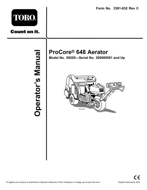
Form No. 3361-632 Rev C<br />
<strong>ProCore</strong> ® <strong>648</strong> <strong>Aerator</strong><br />
Model No. 09200—Serial No. 290000001 and Up<br />
To register your product or download an Operator's Manual or Parts Catalog at no charge, go to www.Toro.com.<br />
Original Instructions (EN)
Warning<br />
CALIFORNIA<br />
Proposition 65 Warning<br />
The engine exhaust from this product<br />
contains chemicals known to the State of<br />
California to cause cancer, birth defects,<br />
or other reproductive harm.<br />
This spark ignition system complies with Canadian<br />
ICES-002.<br />
Important: This engine is not equipped with a<br />
spark arrester muffler. It is a violation of California<br />
Public Resource Code Section 4442 to use or operate<br />
the engine on any forest-covered, brush-covered, or<br />
grass-covered land. Other states or federal areas<br />
may have similar laws.<br />
Introduction<br />
Read this information carefully to learn how to operate<br />
and maintain your product properly and to avoid injury<br />
and product damage. You are responsible for operating<br />
the product properly and safely.<br />
You may contact Toro directly at www.Toro.com for<br />
product and accessory information, help finding a<br />
dealer, or to register your product.<br />
Whenever you need service, genuine Toro parts, or<br />
additional information, contact an Authorized Service<br />
Dealer or Toro Customer Service and have the model<br />
and serial numbers of your product ready. Figure 1<br />
illustrates the location of the model and serial numbers<br />
on the product. Write the numbers in the space<br />
provided.<br />
Model No.<br />
Serial No.<br />
This manual identifies potential hazards and has<br />
safety messages identified by the safety alert symbol<br />
(Figure 2), which signals a hazard that may cause serious<br />
injury or death if you do not follow the recommended<br />
precautions.<br />
1. Safety alert symbol<br />
Figure 2<br />
This manual uses 2 other words to highlight information.<br />
Important calls attention to special mechanical<br />
information and Note emphasizes general information<br />
worthy of special attention.<br />
1<br />
Figure 1<br />
1. Location of the model and serial numbers<br />
© 2008—The Toro® Company<br />
8111 Lyndale Avenue South<br />
Bloomington, MN 55420 2<br />
Contact us at www.Toro.com.<br />
Printed in the USA.<br />
All Rights Reserved
Contents<br />
Introduction................................................................. 2<br />
Safety ........................................................................... 4<br />
Safe Operating Practices....................................... 4<br />
Sound Pressure Level ........................................... 5<br />
Sound Power Level............................................... 5<br />
Vibration Level..................................................... 5<br />
Safety and Instructional Decals............................. 6<br />
Setup.......................................................................... 10<br />
1 Installing the Rear Wheels ................................ 10<br />
2 Installing the Handle........................................ 11<br />
3 Activating and Charging the Battery.................. 11<br />
4 Securing the Rear Hood (CE Only)................... 13<br />
5 Securing the Belt Cover (CE Only) ................... 14<br />
6 Installing the Tine holders, Turf Guards, and<br />
Tines.............................................................. 15<br />
Product Overview ...................................................... 15<br />
Controls............................................................. 15<br />
Specifications ..................................................... 18<br />
Attachments/Accessories................................... 18<br />
Operation................................................................... 19<br />
Adding Fuel ....................................................... 19<br />
Checking the Engine Oil Level............................ 20<br />
Checking the Hydraulic Fluid.............................. 21<br />
Cleaning the Engine Screen ................................ 22<br />
Starting and Stopping the Engine........................ 23<br />
The Safety Interlock System................................ 23<br />
Installing the Service Latches .............................. 23<br />
Installing Tine Holders, Turf Guards, and<br />
Tines.............................................................. 24<br />
Replacing Tines .................................................. 25<br />
Setting the Coring Depth.................................... 25<br />
Setting Up Manual Ground Following................. 25<br />
Pushing/Pulling the <strong>Aerator</strong> by Hand ................. 26<br />
Resetting the System Control Circuit................... 27<br />
Moving the Machine when the Coring Head is<br />
Stranded in the Lowered Position.................... 27<br />
Transporting the <strong>Aerator</strong> .................................... 27<br />
Using the Line Marker ........................................ 28<br />
Adjusting the Weight Transfer............................. 28<br />
Adding Additional Weight .................................. 29<br />
<strong>Aerator</strong> Control Module (ACM).......................... 29<br />
Operating Tips ................................................... 30<br />
Maintenance............................................................... 33<br />
Recommended Maintenance Schedule(s) ................ 33<br />
Daily Maintenance Checklist............................... 34<br />
Premaintenance Procedures.................................... 35<br />
Jacking Instructions............................................ 35<br />
Lubrication............................................................. 36<br />
Checking the Coring Head Bearings .................... 36<br />
Engine Maintenance............................................... 36<br />
Servicing the Air Cleaner .................................... 36<br />
Changing the Engine Oil and Filter ..................... 37<br />
Servicing the Spark Plugs.................................... 38<br />
Fuel System Maintenance ....................................... 39<br />
Replacing the Fuel Filter ..................................... 39<br />
Draining the Fuel Tank....................................... 40<br />
Electrical System Maintenance................................ 40<br />
Servicing the Battery........................................... 40<br />
Fuses.................................................................. 41<br />
Drive System Maintenance ..................................... 42<br />
Checking the Tire Pressure ................................. 42<br />
Adjusting the Traction Drive for Neutral ............. 42<br />
Belt Maintenance.................................................... 43<br />
Adjusting the Pump Belt..................................... 43<br />
Inspecting the Belts ............................................ 43<br />
Controls System Maintenance................................. 44<br />
Resetting the Ground Following System.............. 44<br />
Hydraulic System Maintenance ............................... 44<br />
Checking the Hydraulic Lines ............................. 44<br />
Changing the Hydraulic Fluid and Filters............. 44<br />
Hydraulic System Test Ports ............................... 45<br />
<strong>Aerator</strong> Maintenance .............................................. 46<br />
Checking the Fastener Torque............................. 46<br />
Adjusting the Side Shields................................... 46<br />
Replacing the Turf Guards.................................. 46<br />
Adjusting Hole Spacing ...................................... 46<br />
Coring Head Timing........................................... 47<br />
Storage....................................................................... 48<br />
Troubleshooting......................................................... 49<br />
Schematics ................................................................. 51<br />
3
Safety<br />
Improper use or maintenance by the operator<br />
or owner can result in injury. To reduce the<br />
potential for injury, comply with these safety<br />
instructions and always pay attention to the safety<br />
alert symbol, which means Caution, Warning, or<br />
Danger—personal safety instruction. Failure to<br />
comply with the instruction may result in personal<br />
injury or death.<br />
Safe Operating Practices<br />
The following instructions are from the ANSI<br />
B71.4—2004 standard.<br />
Training<br />
• Read the Operator’s Manual and other training<br />
material. If the operator(s) or mechanic(s) can not<br />
read English it is the owner’s responsibility to explain<br />
this material to them.<br />
• Become familiar with the safe operation of the<br />
equipment, operator controls, and safety signs.<br />
• All operators and mechanics should be trained. The<br />
owner is responsible for training the users.<br />
• Never let children or untrained people operate or<br />
service the equipment. Local regulations may restrict<br />
the age of the operator.<br />
• The owner/user can prevent and is responsible for<br />
accidents or injuries occurring to himself or herself,<br />
other people or property.<br />
Preparation<br />
• Evaluate the terrain to determine what accessories<br />
and attachments are needed to properly and<br />
safely perform the job. Only use accessories and<br />
attachments approved by the manufacturer.<br />
• Wear appropriate clothing including hard hat, safety<br />
glasses, and hearing protection. Long hair, loose<br />
clothing, or jewelry may get tangled in moving parts.<br />
• Inspect the area where the equipment is to be used<br />
and remove all objects such as rocks, toys, and wire<br />
which can be contacted by the aerator.<br />
• Use extra care when handling gasoline and other<br />
fuels. They are flammable and vapors are explosive.<br />
– Use only an approved container.<br />
– Never remove the gas cap or add fuel with the<br />
engine running.<br />
– Allow the engine to cool before refueling.<br />
– Do not smoke.<br />
– Never refuel or drain the aerator indoors.<br />
• Check that the operator presence controls, safety<br />
switches, and shields are attached and functioning<br />
properly. Do not operate unless they are functioning<br />
properly.<br />
Operation<br />
• Never run an engine in an enclosed area.<br />
• Only operate in good light, keeping away from holes<br />
and hidden hazards.<br />
• Be sure all drives are in neutral and parking brake is<br />
engaged before starting engine. Start the engine only<br />
from the operator’s position.<br />
• Never operate without the shields, covers, or other<br />
guards securely in place. Be sure all interlocks are<br />
functioning properly.<br />
• Do not change the engine governor setting or<br />
overspeed the engine.<br />
• Stop on level ground, raise the coring head,<br />
disengage drives, engage the parking brake, and shut<br />
off the engine before leaving the operator’s position<br />
for any reason.<br />
• Stop the equipment and inspect the tines after<br />
striking an object or if an abnormal vibration occurs.<br />
Make necessary repairs before resuming operation.<br />
• Keep hands and feet away from the tine area.<br />
• Never carry passengers and keep pets and bystanders<br />
away.<br />
• Be alert, slow down, and use caution when making<br />
turns. Look behind and to the side before changing<br />
directions.<br />
• Slow down and use caution when crossing roads<br />
and sidewalks.<br />
• Do not operate the aerator under the influence of<br />
alcohol or drugs.<br />
• Use extreme care when loading or unloading the<br />
aerator into a trailer or truck.<br />
• Use care when approaching blind corners, shrubs,<br />
trees, or other objects that may obscure vision.<br />
• Always be aware of obstacles that may be in the<br />
area of operation. Plan your aeration path to avoid<br />
contact with any obstacle by you or the machine.<br />
Slope Operation<br />
• Do not operate near drop-offs, ditches, steep banks,<br />
or water. Wheels dropping over edges can cause<br />
rollovers, which may result in serious injury or death.<br />
4
• Do not operate on slopes when grass is wet. Slippery<br />
conditions reduce traction and could cause sliding<br />
and loss of control.<br />
• Do not make sudden turns or rapid speed changes.<br />
• Reduce speed and use extreme caution on slopes.<br />
• Remove or mark obstacles such as rocks, tree limbs,<br />
etc. from the operating area. Tall grass can hide<br />
obstacles.<br />
• Watch for ditches, holes, rocks, dips, and rises that<br />
change the operating angle, as rough terrain could<br />
overturn the aerator.<br />
• Always avoid sudden starting or stopping on a slope.<br />
If tires lose traction, disengage the tines and proceed<br />
slowly off the slope.<br />
• Follow the recommendations for wheel weights or<br />
counterweights to improve stability.<br />
Maintenance and Storage<br />
• Wait for all movement to stop before adjusting,<br />
cleaning, or repairing. Disengage the tines, raise the<br />
coring head, set the parking brake, stop the engine,<br />
and remove the key.<br />
• Clean grass and debris from the tines, drives,<br />
mufflers, and engine to help prevent fires. Clean up<br />
oil or fuel spillage.<br />
• Let the engine cool before storing and do not store<br />
near flame.<br />
• Shut off the fuel while storing or transporting on<br />
trailers. Do not store fuel near flames or drain<br />
indoors.<br />
• Park the aerator on level, hard ground. Never allow<br />
untrained personnel to service it.<br />
• Use jack stands or safety latches to support<br />
components when required.<br />
• Carefully release pressure from components with<br />
stored energy.<br />
• Disconnect the battery or remove the spark plug<br />
wires before making any repairs. Disconnect<br />
the negative terminal first and the positive last.<br />
Reconnect the positive first and the negative last.<br />
• Keep hands and feet away from moving parts. If<br />
possible, do not make adjustments with the engine<br />
running.<br />
• Charge batteries in an open well ventilated area, away<br />
from spark and flames. Unplug the charger before<br />
connecting or disconnecting it from the battery.<br />
Wear protective clothing and use insulated tools.<br />
• Keep all parts in good working condition and all<br />
hardware tightened. Replace all worn or damaged<br />
decals.<br />
• Use only Toro-approved attachments. The<br />
warranty may be voided if the machine is used with<br />
unapproved attachments.<br />
Sound Pressure Level<br />
This machine has an equivalent continuous A-weighted<br />
sound pressure at the operator ear of: 84 dB(A), based<br />
on measurements of identical machines per ISO 11201.<br />
Sound Power Level<br />
This machine has a guaranteed sound power level of:<br />
105 dBA/1 pW, based on measurements of identical<br />
machines per ISO 3744.<br />
Vibration Level<br />
This unit does not exceed a vibration level of 2.5 m/s 2 at<br />
the hands based on measurements of identical machines<br />
per EN 1033 and EN 836.<br />
This unit does not exceed a vibration level of 0.5 m/s 2<br />
at the posterior based on measurements of identical<br />
machines per EN 1032 and EN 836.<br />
5
Safety and Instructional Decals<br />
Safety decals and instructions are easily visible to the operator and are located near any area of<br />
potential danger. Replace any decal that is damaged or lost.<br />
93–6696<br />
1. Stored energy hazard—read the Operator’s Manual.<br />
93-9084<br />
1. Lift point 2. Tie-down point<br />
106-8835<br />
1. On/off 7. Head low<br />
2. Output 8. Head high<br />
3. Solenoid valve lower 9. Transport (1)<br />
4. Solenoid valve raise 10. Aerate (4)<br />
5. Solenoid valve quick 11. Ground following<br />
6. Input 12. OK to lower<br />
93-9363<br />
1. Parking brake 3. Unlocked<br />
2. Locked<br />
1. Read the Operator’s<br />
Manual.<br />
106-8853<br />
2. Coring depth<br />
6
110-4664<br />
1. Read the Operator’s 3. Bolt size<br />
Manual.<br />
2. Wrench size 4. Torque<br />
106-8856<br />
1. Read the Operator’s Manual.<br />
Battery Symbols<br />
Some or all of these symbols are on your battery<br />
1. Explosion hazard 6. Keep bystanders a safe<br />
distance from the battery.<br />
2. No fire, open flame, or<br />
smoking.<br />
7. Wear eye protection;<br />
explosive gases can<br />
cause blindness and other<br />
injuries<br />
3. Caustic liquid/chemical<br />
burn hazard<br />
8. Battery acid can cause<br />
blindness or severe burns.<br />
4. Wear eye protection 9. Flush eyes immediately<br />
with water and get medical<br />
help fast.<br />
5. Read the Operator’s<br />
Manual.<br />
10. Contains lead; do not<br />
discard.<br />
1. Entanglement hazard,<br />
belt—stay away from<br />
moving parts.<br />
107-7547<br />
2. Warning—Do not touch<br />
the hot surfaces<br />
107-7555<br />
7
106-8854<br />
1. Read the Operator’s Manual. 4. Engine—start 7. To start the engine, turn the ignition<br />
key and unlock the parking brake; read<br />
the Operator’s Manual.<br />
2. Engine—stop 5. Read the Operator’s Manual; move the<br />
switch up to turn ground following on;<br />
move the switch down and install the<br />
spacers to turn ground following off.<br />
3. Engine—run 6. Read the Operator’s Manual; press the<br />
switch to test the safety system.<br />
8. To stop the engine, press the switch to<br />
disengage the PTO, lock the parking<br />
brake, and turn the ignition key to the<br />
Stop position and remove it; read the<br />
Operator’s Manual.<br />
9. Transport or hole spacing selection<br />
8
115-4716<br />
1. Warning—do not operate this machine unless you are trained. 7. Warning—stop the engine and read the instructions before<br />
servicing or performing maintenance.<br />
2. Crushing hazard—Walk in a forward direction while operating<br />
the machine, do not walk and face backwards when operating<br />
the machine, always look down and behind you when walking<br />
backwards while operating the machine.<br />
8. Entanglement hazard, belt; crushing hazard of hand or<br />
foot—stay away from moving parts, keep all guards and<br />
shields in place; keep bystanders a safe distance from the<br />
machine.<br />
3. Move the lever up to drive in reverse. 9. Warning—stop the engine before fueling.<br />
4. Move the lever down to drive forward. 10. Entanglement hazard, shaft—do not carry passengers.<br />
5. Disengage the PTO and raise the head. 11. Tipping hazard—do not turn sharply while traveling fast, drive<br />
slowly when turning, and do not drive the machine on a slope<br />
greater than 15 degrees.<br />
6. Engage the PTO and lower the head.<br />
107-7534<br />
1. Warning—read the Operator’s Manual. 3. Entanglement hazard, belt—stay away<br />
from moving parts.<br />
2. Warning—remove the ignition key and<br />
read the instructions before servicing<br />
or performing maintenance.<br />
4. Crushing hazard of hand or foot—keep<br />
bystanders a safe distance from the<br />
machine.<br />
5. Crushing hazard of hand and<br />
body—engage the service latch<br />
when the coring head is raised; read<br />
the instructions before servicing or<br />
performing maintenance.<br />
6. Read the instructions before servicing<br />
or performing maintenance—torque<br />
the tine bolts to 41 N-m (30 ft-lb).<br />
9
Setup<br />
Loose Parts<br />
Use the chart below to verify that all parts have been shipped.<br />
Procedure Description Qty. Use<br />
1<br />
Wheel assembly Install the rear wheels.<br />
2<br />
Locknut (1/2 inch) 3<br />
Cable guide 1<br />
Bolt (5/16 x 1/2 inch) 2<br />
Install the handle.<br />
3<br />
Bolt (1/4 x 1 inch) 2<br />
Flange nut (5/16 inch) 2<br />
Activate and charge the battery.<br />
Hood plate 1<br />
4<br />
Pop rivet 3<br />
Nut (#10) 1<br />
Bolt (#10 x 2 inch) 1<br />
Securing the rear hood (CE only).<br />
Locknut (#10) 1<br />
5<br />
Bolt (1/4 x 1 inch) 1<br />
Locknut (1/4 inch) 1<br />
Secure the belt cover (CE only).<br />
6<br />
No parts required –<br />
Install the tine holders, turf guards, and<br />
tines.<br />
Media and Additional Parts<br />
Description Qty. Use<br />
Ignition key 2 Start the machine<br />
Turf guard clamp 4<br />
Flange nut 12<br />
Operator’s Manual 1<br />
Engine Operator’s Manual 1<br />
Install the turf guards.<br />
Read before operating the machine.<br />
Operator training material 1 View before operating the machine.<br />
Parts Catalog 1 View and order parts.<br />
Certificate of compliance 1 CE certification<br />
Pre-delivery checklist 1<br />
Note: Determine the left and right sides of the machine<br />
from the normal operating position.<br />
Note: To raise the coring head after uncrating the<br />
machine, start the engine and press the Reset button.<br />
Refer to the Operation section of this manual for more<br />
information.<br />
Ensure that all setup procedures have been completed<br />
before delivery.<br />
10
1<br />
Installing the Rear Wheels<br />
Parts needed for this procedure:<br />
1<br />
4<br />
Procedure<br />
Wheel assembly<br />
1. Remove the 8 lug nuts securing the rear of the<br />
aerator to the packaging.<br />
2. Mount a wheel assembly onto each rear wheel hub<br />
(Figure 3).<br />
1<br />
2<br />
Figure 4<br />
1. Handle 3. Locknut<br />
2. Fork 4. Cable guide<br />
G00XXXX<br />
3. Secure handle studs to fork with 3 locknuts (1/2<br />
inch) (Figure 4)<br />
4. Insert the cable guide around the cables.<br />
5. Mount the cable guide to the top of the fork with 2<br />
bolts (5/16 x 1/2 inch) (Figure 4).<br />
3<br />
Figure 3<br />
1. Wheel assembly 2. Lug nut<br />
2<br />
G010018<br />
3<br />
Activating and Charging the<br />
Battery<br />
3. Install the lug nuts (Figure 3) and tighten them to 45<br />
to 55 ft-lb (61 to 75 N-m).<br />
4. Deflate all four tires to 12 psi (83 kPa).<br />
2<br />
Installing the Handle<br />
Parts needed for this procedure:<br />
3 Locknut (1/2 inch)<br />
1 Cable guide<br />
2 Bolt (5/16 x 1/2 inch)<br />
Procedure<br />
1. Carefully rotate the handle to the front of the<br />
machine. Use caution not to damage the cables.<br />
2. Insert the handle mounting studs into the holes in<br />
the fork (Figure 4).<br />
Parts needed for this procedure:<br />
2 Bolt (1/4 x 1 inch)<br />
2 Flange nut (5/16 inch)<br />
Procedure<br />
Warning<br />
CALIFORNIA<br />
Proposition 65 Warning<br />
Battery posts, terminals, and related<br />
accessories contain lead and lead compounds,<br />
chemicals known to the State of California<br />
to cause cancer and reproductive harm.<br />
Wash hands after handling.<br />
1. Unlatch and open the battery compartment cover.<br />
2. Remove the battery from the battery compartment<br />
(Figure 5).<br />
11
Charging the battery produces gasses that can<br />
explode.<br />
Never smoke near the battery and keep sparks<br />
and flames away from it.<br />
1. Battery compartment<br />
Figure 5<br />
3. Clean the top of the battery and remove the vent<br />
caps.<br />
4. Carefully fill each cell with electrolyte until the plates<br />
are covered with about 1/4 inch (6 mm) of fluid.<br />
Use only electrolyte (1.265 Specific Gravity) to fill<br />
the battery initially.<br />
Important: Do not add electrolyte while the<br />
battery is in the machine. You could spill it,<br />
causing corrosion.<br />
Battery electrolyte contains sulfuric acid which<br />
is a deadly poison and causes severe burns.<br />
• Do not drink electrolyte and avoid contact<br />
with skin, eyes, or clothing. Wear safety<br />
glasses to shield your eyes and rubber gloves<br />
to protect your hands.<br />
• Fill the battery where clean water is always<br />
available for flushing the skin.<br />
1<br />
7. When the battery is charged, disconnect the charger<br />
from the electrical outlet and battery posts.<br />
Note: After the battery has been activated, add<br />
only distilled water to replace normal loss, although<br />
maintenance-free batteries should not require water<br />
under normal operating conditions.<br />
8. Insert the battery into the tray in the battery<br />
compartment (Figure 6) Position the battery so the<br />
terminals are to the outside.<br />
Battery terminals or metal tools could short<br />
against metal machine components causing<br />
sparks. Sparks can cause the battery gasses to<br />
explode, resulting in personal injury.<br />
• When removing or installing the battery, do<br />
not allow the battery terminals to touch any<br />
metal parts of the machine.<br />
• Do not allow metal tools to short between<br />
the battery terminals and metal parts of the<br />
machine.<br />
9. Secure the battery to the compartment base with a<br />
battery rod, 2 hold down rods, 2 flat washers, and 2<br />
wing nuts (Figure 6).<br />
5. Allow approximately 20 to 30 minutes to allow all<br />
trapped gas to escape from the plates. Refill as<br />
necessary to bring the electrolyte to within about 1/4<br />
inch (6 mm) of the bottom of the fill well.<br />
6. Connect a 3 to 4 amp battery charger to the battery<br />
posts. Charge the battery at a rate of 3 to 4 amps<br />
until the specific gravity is 1.250 or higher and the<br />
temperature is at least 60 degrees F (16 degrees C)<br />
with all cells gassing freely.<br />
12
4<br />
2<br />
5<br />
1<br />
Incorrect battery cable routing could damage<br />
the machine and cables causing sparks. Sparks<br />
can cause the battery gasses to explode,<br />
resulting in personal injury.<br />
• Always disconnect the negative (black)<br />
battery cable before disconnecting the<br />
positive (red) cable.<br />
• Always connect the positive (red) battery<br />
cable before connecting the negative (black)<br />
cable.<br />
11. Close and latch the battery compartment cover.<br />
3<br />
Figure 6<br />
G010021<br />
1. Battery tray 4. Positive terminal (+)<br />
2. Battery hold down 5. Negative terminal (–)<br />
3. Hold down rod<br />
10. First, secure the positive cable (red) to the positive<br />
(+) battery terminal with a carriage bolt and nut<br />
(Figure 6), then the negative cable (black) to the<br />
negative (–) terminal of the battery with a carriage<br />
bolt and nut (Figure 6). Slide the rubber boot over<br />
the positive terminal to prevent a possible short<br />
from occurring.<br />
Important: Make sure there is clearance<br />
between the battery cables and the speed<br />
selector lever. Verify that the speed selector lever<br />
does not come within 1 inch (2.5 cm) of either<br />
battery cable when it is moved through its entire<br />
range of motion. Do not wire tie or tape the<br />
negative and positive battery cables together.<br />
4<br />
Securing the Rear Hood (CE<br />
Only)<br />
Parts needed for this procedure:<br />
1 Hood plate<br />
3 Pop rivet<br />
1 Nut (#10)<br />
1 Bolt (#10 x 2 inch)<br />
1 Locknut (#10)<br />
Procedure<br />
If you are setting up this machine for use in the<br />
European Union (CE), secure the rear hood as follows<br />
to comply with CE regulations.<br />
1. Secure the hood plate to the rear hood with 3 pop<br />
rivets (Figure 7 and Figure 8).<br />
13
1<br />
5<br />
Securing the Belt Cover (CE<br />
Only)<br />
Parts needed for this procedure:<br />
1 Bolt (1/4 x 1 inch)<br />
1 Locknut (1/4 inch)<br />
1. Rear hood<br />
Figure 7<br />
Procedure<br />
If you are setting up this machine for use in the<br />
European Union (CE), secure the belt cover as follows<br />
to comply with CE regulations.<br />
Insert a Bolt (1/4 x 1 inch) through the belt cover latch<br />
lever and secure with a locknut (1/4 inch) (Figure 9 and<br />
Figure 10)<br />
2<br />
1<br />
2<br />
3<br />
Figure 8<br />
1. Hood plate 3. Bolt and nuts<br />
2. Pop rivet<br />
1<br />
2. Thread a nut (#10) onto a bolt (#10 x 2 inch).<br />
3. Insert the bolt through the hood plate (Figure 8).<br />
4. Secure the bolt to the hood plate with a locknut<br />
(#10) (Figure 8).<br />
Figure 9<br />
1. Belt cover 2. Latch lever<br />
14
Product Overview<br />
2<br />
1<br />
Figure 10<br />
1. Latch lever 2. Bolt and nut<br />
6<br />
Installing the Tine holders,<br />
Turf Guards, and Tines<br />
Figure 11<br />
1. Operating direction 3. Left side<br />
2. Right side<br />
Controls<br />
Become familiar with all the controls before you start<br />
the engine and operate the aerator.<br />
No Parts Required<br />
Procedure<br />
A wide selection of tine holders, turf guards, and tines<br />
are available for the aerator. Install the setup appropriate<br />
for your application as described in Installing the Tine<br />
holders, Turf Guards, and Tines in Operation.<br />
Figure 12<br />
1. Traction lever 3. Raise, lower/engage<br />
switch<br />
2. Parking brake 4. Oil pressure warning light<br />
Traction Lever<br />
To move forward, move the traction lever forward.<br />
To move rearward, move the traction lever rearward<br />
(Figure 12).<br />
The farther you move the traction lever, the faster the<br />
aerator will move.<br />
To stop, release the traction lever.<br />
15
Parking Brake<br />
To engage the parking brake, move the lever toward the<br />
engine. To disengage the parking brake, move the lever<br />
forward (Figure 12).<br />
Always set the parking brake when you stop the aerator<br />
or leave it unattended.<br />
Jog the traction lever forward and reverse to release the<br />
parking brake.<br />
Oil Pressure Warning Light<br />
The oil pressure warning light (Figure 12) glows when<br />
the oil pressure in the engine drops below a safe level.<br />
If low oil pressure ever occurs, stop the engine and<br />
determine the cause. Repair the damage before starting<br />
the engine again.<br />
Raise, Lower/Engage Switch<br />
Raise—Press the top of the switch (Figure 12) to raise<br />
the coring head and disengage the coring head. The<br />
engine must be running to generate lift pressure. If<br />
the coring head is below the transport height, refer to<br />
System Control Circuit Reset.<br />
Lower/Engage—Press the bottom of the switch<br />
(Figure 12) to lower and engage the coring head. The<br />
traction lever must be in the forward position to activate<br />
the switch.<br />
Keep hands and feet away from the coring head.<br />
Make sure the coring head area is clear of any<br />
obstructions before lowering it.<br />
To lower the coring head without engaging it, turn the<br />
ignition key to the Run position (without the engine<br />
running), move the traction lever to the forward<br />
position, and press the bottom of the switch.<br />
Ignition Switch<br />
The ignition switch (Figure 13), which is used to start<br />
and stop the engine, has three positions: Off, Run, and<br />
Start. Rotate key clockwise to the Start position to<br />
engage starter motor. When engine starts, release key<br />
and it will move automatically to the On position. To<br />
shut the engine off, rotate the key counterclockwise to<br />
the Off position.<br />
2<br />
1<br />
3<br />
Figure 13<br />
1. Ignition 5. Hour meter/tachometer<br />
2. <strong>Aerator</strong> spacing lever 6. Manual ground follow<br />
3. Throttle 7. System reset<br />
4. Choke<br />
<strong>Aerator</strong> Spacing Lever<br />
Move aerator spacing lever (Figure 13) to desired hole<br />
spacing or to T for transport.<br />
Throttle Control<br />
The throttle (Figure 13) is used to operate engine at<br />
various speeds. Moving throttle forward increases<br />
engine speed (Fast position); backward decreases engine<br />
speed (Slow position). The throttle regulates the speed<br />
of the coring head and controls the ground speed of<br />
the machine.<br />
Hour Meter/Tachometer<br />
When the engine is off, the hour meter/tachometer<br />
(Figure 13) displays the number of hours of operation<br />
that have been logged on the machine. When the<br />
engine is running, it displays the speed of the engine in<br />
revolutions per minute (RPM).<br />
After the first 50 hours of operation and then after every<br />
100 hours (e.g. 150, 250, 350, etc.) the screen displays<br />
“CHG OIL” to remind you to change the engine oil.<br />
After every 100 hours (e.g. 100, 200, 300, etc.), the<br />
screen displays “SVC” to remind you to perform the<br />
other maintenance procedures based on a 100, 200, or<br />
500 hour schedule. These reminders come on starting<br />
three hours prior to the service interval time and flash at<br />
regular intervals for six hours.<br />
4<br />
5<br />
6<br />
7<br />
16
Choke<br />
To start a cold engine, close the carburetor choke by<br />
moving choke control (Figure 13) fully forward. After<br />
the engine starts, regulate the choke to keep the engine<br />
running smoothly. As soon as possible, open the choke<br />
by pulling it backward.<br />
Manual Ground Follow Selector Switch<br />
Rotate the switch to the down position to turn off the<br />
TrueCore feature (Figure 13) Remove the bolt to access<br />
the manual ground switch.<br />
System Reset<br />
Press the system reset switch (Figure 13) to raise the<br />
coring head if the system becomes disabled (e.g., engine<br />
out of fuel, etc.)<br />
Aeration Depth Lever<br />
Move the lever to the desired depth of aeration<br />
(Figure 14)<br />
1<br />
2<br />
1. Aeration depth lever<br />
2. Depth decal<br />
Figure 14<br />
17
Specifications<br />
Note: Specifications and design are subject to change without notice.<br />
Width<br />
Wheel base<br />
Track width<br />
Coring width<br />
Length<br />
Height, raised<br />
Height, Lowered<br />
Height, handle<br />
Weight without fuel<br />
Ground clearance<br />
Forward speed<br />
Reverse speed<br />
50.12 inches (127.3 cm)<br />
44.5 inches (113 cm)<br />
38.3 inches (97.3 cm)<br />
48 inches (122 cm)<br />
104.5 inches ((265.4 cm)<br />
44 inches (112 cm)<br />
44 inches (112 cm)<br />
41 inches (104 cm)<br />
1590 lb (721 kg)<br />
4.75 inches (12.1 cm)<br />
0–5 mph (0–8 kph)<br />
0–8 mph (0–13 kph)<br />
Attachments/Accessories<br />
A selection of Toro approved attachments and accessories are available for use with the machine to enhance and<br />
expand its capabilities. Contact your Authorized Service Dealer or Distributor or go to www.Toro.com for a list of<br />
all approved attachments and accessories.<br />
Refer to the following table for the tine head, tine holder, and tine configurations:<br />
Tine Head Tine Head Spacing Shank Size Tine Head Model<br />
2x5 Mini Tine Head 1.6 inch (41 mm) 3/8 inch 09736<br />
1x6 Mini Tine Head 1.25 inch (32 mm) 3/8 inch 09737<br />
3 Tine Head 2.6 inch (66 mm) 7/8 inch 09797<br />
3 Tine Head 2.6 inch (66 mm) 3/4 inch 09794<br />
4 Tine Head 2 inch (51 mm) 3/4 inch 09796<br />
5 Needle Tine Head 1.6 inch (41 mm) — 09793<br />
Turf Holders<br />
Required (qty)<br />
110–4365 (2)<br />
110–4366 (1)<br />
110-4369 (2)<br />
110-4370 (1)<br />
110–4357 (1)<br />
110–4358 (1)<br />
110–4357 (1)<br />
110–4358 (1)<br />
110–4361 (1)<br />
110–4362 (1)<br />
110–4365 (2)<br />
110–4366 (1)<br />
Tines Required<br />
60<br />
36<br />
18<br />
18<br />
24<br />
30<br />
18
Operation<br />
Note: Determine the left and right sides of the<br />
machine from the normal operating position.<br />
If you leave the key in the ignition switch,<br />
someone could accidently start the engine and<br />
seriously injure you or other bystanders.<br />
Lower the coring head to the ground, set the<br />
parking brake, and remove the key from the<br />
ignition switch before servicing or making<br />
adjustments to the machine.<br />
Adding Fuel<br />
Use unleaded gasoline (87 pump octane minimum).<br />
Leaded, regular gasoline may be used if unleaded is not<br />
available.<br />
In certain conditions, gasoline is extremely<br />
flammable and highly explosive. A fire or<br />
explosion from gasoline can burn you and<br />
others and can damage property.<br />
• Fill the fuel tank outdoors, in an open area,<br />
when the engine is cold. Wipe up any<br />
gasoline that spills.<br />
• Never fill the fuel tank inside an enclosed<br />
trailer.<br />
• Do not fill the fuel tank completely full. Add<br />
gasoline to the fuel tank until the level is 1/4<br />
to 1/2 inch (6 to 13 mm) below the bottom of<br />
the filler neck. This empty space in the tank<br />
allows gasoline to expand.<br />
• Never smoke when handling gasoline, and<br />
stay away from an open flame or where<br />
gasoline fumes may be ignited by a spark.<br />
• Store gasoline in an approved container and<br />
keep it out of the reach of children. Never<br />
buy more than a 30-day supply of gasoline.<br />
• Do not operate without entire exhaust<br />
system in place and in proper working<br />
condition.<br />
In certain conditions during fueling, static<br />
electricity can be released causing a spark<br />
which can ignite the gasoline vapors. A fire<br />
or explosion from gasoline can burn you and<br />
others and can damage property.<br />
• Always place gasoline containers on the<br />
ground away from your vehicle before filling.<br />
• Do not fill gasoline containers inside a<br />
vehicle or on a truck or trailer bed because<br />
interior carpets or plastic truck bed liners<br />
may insulate the container and slow the loss<br />
of any static charge.<br />
• When practical, remove gas-powered<br />
equipment from the truck or trailer and<br />
refuel the equipment with its wheels on the<br />
ground.<br />
• If this is not possible, then refuel such<br />
equipment on a truck or trailer from a<br />
portable container, rather than from a<br />
gasoline dispenser nozzle.<br />
• If a gasoline dispenser nozzle must be used,<br />
keep the nozzle in contact with the rim of<br />
the fuel tank or container opening at all<br />
times until fueling is complete.<br />
Important: Do not use methanol, gasoline<br />
containing methanol, or gasohol containing more<br />
than 10% ethanol because the fuel system could be<br />
damaged. Do not mix oil with gasoline.<br />
Gasoline is harmful or fatal if swallowed.<br />
Long–term exposure to vapors can cause<br />
serious injury and illness.<br />
• Avoid prolonged breathing of vapors.<br />
• Keep face away from nozzle and gas tank or<br />
conditioner opening.<br />
• Keep gas away from eyes and skin.<br />
Using Stabilizer/Conditioner<br />
Use a fuel stabilizer/conditioner in the traction unit to<br />
provide the following benefits:<br />
• Keeps gasoline fresh during storage of 90 days or<br />
less. For longer storage it is recommended that the<br />
fuel tank be drained.<br />
19
• Cleans the engine while it runs<br />
• Eliminates gum-like varnish buildup in the fuel<br />
system, which causes hard starting<br />
Important: Do not use fuel additives containing<br />
methanol or ethanol.<br />
Add the correct amount of gas stabilizer/conditioner<br />
to the gas.<br />
Note: A fuel stabilizer/conditioner is most effective<br />
when mixed with fresh gasoline. To minimize the<br />
chance of varnish deposits in the fuel system, use fuel<br />
stabilizer at all times.<br />
Filling the Fuel Tank<br />
The fuel tank capacity is approximately 7 gal (26.5 l)<br />
1. Stop the engine, remove the key, and wait for all<br />
moving parts to stop before leaving the operating<br />
position.<br />
2. Clean around the fuel tank cap and remove it<br />
(Figure 15).<br />
1<br />
Checking the Engine Oil Level<br />
Service Interval: Before each use or daily (Check the<br />
oil when the engine is cold.)<br />
The engine is shipped with oil in the crankcase;<br />
however, the oil level must be checked before and after<br />
the engine is first started.<br />
Crankcase capacity is approximately 3.5 qt. (3.3 l) with<br />
the filter.<br />
Use high-quality engine oil as described in Servicing<br />
the Engine Oil.<br />
Note: The best time to check the engine oil is when<br />
the engine is cool before it has been started for the<br />
day. If it has already been run, allow the oil to drain<br />
back down to the sump for at least 10 minutes before<br />
checking. If the oil level is at or below the “add” mark<br />
on the dipstick, add oil to bring the oil level to the “full”<br />
mark. DO NOT OVERFILL. If the oil level is between<br />
the “full” and “add” marks, no oil addition is required.<br />
1. Park the machine on a level surface, stop the engine,<br />
remove the key, and wait for all moving parts to<br />
stop before leaving the operating position.<br />
2. Clean around the oil dipstick (Figure 16) so dirt<br />
cannot fall into the filler hole and damage the<br />
engine.<br />
1. Fuel tank cap<br />
Figure 15<br />
3. Add unleaded gasoline to the fuel tank, until the<br />
level is 1/4 to 1/2 inch (6 mm to 13 mm) below the<br />
bottom of the filler neck.<br />
Important: This space in the tank allows<br />
gasoline to expand. Do not fill the fuel tank<br />
completely full.<br />
4. Install the fuel tank cap securely.<br />
5. Wipe up any gasoline that may have spilled.<br />
Figure 16<br />
1. Dipstick 3. Metal end of the dipstick<br />
2. Filler tube<br />
3. Remove the dipstick, wipe it clean, and install until<br />
it is fully seated (Figure 16).<br />
4. Remove the dipstick and check the oil level on the<br />
dipstick.<br />
The oil level should be up to the Full mark on the<br />
metal end of the dipstick (Figure 16).<br />
5. If the oil level is below the Full mark, remove the<br />
filler tube cap (Figure 16) and add oil until the level<br />
reaches the Full mark on the dipstick. Do not<br />
overfill.<br />
20
Important: Do not overfill the crankcase with<br />
oil because this may cause engine damage. Do<br />
not run the engine with oil below the low mark<br />
because the engine may be damaged as a result.<br />
6. Install the filler tube cap and dipstick.<br />
Checking the Hydraulic Fluid<br />
Service Interval: Before each use or daily<br />
The hydraulic reservoir is filled at the factory with<br />
approximately 1.75 US gallons (6.6 l) of high quality<br />
hydraulic fluid. Check the level of the hydraulic<br />
fluid before the engine is first started and daily<br />
thereafter. The recommended replacement fluid is as<br />
follows:<br />
Toro Premium All Season Hydraulic Fluid (Available in<br />
5 gallon pails or 55 gallon drums. See the parts catalog or<br />
your Toro distributor for part numbers.)<br />
Alternate fluids: If the Toro fluid is not available, other<br />
fluids may be used provided they meet all the following<br />
material properties and industry specifications. Toro<br />
does not recommend the use of synthetic fluid. Consult<br />
with your lubricant distributor to identify a satisfactory<br />
product.<br />
Note: Toro will not assume responsibility for damage<br />
caused by improper substitutions, so use only products<br />
from reputable manufacturers who will stand behind<br />
their recommendation.<br />
High Viscosity Index/Low Pour Point Anti-wear Hydraulic<br />
Fluid, ISO VG 46<br />
Material Properties:<br />
Viscosity, ASTM D445 cSt @ 40°C 55 to 62<br />
cSt @ 100°C 9.1 to 9.8<br />
Viscosity Index ASTM 140 to 152<br />
D2270<br />
Pour Point, ASTM D97 -35°F to -46°F<br />
Industry Specifications:<br />
API GL–4, AGCO Powerfluid 821 XL, Ford New Holland<br />
FNHA–2–C–201.00, Kubota UDT, John Deere J20C,<br />
Vickers 35VQ25 and Volvo WB–101/BM.<br />
Note: Many hydraulic fluids are almost colorless,<br />
making it difficult to spot leaks. A red dye additive<br />
for the hydraulic system oil is available in 2/3 oz. (20<br />
ml) bottles. One bottle is sufficient for 4-6 gal (15-22<br />
1) of hydraulic oil. Order part no. 44-2500 from your<br />
authorized Toro distributor.<br />
Important: For this machine, the Universal Tractor<br />
Hydraulic Fluids (UTHF) are recommended for<br />
use at typical ambient temperatures of 32 degrees<br />
F (0 degrees C) to 95 degrees F (35 degrees C).<br />
The Universal Tractor Fluids (UTHF) offer similar<br />
performance for those who prefer them, with<br />
perhaps some slight loss of efficiency at high<br />
ambient temperatures compared to the Type 46/68<br />
fluids.<br />
Important: For operating conditions where<br />
sustained ambient temperatures are 95 degrees F<br />
(35 degrees C) or higher Toro highly recommends<br />
the use of Mobil 1 15W–50 synthetic oil.<br />
21
Note: When changing from one type of hydraulic fluid<br />
to another, be certain to remove all the old fluid from<br />
the system, as some fluids are incompatible with others.<br />
Biodegradable Hydraulic Fluid - Mobil 224H<br />
ISO VG 32/46 anti-wear hydraulic fluid<br />
Mobil EAL Envirosyn H, ISO Grade 68<br />
Note: This synthetic biodegradable hydraulic fluid is<br />
not compatible with the UTHF fluids.<br />
Note: When changing from standard fluid to the<br />
biodegradable type, be certain to follow approved<br />
flushing procedures as published by Mobil. Contact<br />
your local Toro Distributor for details.<br />
1. Position the machine on a level surface, stop the<br />
engine, remove the key, and wait for all moving<br />
parts to stop before leaving the operating position.<br />
2. Unlatch and remove the belt cover (Figure 17).<br />
2<br />
1<br />
1. Hydraulic tank cap<br />
Figure 18<br />
4. Remove dipstick from filler neck and wipe it with<br />
a clean rag. Insert dipstick into filler neck; then<br />
remove it and check level of fluid. Fluid level should<br />
be up to mark on dipstick (Figure 19).<br />
1<br />
1<br />
2<br />
Figure 19<br />
G010029<br />
1. Dipstick 2. Full mark<br />
Figure 17<br />
1. Belt cover 2. Cover latch<br />
3. Clean area around filler neck and cap of hydraulic<br />
tank (Figure 18). Remove cap from filler neck.<br />
5. If level is low, add appropriate fluid to raise level<br />
to full mark.<br />
6. Install dipstick and cap onto filler neck.<br />
Cleaning the Engine Screen<br />
Service Interval: Before each use or daily (Clean<br />
more frequently in dirty operating<br />
conditions.)<br />
Before each use, check and clean the engine screen.<br />
Remove any buildup of grass, dirt or other debris from<br />
the engine air intake screen.<br />
22
Starting and Stopping the<br />
Engine<br />
Starting the Engine<br />
1. Release the traction lever (bail) and set the parking<br />
brake.<br />
2. Move the choke control to the On position before<br />
starting a cold engine.<br />
Note: A warm or hot engine may not require<br />
choking. After the engine starts, move the choke<br />
control to the Run position.<br />
3. Move the throttle control to the Fast position<br />
before starting a cold engine.<br />
4. Turn the ignition key to start. When the engines<br />
starts, release the key.<br />
Important: Do not engage the starter for more<br />
than 10 seconds at a time. If the engine fails<br />
to start, allow a 30 second cool-down period<br />
between attempts. Failure to follow these<br />
instructions can burn out the starter motor.<br />
5. After the engine starts, move the choke to the Off<br />
position. If the engine stalls or hesitates, move the<br />
choke back to the On position for a few seconds.<br />
Then move the throttle lever to desired setting.<br />
Repeat this as required.<br />
Stopping the Engine<br />
1. Move the throttle lever to the Slow position.<br />
2. Let the engine idle for 60 seconds.<br />
3. Turn the ignition key to the Off position and<br />
remove the key.<br />
4. Close the fuel shut off valve before transporting or<br />
storing the aerator.<br />
Important: Ensure that the fuel shut off valve<br />
is closed before transporting on a trailer or<br />
storing the aerator, as fuel leakage may occur.<br />
Set the parking brake before transporting.<br />
Make sure to remove the key as the fuel pump<br />
may run and cause the battery to lose charge.<br />
Children or bystanders may be injured if they<br />
move or attempt to operate the aerator while<br />
it is unattended.<br />
Always remove the ignition key and set<br />
the parking brake when leaving the aerator<br />
unattended, even if just for a few minutes.<br />
The Safety Interlock System<br />
If safety interlock switches are disconnected<br />
or damaged the aerator could operate<br />
unexpectedly causing personal injury.<br />
• Do not tamper with the interlock switches.<br />
• Check the operation of the interlock<br />
switches daily and replace any damaged<br />
switches before operating the aerator.<br />
Understanding the Safety Interlock<br />
System<br />
The safety interlock system is designed to prevent the<br />
engine from starting unless the traction bail is in the<br />
neutral position.<br />
Testing the Safety Interlock System<br />
Service Interval: Before each use or daily<br />
Test the following:<br />
• The engine must only crank when the traction lever<br />
is in the neutral position.<br />
• If the traction lever is released or moved to the<br />
neutral position, the coring head should raise and<br />
stop rotating.<br />
If the safety system does not operate as described<br />
above, have an Authorized Service Distributor repair<br />
the safety system immediately.<br />
Installing the Service Latches<br />
Install the service latches before performing service on<br />
the coring head or when storing the machine for more<br />
than a couple of days.<br />
Any time the coring head is to be serviced,<br />
including changing of tines or turf guards,<br />
install the service latch to secure head in the<br />
raised position to prevent them from lowering<br />
and injuring you or bystanders.<br />
1. Raise the coring head.<br />
2. Remove the clip ring securing the service latch in<br />
the storage position (Figure 20).<br />
23
1<br />
1<br />
2<br />
Figure 20<br />
1. Service latch in (lowered) storage position<br />
3. Pivot the service latch rearward and insert it onto<br />
the coring head pin (Figure 21). Secure it with the<br />
clip ring.<br />
Figure 22<br />
G010038<br />
1. Tine arm 2. Tine holder<br />
3. Loosely install the turf guards to the turf guard<br />
brackets with 4 turf guard clamps and 12 flange nuts<br />
(Figure 23). Do not tighten the fasteners.<br />
Note: The turf guard clamps and flange nuts<br />
are shipped secured to the turf guard brackets<br />
(Figure 23).<br />
2<br />
Figure 21<br />
1. Service latch in (raised) locked position<br />
Installing Tine Holders, Turf<br />
Guards, and Tines<br />
A wide selection of tine holders, turf guards, and tines<br />
are available for the aerator. Choose the required<br />
components per the accessory chart in Attachments<br />
and Accessories.<br />
1. Raise the coring head and lock it in position with<br />
the service latch.<br />
2. Mount a tine holder to each tine arm with 3 bolts<br />
(1/2 x 1-1/4 inches) (Figure 22). Torque the boltsto<br />
75 ft-lb (101.6 N-m).<br />
Note: The bolts are provided in the tine holder kits.<br />
1<br />
1<br />
Figure 23<br />
1. Turf guard 2. Turf guard clamp<br />
G010039<br />
4. Loosely install a tine clamp to each tine holder with<br />
4 bolts (3/8 x 1-1/2 inches) (Figure 24). Do not<br />
tighten the bolts.<br />
2<br />
Figure 24<br />
G010041<br />
1. Tine clamp 2. Tine<br />
1<br />
24
5. Install tines into the #2 and #5 tine holders<br />
(Figure 25) Tighten the bolts.<br />
#6 #5 #4 #3 #2 #1<br />
Setting the Coring Depth<br />
To set the coring depth of the aerator, proceed as<br />
follows:<br />
1. Select the preferred tine for your application.<br />
2. Lay the tine on the tine depth decal (Figure 27) with<br />
one end lined up with the desired depth of aeration<br />
(refer to the tine overlay on the decal).<br />
1<br />
2<br />
1 2<br />
Figure 25<br />
G010040<br />
1. Number 5 tine holder 2. Number 2 tine holder<br />
6. Check that the tines line up with the center of the<br />
gaps in the turf guards (Figure 26). Adjust the turf<br />
guards as required and tighten the nuts.<br />
Figure 27<br />
1. Aeration depth lever 2. Overlay on decal<br />
1. Gaps in the turf guards<br />
Figure 26<br />
7. Install the remaining tines into the #1, 3, 4, and 6<br />
tine holders. Torque all tine holder bolts to 30 ft-lb<br />
(40.6 N-m)<br />
Replacing Tines<br />
Refer to Installing Tine Holders, Turf Guards, and<br />
Tines for illustrations.<br />
1. Raise the coring head and lock it in position with<br />
the service latch.<br />
2. Loosen the tine holder retaining bolts and remove<br />
the old tines.<br />
3. Insert the new tines into the tine holder.<br />
4. Tighten the bolts to the recommended torque level.<br />
5. Repeat this procedure on the remaining arms.<br />
1<br />
1<br />
3. Determine which letter setting the other end of the<br />
tine lines up with and set the depth control lever to<br />
the corresponding letter setting.<br />
Note: As the tine wears, you may be able to reset the<br />
depth setting to account for that wear. For instance, if<br />
your new tine depth setting has you in the G setting,<br />
you can reset to the H setting after 1/4 inch (6 mm)<br />
of tine wear.<br />
Setting Up Manual Ground<br />
Following<br />
The only time the manual depth setting spacers are<br />
required is if the TrueCore ® ground following system<br />
is not functioning due to damage to the feedback<br />
system (turf guards, tie rod, and actuator assembly) or if<br />
maximum coring depth is required.‘<br />
1. Remove the lynch pin retaining the spacers and<br />
depth pins (Figure 28).<br />
25
1<br />
2<br />
2<br />
Figure 28<br />
1. Lynch pin 2. Spacers and depth pin<br />
Pushing/Pulling the <strong>Aerator</strong><br />
by Hand<br />
Important: Never tow the aerator faster than 1<br />
MPH because hydraulic component damage may<br />
occur.<br />
1. Set the parking brake, turn the ignition key to the<br />
Off position, and remove the ignition key.<br />
2. Locate the by-pass valve between the engine and<br />
hydrostatic pump (Figure 30).<br />
3. Using a 5/8 inch wrench, rotate the by-pass valve<br />
counterclockwise 1 turn. This allows the hydraulic<br />
fluid to by-pass the pump enabling the wheels to<br />
turn (Figure 30).<br />
2. Position the spacers above or below the bracket to<br />
attain the desired coring depth.<br />
• Thick spacers equate to 3/4 inch (19 mm)<br />
increments.<br />
• Thin spacer equates to 3/8 inch (9.5 mm) depth<br />
increment.<br />
• With all spacers on the top side, the depth<br />
setting is 4-1/4 inches (10.7 cm).<br />
3. Remove locking bolt and nut from selector switch<br />
(Figure 29).<br />
1<br />
1<br />
1. By-pass valve<br />
Figure 30<br />
1. Manual ground following<br />
selector switch<br />
Figure 29<br />
2<br />
2. Bolt and nut<br />
4. Rotate the switch to the down position to turn off<br />
True Core feature.<br />
5. Install the locking bolt and nut to ensure that the<br />
setting is not accidentally changed.<br />
Important: Do not rotate the by-pass valve<br />
more than 1 turn. This prevents the valve from<br />
coming out of the body and causing fluid to<br />
run out.<br />
Important: Do not push/pull the aerator<br />
more than 100 ft or faster than 1 MPH because<br />
hydraulic component damage may occur.<br />
4. Disengage the parking brake before pushing/pulling.<br />
Important: Do not operate engine with the<br />
by-pass valve open for more than 10–15 seconds.<br />
5. To operate the aerator again, rotate the by-pass<br />
valve clockwise 1 turn (Figure 30).<br />
Note: Do not over tighten the by-pass valve.<br />
Note: The aerator will not drive unless the by-pass<br />
valve is turned closed. Do not try to operate<br />
traction system with the by-pass open.<br />
26
Resetting the System Control<br />
Circuit<br />
If the coring head is ever left in the aerating position<br />
(run out of fuel, forget to install service latch for<br />
storage, mechanical failure of engine/pump, etc.) the<br />
electrical system that controls the hydraulic solenoid<br />
coils and the electric clutch is disabled to prevent<br />
unintended movement of the coring head without the<br />
deliberate action of resetting the system.<br />
To reset the system after engine is started, press the<br />
rocker switch (Figure 31) to raise the coring head and<br />
reset the electrical control circuit.<br />
1. Circuit reset switch<br />
1<br />
Figure 31<br />
G010046<br />
Moving the Machine when the<br />
Coring Head is Stranded in<br />
the Lowered Position<br />
In the event that the engine fails or cannot be restarted<br />
with the coring head lowered and tines are engaged in<br />
the soil, proceed as follows:<br />
1. Remove the tine holders from the stomper arms.<br />
2. Open the by-pass valve one turn.<br />
3. Pull/push the aerator to a nearby location to<br />
continue service or load onto a trailer.<br />
Important: Do not pull/push aerator for more<br />
than 100 feet and no faster than 1 MPH because<br />
hydraulic damage may occur.<br />
Transporting the <strong>Aerator</strong><br />
Use a heavy–duty trailer or truck to transport the<br />
aerator. Ensure that the trailer or truck has all necessary<br />
lighting and marking as required by law. Please<br />
carefully read all the safety instructions. Knowing<br />
this information could help you, your family, pets, or<br />
bystanders avoid injury.<br />
Important: Do not use the Hydroject trailer/tote<br />
to trailer this aerator.<br />
Trailer Recommendations<br />
Weight<br />
Width<br />
Length<br />
Ramp Angle<br />
Load Direction<br />
Vehicle Tow Capacity<br />
Transport the aerator as follows:<br />
1590 lb (721 kg) or 1775 lb<br />
(805 kg) with two optional<br />
weights<br />
51 inches (130 cm) minimum<br />
105 inches (267 cm) minimum<br />
16 degrees (3.5/12 pitch)<br />
maximum<br />
Coring head forward<br />
(preferred)<br />
Greater than gross trailer<br />
weight (GTW)<br />
1. Set the parking brake and block the wheels.<br />
2. Load the aerator onto the trailer.<br />
Use extreme caution when loading the aerator on<br />
a trailer or truck. One full width ramp that is wide<br />
enough to extend beyond the rear tires is required.<br />
The ramp should be long enough so that the angles<br />
do not exceed 16 degrees. A steeper angle may<br />
cause aerator components to get caught as the<br />
unit moves from ramp to trailer or truck. Steeper<br />
angles may also cause the unit to tip backward. If<br />
loading on or near a slope, position the trailer or<br />
truck so it is on the down side of the slope and the<br />
ramp extends up the slope. This will minimize the<br />
ramp angle. The trailer or truck should be as level<br />
as possible. Load the aerator with the coring head<br />
going up the ramp first.<br />
Important: Do not attempt to turn the unit<br />
while on the ramp; you may lose control and<br />
drive off the side.<br />
Avoid sudden acceleration when driving up a ramp<br />
and sudden deceleration when backing down a<br />
ramp. Both maneuvers can cause the unit to tip<br />
backward.<br />
3. Securely fasten the aerator tie downs (Figure 32<br />
through Figure 34) to the trailer or truck with straps,<br />
chains, cable, or ropes.<br />
4. Secure the trailer to the towing vehicle with safety<br />
chains.<br />
27
Driving on street or roadway without turn<br />
signals, lights, reflective markings, or a slow<br />
moving vehicle emblem is dangerous and can<br />
lead to accidents causing personal injury.<br />
Do not operate aerator on a public street or<br />
roadway.<br />
Using the Line Marker<br />
Use the line marker to align aeration rows (Figure 35).<br />
2<br />
1<br />
1<br />
1. Line marker (storage<br />
position)<br />
Figure 35<br />
G010050<br />
2. Line marker (alignment<br />
position)<br />
1. Tie down<br />
Figure 32<br />
Adjusting the Weight Transfer<br />
The machine is designed to transfer weight from the<br />
traction unit to the coring head to help maintain hole<br />
depth in various soil structures. However, if the soil<br />
structure is firm enough to not allow full aeration<br />
depth some additional weight transfer may be required.<br />
To increase the down pressure of the weight transfer<br />
springs, proceed as follows:<br />
1. Tie down<br />
1<br />
Figure 33<br />
Sudden release of the spring plates could cause<br />
injury.<br />
Acquire the help of another person to help<br />
adjust the weight transfer spring.<br />
1. Loosen the carriage bolt nuts securing the spring<br />
brackets to the coring head (Figure 36). Do not<br />
remove them.<br />
1<br />
1. Tie down<br />
Figure 34<br />
28
2<br />
lb (28.5 kg) to the machine. Up to two plates can be<br />
added. Refer to the Parts Catalog for these part numbers.<br />
1<br />
<strong>Aerator</strong> Control Module (ACM)<br />
The <strong>Aerator</strong> Control Module is a potted electronic<br />
device produced in a one size fits all configuration. The<br />
module uses solid state and mechanical components<br />
to monitor and control electrical features required for<br />
safe product operation.<br />
Figure 36<br />
1. Weight transfer springs 2. Spring plate<br />
2. Insert a 1/2 inch ratchet or breaker bar into the<br />
square hole in the spring plate (Figure 37).<br />
1<br />
2<br />
1<br />
1. <strong>Aerator</strong> control module<br />
Figure 38<br />
Figure 37<br />
1. Square hole in bracket 2. Rear carriage bolt<br />
3. Hold the ratchet or breaker bar to relieve the<br />
tension on the spring plate and remove the rear<br />
carriage bolt.<br />
4. Rotate the spring plate until it is aligned with the<br />
other hole, insert the carriage bolt, and tighten the<br />
nuts.<br />
Note: Rotating the spring plates upward will<br />
increase the weight transfer.<br />
Adding Additional Weight<br />
With the increased weight transfer, it is possible to<br />
aerate firm enough ground that the weight transfer<br />
begins to lift the rear two tires off the ground. This<br />
may lead to irregular hole spacing.<br />
If this occurs, an additional weight plate can be added<br />
to the rear frame axle tube. Each cast weight adds 63<br />
The module monitors inputs including head low, head<br />
high, transport, aerate, and ground following. The<br />
module is divided into inputs and outputs. Inputs<br />
and outputs are identified by green LED indicators<br />
mounted on the printed circuit board. Power is<br />
identified by a red LED indicator.<br />
The start circuit input is energized by 12 VDC. All<br />
other inputs are energized when the circuit is closed<br />
to ground. Each input has an LED that is illuminated<br />
when the specific circuit is energized. Use the input<br />
LED’s for switch and input circuit troubleshooting.<br />
Output circuits are energized by an appropriate set of<br />
input conditions. The three outputs include SVL, SVR,<br />
and SVQ. Output LED’s monitor relay conditions<br />
indicating the presence of voltage at one of three<br />
specific output terminals.<br />
Output circuits do not determine output device<br />
integrity, so electrical troubleshooting includes output<br />
LED inspection and conventional device and wire<br />
harness integrity testing. Measure disconnected<br />
component impedance, impedance through wire<br />
harness (disconnect at ACM), or by temporarily test<br />
energizing the specific component.<br />
29
The ACM does not connect to an external computer or<br />
hand held device, cannot be reprogrammed, and does<br />
not record intermittent fault troubleshooting data.<br />
The decal on the ACM only includes symbols. Three<br />
LED output symbols are shown in the output box. All<br />
other LED’s are inputs. The chart below identifies the<br />
symbols.<br />
Figure 39<br />
1. On/off 7. Head low<br />
2. Output 8. Head high<br />
3. Solenoid valve lower 9. Transport (1)<br />
4. Solenoid valve raise 10. Aerate (4)<br />
5. Solenoid valve quick 11. Ground following<br />
6. Input 12. OK to lower<br />
Here are the logical troubleshooting steps for the ACM<br />
device.<br />
1. Determine the output fault you are trying to resolve.<br />
2. Move the key switch to the On position and ensure<br />
the red power LED is illuminated.<br />
3. Move all input switches to ensure all LED’s change<br />
state.<br />
4. Position input devices at the appropriate position to<br />
achieve the appropriate output.<br />
5. If specific output LED is illuminated without<br />
appropriate output function, check output harness,<br />
connections, and component. Repair as required.<br />
6. If specific output LED is not illuminated, check<br />
both fuses.<br />
7. If specific output LED is not illuminated and inputs<br />
are in appropriate condition, install new ACM and<br />
determine if fault disappears.<br />
Operating Tips<br />
General<br />
Always be aware of obstacles that may be in<br />
the area of operation. Plan your aeration path<br />
to avoid contact with any obstacle by you or<br />
the machine.<br />
• Make very gradual turns when aerating. Never make<br />
sharp turns with the coring head engaged. Plan<br />
your aeration path before lowering the aerator.<br />
• Always maintain awareness of what lies ahead in the<br />
direction of forward travel. Avoid operation in close<br />
proximity of buildings, fences, and other equipment.<br />
• Look behind frequently to ensure that the machine<br />
is operating properly and alignment is maintained<br />
with previous passes.<br />
• Always clear the area of all damaged machine parts,<br />
such as broken tines, etc., to prevent their being<br />
picked up by mowers or other turf maintenance<br />
equipment.<br />
• Replace broken tines and inspect and correct<br />
damage to those still useable. Repair any other<br />
machine damage before commencing operation.<br />
• When aerating with less than the full width of the<br />
machine, the tines may be removed but the tines<br />
heads should remain installed on the stomper arms<br />
to insure proper balance and operation of the<br />
machine.<br />
• The machine will aerate deeper than most greens<br />
aerators. On native or modified push-up greens and<br />
tees, the deeper depth and longer hollow tines may<br />
have difficulty ejecting the complete core. This is<br />
due to harder native soil that sticks in the end of the<br />
tine. Side-eject greens/tees tines from Toro will stay<br />
cleaner and reduce the time required to clean the<br />
tines out. This condition is eventually eliminated<br />
with continued aeration and top-dressing programs.<br />
Hard Ground<br />
If the ground is too firm to obtain the desired coring<br />
depth, the coring head can get into a bouncing rhythm.<br />
This is due to the hard pan the tines are attempting<br />
to penetrate. This condition can be corrected by<br />
attempting the following:<br />
• Do not aerate if ground is too hard or dry, best<br />
results are obtained after a rain or when turf has<br />
been watered the previous day.<br />
30
• Change to a 3-tine head, if attempting to use the<br />
4-tine head or reduce the number of tines per<br />
stomper arm. Attempt to maintain a symmetrical<br />
tine configuration to evenly load the stomper arms.<br />
• Reduce aerator penetration (depth setting), if<br />
ground is hard packed. Clean up cores, water turf,<br />
and re–aerate at a deeper penetration.<br />
Aeration of soil types built on top of hard subsoils (i.e.<br />
soil/sand placed over rocky soil) can cause undesired<br />
hole quality. This is caused when the aeration depth<br />
is greater than the built up soil and the subsoil is too<br />
hard to penetrate. When the tines contact this harder<br />
sub soil the aerator may lift and cause the top of the<br />
holes to become elongated. Reduce the aerating depth<br />
sufficiently to avoid penetration into the hard subsoil.<br />
Entrance/Exit<br />
If the entrance/exit hole quality is deteriorating, the<br />
clutch may not be engaging soon enough. Check the<br />
following:<br />
• The no. 3 switch location on H–Frame<br />
• Clutch wear/slippage<br />
If the hole quality upon entrance is slotted (pulled<br />
forward) or the coring head fails to engage before<br />
contacting the turf, the engagement position switch<br />
may require adjustment.<br />
• Verify that the switch assembly along side the<br />
H-Frame is no more than 0.06 inches (1.5 mm)<br />
from the target plate<br />
• Verify that the #3 switch is functioning properly.<br />
• If needed, loosen the switch mounting plate and lift<br />
to its highest position and re–secure the mounting<br />
plate. The higher the switch, the sooner the clutch<br />
engages.<br />
If the coring head fails to start before entrance and<br />
the position switch is located as high as permissible,<br />
the electric clutch may have deteriorated sufficiently<br />
to cause a delay in engagement. Contact your Toro<br />
distributor or refer to the Service Manual.<br />
Mini Tine (Quad Tine)<br />
The mini-tine head developed by Toro is a very fast<br />
way to aerate due to the double row design. This coring<br />
head requires the hole spacing to be set at 2.5 inches<br />
(6.3 cm). Ground speed is critical to maintain the<br />
appearance of 1.25 inch (3.2 cm) hole spacing. Refer to<br />
the hole spacing adjustment section if your hole spacing<br />
requires a small change.<br />
With the mini tine head or larger solid tine use, the turf<br />
root structure is important to preventing turf damage<br />
due to tearing of the root zone. If the center two arms<br />
begin to lift the turf or damage to the root zone is<br />
excessive, proceed as follows:<br />
• Increase the hole spacing<br />
• Decrease tine size<br />
• Decrease tine depth<br />
• Remove some of the tines<br />
This damage is caused by the lifting action that solid<br />
tines create when pulled from the turf. This lift can<br />
tear the root zone if the density of tines or diameter<br />
of tines is too high.<br />
Front Hole Dimpled or Pushed (Solid<br />
Tines or Softer Soil Conditions)<br />
When aerating with longer solid tines (i.e. 3/8 x 4<br />
inches long) or needle type tines, the front of the holes<br />
may become slotted or tufted. To regain excellent hole<br />
quality for this configuration, slow the engine high idle<br />
speed down to 2800–2900 RPM. The hole spacing is<br />
not affected as the traction and coring head speeds are<br />
both a function of engine speed.<br />
If slowing the engine speed does not work to the<br />
remedy hole quality for the larger solid tines, the<br />
Roto-Link damper mechanism may require a stiffer<br />
setting. A stiffer Roto-Link setting may help eliminate<br />
the front of the hole from being deformed. However,<br />
under most conditions, the factory setting works best.<br />
Note: Alter half of the Roto-Links (3 arms) and test<br />
the difference on a sample plot.<br />
1. Remove the lock nuts securing the Roto-Link<br />
damper assembly to the coring head frame.<br />
2. Remove the top damper–spacer (1/2 inch (1.25<br />
cm) thick) and re–secure the Roto-Link damper<br />
assembly to the coring head frame. Be sure to use<br />
the hardened D washer.<br />
3. Loosen the bolts securing the bumper plate.<br />
4. Slide the bumper plate forward and secure the bolts.<br />
This allows the Roto-Link bumpers to oscillate<br />
properly.<br />
Take the aerator to a test area and compare the hole<br />
quality. If improved, complete this procedure with<br />
remaining Roto-Link damper assemblies.<br />
Note: This repositioning of the Roto-Link damper<br />
must be reversed if the tine type is changed back to a<br />
coring style tine or any of the mini–tines.<br />
31
Upon Completion<br />
After daily use, thoroughly wash the machine with a<br />
garden hose without a nozzle so contamination and seal<br />
and bearing damage due to excessive water pressure will<br />
be avoided. A brush may be used to remove caked-on<br />
material. Use mild detergent to clean the covers.<br />
Applying a coat of auto wax periodically will retain<br />
the cover’s glossy finish. After cleaning, inspect for<br />
machine damage, oil leakage, component and tine wear.<br />
Remove, clean, and oil the tines. Spray a light oil mist<br />
on coring head bearings (crank & damper links).<br />
Secure the service latch if the aerator is to be stored for<br />
more than a couple days.<br />
32
Maintenance<br />
Note: Determine the left and right sides of the machine from the normal operating position.<br />
Recommended Maintenance Schedule(s)<br />
Maintenance Service<br />
Interval<br />
After the first 8 hours<br />
After the first 50 hours<br />
Before each use or daily<br />
Every 25 hours<br />
Every 50 hours<br />
Every 100 hours<br />
Every 200 hours<br />
Every 500 hours<br />
Before storage<br />
Yearly<br />
Maintenance Procedure<br />
• Adjust the pump belt.<br />
• Change the hydraulic fluid and the return and charge filters.<br />
• Check the torque of the coring head fasteners, tiller handle fasteners and wheel<br />
lug nuts.<br />
• Change the engine oil and filter.<br />
• Check the engine oil level. (Check the oil when the engine is cold.)<br />
• Check the hydraulic fluid level.<br />
• Remove debris from the engine screen. (Clean more frequently in dirty operating<br />
conditions.)<br />
• Test the safety interlock system.<br />
• Check the hydraulic lines.<br />
• Clean the foam air filter element and check the paper element for damage.<br />
• Check the electrolyte level and clean the battery.<br />
• Check the battery cable connections.<br />
• Check the tire pressure.<br />
• Replace the paper air filter element.<br />
• Change the engine oil and filter.<br />
• Replace the fuel filter.<br />
• Check the spark plugs.<br />
• Change the hydraulic fluid and the return and charge filters.<br />
• Inspect the coring head bearings, if needed, replace.<br />
• Refer to the Storage section for procedures necessary to perform before storing the<br />
machine for more than 30 days.<br />
• Check the coring head bearings.<br />
• Inspect the belts for wear and damage.<br />
33
Daily Maintenance Checklist<br />
Duplicate this page for routine use.<br />
Maintenance Check Item<br />
Check the safety interlock operation.<br />
Check parking brake operation.<br />
Check the engine oil level.<br />
Check fuel level<br />
Check the air cleaner.<br />
Check the engine for debris.<br />
Check unusual engine noises.<br />
Check unusual operating noises.<br />
Check the hydraulic fluid level.<br />
Check the hydraulic hoses for damage.<br />
Check for fluid leaks.<br />
Check instrument operation.<br />
Check the condition of the tines.<br />
Touch up damaged paint.<br />
For the week of:<br />
Mon. Tues. Wed. Thurs. Fri. Sat. Sun.<br />
Notation for Areas of Concern<br />
Inspection performed by:<br />
Item Date Information<br />
1<br />
2<br />
3<br />
4<br />
5<br />
6<br />
7<br />
8<br />
Important: Refer to your Engine Operator’s Manual for additional maintenance procedures.<br />
If you leave the key in the ignition switch, someone could accidently start the engine and seriously<br />
injure you or other bystanders.<br />
Remove the key from the ignition and disconnect the wire from the spark plug(s) before you do any<br />
maintenance. Set the wire aside so that it does not accidentally contact the spark plug.<br />
34
Premaintenance<br />
Procedures<br />
Jacking Instructions<br />
When changing attachments, tires, or<br />
performing other service, use the correct<br />
blocks, hoists, and jacks. Make sure the<br />
machine is parked on a solid, level surface<br />
such as a concrete floor. Prior to raising the<br />
machine, remove any attachments that may<br />
interfere with the safe and proper raising of the<br />
machine. Always chock or block wheels. Use<br />
jack stands or solid wood blocks to support the<br />
raised machine. If the machine is not properly<br />
supported by blocks or jack stands, the machine<br />
may move or fall, which may result in personal<br />
injury.<br />
Jacking the Front End<br />
1. Set the parking brake and chock the rear tires to<br />
prevent the machine from moving.<br />
Important: To prevent wheel motor damage,<br />
do not use front wheel motor as a jacking point.<br />
2. Position the jack securely under the front of the<br />
frame (Figure 40).<br />
Jacking the Rear End<br />
1. Chock the front tire to prevent the machine from<br />
moving.<br />
Important: To prevent wheel motor damage,<br />
do not use rear wheel motor as a jacking point.<br />
2. Place the jack securely under the frame plate just<br />
inside of the rear wheel (Figure 41).<br />
1. Frame plate<br />
1<br />
Figure 41<br />
Note: If available, a hoist can be used to lift the<br />
rear of the machine. Use the eyelets in the coring<br />
head bearing housings as hoist attachment points<br />
(Figure 42).<br />
1<br />
1. Frame<br />
1<br />
Figure 40<br />
1. Eyelet<br />
Figure 42<br />
3. Jack the front of the machine off the ground.<br />
4. Position the jack stands or hardwood blocks under<br />
the front of the frame to support the machine.<br />
3. Jack (or lift) the rear of the machine off the ground.<br />
4. Position the jack stands or hardwood blocks under<br />
the frame to support the machine.<br />
35
Lubrication<br />
Checking the Coring Head<br />
Bearings<br />
Service Interval: Yearly—Check the coring head<br />
bearings.<br />
Every 500 hours—Inspect the coring<br />
head bearings, if needed, replace.<br />
The aerator has no grease fittings that must be lubricated.<br />
Important: Bearings rarely fail from defects in<br />
materials or workmanship. The most common<br />
reason for failure is moisture and contamination<br />
working its way past the protective seals. Bearings<br />
that are greased will rely upon regular maintenance<br />
to purge harmful debris from the bearing area.<br />
Sealed bearings rely on an initial fill of special grease<br />
and a robust integral seal to keep contaminants and<br />
moisture out of the rolling elements.<br />
The sealed bearings require no lubrication or short term<br />
maintenance. This minimizes routine service required<br />
and reduces the potential of turf damage due to grease<br />
contamination. These sealed bearing packages will<br />
provide good performance and life under normal use,<br />
but periodic inspections of bearing condition and seal<br />
integrity should be conducted to avoid downtime. These<br />
bearings should be inspected seasonally and replaced if<br />
damaged or worn. Bearings should operate smoothly<br />
with no detrimental characteristics such as high heat,<br />
noise, looseness, or rust weeping.<br />
Due to the operating conditions these bearing/seal<br />
packages are subject to (e.g., sand, turf chemicals, water,<br />
impacts, etc.) they are considered normal wear items.<br />
Bearings that fail due to causes other than defects in<br />
materials or workmanship are typically not covered<br />
under warranty.<br />
Note: Bearing life can be negatively affected by<br />
improper wash down procedures. Do not wash<br />
down the unit when it is still hot and avoid directing<br />
high-pressure or high volume spray at the bearings.<br />
It is not uncommon for new bearings to purge some<br />
grease out the seals on a new unit. This purged grease<br />
will turn black in color due to collection of debris and<br />
not due to excessive heat. It is good practice to wipe<br />
this excess grease from the seals after the initial 8 hours.<br />
There may always appear to be a wet area around the<br />
seal lip. This is generally not detrimental to bearing life,<br />
but keeps the seal lip lubricated.<br />
Engine Maintenance<br />
Servicing the Air Cleaner<br />
Service Interval: Every 25 hours—Clean the foam air<br />
filter element and check the paper<br />
element for damage.<br />
Every 100 hours—Replace the paper<br />
air filter element.<br />
Removing the Filters<br />
1. Stop the engine, set the parking brake, and remove<br />
the key.<br />
2. Clean around the air cleaner to prevent dirt from<br />
getting into the engine and causing damage.<br />
3. Unscrew the knob and remove the air cleaner cover<br />
(Figure 43).<br />
Figure 43<br />
1. Knob 6. Foam pre-filter<br />
2. Air cleaner cover 7. Paper filter<br />
3. Cover nut 8. Rubber seal<br />
4. Spacer 9. Air cleaner base<br />
5. Cover<br />
4. Carefully slide the foam pre-filter off of the paper<br />
element (Figure 43).<br />
5. Unscrew the cover nut and remove the cover, spacer<br />
and paper filter (Figure 43).<br />
Cleaning the Foam Pre-filter<br />
Important: Replace the foam element if it is torn<br />
or worn.<br />
36
1. Wash the foam pre-filter in liquid soap and warm<br />
water. When clean, rinse it thoroughly.<br />
2. Dry the pre-filter by squeezing it in a clean cloth (do<br />
not wring).<br />
3. Put one or two ounces of oil on the pre-filter<br />
(Figure 44).<br />
Figure 44<br />
1. Foam element 2. Oil<br />
4. Squeeze the pre-filter to distribute the oil.<br />
5. Inspect the paper filter for tears, an oily film, and<br />
damage to the rubber seal (Figure 45).<br />
Changing the Engine Oil and<br />
Filter<br />
Service Interval: After the first 50 hours<br />
Every 100 hours—Change the engine<br />
oil and filter.<br />
Note: Change oil and filter more frequently when<br />
operating conditions are extremely dusty or sandy.<br />
Oil Type: Detergent oil (API service SJ, SK, SL, SM or<br />
higher)<br />
Crankcase Capacity: w/filter, 2.0 qt. (1.9 l)<br />
Viscosity: See table below<br />
Figure 46<br />
Figure 45<br />
1. Paper element 2. Rubber seal<br />
Important: Never clean the paper element.<br />
Replace the paper element if it is dirty or<br />
damaged (i.e., after approximately 100 operating<br />
hours).<br />
Installing the Filters<br />
Important: To prevent engine damage, always<br />
operate the engine with the complete foam and<br />
paper air cleaner assembly installed.<br />
1. Carefully slide the foam pre-filter onto the paper<br />
filter (Figure 45).<br />
2. Place the air cleaner assembly onto the air cleaner<br />
base (Figure 43).<br />
3. Install the cover, spacer and secure it with the cover<br />
nut (Figure 43). Torque the nut to 95 inch-lb (11<br />
N-m).<br />
4. Install the air cleaner cover and secure with the knob<br />
(Figure 43).<br />
1. Start the engine and let it run for five minutes. This<br />
warms the oil so it drains better.<br />
2. Park the machine so that the drain side is slightly<br />
lower than the opposite side to ensure that the oil<br />
drains completely.<br />
3. Set the parking brake, stop the engine, and remove<br />
the key.<br />
4. Place a pan below the oil drain. Remove the oil drain<br />
plug to allow oil to drain.<br />
5. When the oil has drained completely, replace the<br />
plug.<br />
Note: Dispose of the used oil at a certified recycling<br />
center.<br />
6. Place a shallow pan or rag under the filter to catch<br />
oil (Figure 47).<br />
37
1. Oil filter<br />
1<br />
Figure 47<br />
14. Slowly add additional oil to bring the level to the F<br />
(full) mark on the dipstick.<br />
15. Replace the fill cap.<br />
Servicing the Spark Plugs<br />
Service Interval: Every 200 hours—Check the spark<br />
plugs.<br />
Ensure that the air gap between the center and side<br />
electrodes is correct before installing each spark plug.<br />
Use a spark plug wrench for removing and installing the<br />
spark plugs and a gapping tool/feeler gauge to check and<br />
adjust the air gap. Install new spark plugs if necessary.<br />
Type: Champion RC12YC or equivalent. Air Gap: 0.03<br />
inch (0.75 mm)<br />
Removing the Spark Plugs<br />
1. Stop the engine, set the parking brake, and remove<br />
the key.<br />
2. Pull the wires off of the spark plugs (Figure 49).<br />
Figure 48<br />
1. Oil filter 3. Adapter<br />
2. Gasket<br />
7. Remove the old filter (Figure 47 and Figure 48) and<br />
wipe the surface of the filter adapter gasket.<br />
8. Pour new oil of the proper type through the center<br />
hole of the filter. Stop pouring when the oil reaches<br />
the bottom of the threads.<br />
9. Allow a minute or two for the oil to be absorbed by<br />
filter material, then pour off the excess oil.<br />
10. Apply a thin coat of new oil to the rubber gasket<br />
on the replacement filter.<br />
11. Install the replacement oil filter to the filter adapter.<br />
Turn the oil filter clockwise until the rubber gasket<br />
contacts the filter adapter, then tighten the filter an<br />
additional 1/2 turn.<br />
12. Remove the oil fill cap and slowly pour approximately<br />
80% of the specified amount of oil in through the<br />
valve cover.<br />
13. Check the oil level; refer to Checking the Engine Oil<br />
Level.<br />
Figure 49<br />
1. Spark plug wire 2. Spark plug<br />
3. Clean around the spark plugs.<br />
4. Remove both spark plugs and metal washers.<br />
Checking the Spark Plugs<br />
1. Look at the center of both spark plugs (Figure 50).<br />
If you see light brown or gray on the insulator, the<br />
engine is operating properly. A black coating on the<br />
insulator usually means the air cleaner is dirty.<br />
Important: Never clean the spark plugs.<br />
Always replace the spark plugs when they have<br />
a black coating, worn electrodes, an oily film,<br />
or cracks.<br />
38
Fuel System<br />
Maintenance<br />
Figure 50<br />
1. Center electrode insulator 3. Air gap (not to scale)<br />
2. Side electrode<br />
2. Check the gap between the center and side electrodes<br />
(Figure 50).<br />
3. Bend the side electrode (Figure 50) if the gap is not<br />
correct.<br />
Replacing the Fuel Filter<br />
Service Interval: Every 100 hours/Yearly (whichever<br />
comes first)<br />
Important: Never install a dirty filter if it is<br />
removed from the fuel line.<br />
1. Allow the machine to cool down.<br />
2. Close the fuel shut–off valve (Figure 51).<br />
2<br />
Installing the Spark Plugs<br />
1. Thread the spark plugs into the spark plug holes.<br />
2. Tighten the spark plugs to 20 ft-lb (27 N-m).<br />
3. Push the wires onto the spark plugs (Figure 49).<br />
1<br />
Figure 51<br />
1. Fuel filter 2. Fuel shut-off valve<br />
3. Squeeze the ends of the hose clamps together and<br />
slide them away from the filter (Figure 51).<br />
4. Remove the filter from the fuel lines.<br />
5. Install a new filter and move the hose clamps close<br />
to the filter (Figure 51).<br />
6. Wipe up any spilled fuel.<br />
7. Open fuel shut-off valve (Figure 51).<br />
39
Draining the Fuel Tank<br />
In certain conditions, gasoline is extremely<br />
flammable and highly explosive. A fire or<br />
explosion from gasoline can burn you and<br />
others and can damage property.<br />
• Drain gasoline from the fuel tank when the<br />
engine is cold. Do this outdoors in an open<br />
area. Wipe up any gasoline that spills.<br />
• Never smoke when draining gasoline, and<br />
stay away from an open flame or where a<br />
spark may ignite the gasoline fumes.<br />
1. Park the machine on a level surface to ensure the fuel<br />
tank drains completely. Then, set the parking brake,<br />
and turn the ignition key to off. Remove the key.<br />
2. Close the fuel shut–off valve (Figure 51).<br />
3. Loosen the hose clamp at the fuel filter and slide it<br />
up the fuel line away from the fuel filter (Figure 51).<br />
4. Pull the fuel line off fuel filter (Figure 51). Open the<br />
fuel shut-off valve and allow gasoline to drain into a<br />
gas can or drain pan.<br />
Note: Now is the best time to install a new fuel<br />
filter because the fuel tank is empty.<br />
5. Install the fuel line onto the fuel filter. Slide the hose<br />
clamp close to the fuel filter to secure the fuel line<br />
(Figure 51).<br />
Electrical System<br />
Maintenance<br />
Servicing the Battery<br />
Service Interval: Every 25 hours—Check the<br />
electrolyte level and clean the battery.<br />
Every 25 hours—Check the battery<br />
cable connections.<br />
Warning<br />
CALIFORNIA<br />
Proposition 65 Warning<br />
Battery posts, terminals, and related<br />
accessories contain lead and lead compounds,<br />
chemicals known to the State of California<br />
to cause cancer and reproductive harm.<br />
Wash hands after handling.<br />
Battery electrolyte contains sulfuric acid which<br />
is a deadly poison and causes severe burns.<br />
• Do not drink electrolyte and avoid contact<br />
with skin, eyes, or clothing. Wear safety<br />
glasses to shield your eyes and rubber gloves<br />
to protect your hands.<br />
• Fill the battery where clean water is always<br />
available for flushing the skin.<br />
The battery electrolyte level must be properly maintained<br />
and the top of the battery kept clean. If the machine is<br />
stored in a location where temperatures are extremely<br />
high, the battery will run down more rapidly than if<br />
the machine is stored in a location where temperatures<br />
are cool.<br />
Check the electrolyte level every 25 operating hours or,<br />
if machine is in storage, every 30 days.<br />
Maintain the cell level with distilled or demineralized<br />
water. Do not fill the cells above the bottom of the split<br />
ring inside each cell.<br />
Keep the top of the battery clean by washing it<br />
periodically with a brush dipped in ammonia or<br />
bicarbonate of soda solution. Flush the top surface with<br />
water after cleaning. Do not remove the fill caps while<br />
cleaning.<br />
40
The battery cables must be tight on the terminals to<br />
provide good electrical contact.<br />
Incorrect battery cable routing could damage<br />
the machine and cables causing sparks. Sparks<br />
can cause the battery gasses to explode,<br />
resulting in personal injury.<br />
• Always disconnect the negative (black)<br />
battery cable before disconnecting the<br />
positive (red) cable.<br />
• Always connect the positive (red) battery<br />
cable before connecting the negative (black)<br />
cable.<br />
1. Fuse block<br />
Figure 52<br />
1<br />
If corrosion occurs at the terminals, disconnect the<br />
cables (negative (–) cable first) and scrape clamps and<br />
terminals separately. Reconnect the cables (positive (+)<br />
cable first) and coat the terminals with petroleum jelly.<br />
Battery terminals or metal tools could short<br />
against metal tractor components causing<br />
sparks. Sparks can cause the battery gasses to<br />
explode, resulting in personal injury.<br />
• When removing or installing the battery, do<br />
not allow the battery terminals to touch any<br />
metal parts of the machine.<br />
• Do not allow metal tools to short between<br />
the battery terminals and metal parts of the<br />
machine.<br />
Fuses<br />
The electrical system is protected by fuses ((Figure 52)).<br />
It requires no maintenance; however, if a fuse blows,<br />
check the component/circuit for a malfunction or short.<br />
1. To replace fuses, pull out on the fuse to remove it.<br />
2. Install a new fuse.<br />
41
Drive System<br />
Maintenance<br />
1<br />
Checking the Tire Pressure<br />
Service Interval: Every 50 hours/Monthly (whichever<br />
comes first)<br />
Check to ensure that the air pressure in all tires is 12 psi<br />
(83 kPa). Check the tires when they are cold to get the<br />
most accurate pressure reading.<br />
Important: Uneven tire pressure can cause uneven<br />
coring depth.<br />
1. Traction adjustment cam<br />
Figure 54<br />
4. Start engine and release the parking brake.<br />
2<br />
Figure 53<br />
1. Valve stem 2. Wheel weight<br />
The wheel weight is very heavy, 73 lb (33 kg).<br />
Use caution when removing it from the tire<br />
assembly.<br />
Adjusting the Traction Drive<br />
for Neutral<br />
The machine must not creep when traction lever is<br />
released. If it does, an adjustment is required.<br />
1. Park the aerator on a level surface, shut the engine<br />
off, and engage the parking brake.<br />
2. Jack up the machine so the front wheel and one rear<br />
wheel is just off the ground. Place jack stands under<br />
machine. Refer to Jacking Instructions.<br />
3. Loosen the locknut on the traction adjustment cam<br />
(Figure 54).<br />
1<br />
The engine must be running so the final<br />
adjustment of the traction adjustment cam can<br />
be performed. This could cause personal injury.<br />
Keep hands, feet, face, and other body parts<br />
away from the muffler, other hot parts of the<br />
engine, and any rotating parts.<br />
5. Rotate the cam hex in either direction until the<br />
wheels do not rotate.<br />
6. Tighten the locknut securing the adjustment.<br />
7. Stop the engine.<br />
8. Remove the jack stands and lower the machine to<br />
the ground.<br />
9. Test the machine to make sure it does not creep.<br />
42
Belt Maintenance<br />
Adjusting the Pump Belt<br />
Service Interval: After the first 8 hours<br />
1. Unlatch and remove the belt cover (Figure 55).<br />
Figure 57<br />
1. Idler bolt 2. Idler pulley<br />
1. Belt cover<br />
Figure 55<br />
1<br />
G010065<br />
2. Remove the 2 pump shield mounting nuts and<br />
remove the shield (Figure 56).<br />
1<br />
4. Tap the top of the idler pulley and allow its<br />
tensioning spring to adjust the belt tension.<br />
Note: Do not apply more belt tension than<br />
the tensioning spring allows as damage to the<br />
components may result.<br />
5. Secure the belt idler bolt.<br />
6. Install the pump shield and belt cover.<br />
Inspecting the Belts<br />
Service Interval: Yearly<br />
The drive belts on the machine have been designed to<br />
be very durable. However, the normal exposure to UV<br />
radiation, ozone, or incidental exposure to chemicals can<br />
deteriorate the rubber over time and lead to premature<br />
wear or material loss (i.e., chunking).<br />
Inspect the belts yearly for signs of wear, excessive<br />
cushion cracks, or large embedded debris. Replace them<br />
when needed. A complete belt service kit is available<br />
from your Authorized Toro Distributor.<br />
1. Pump shield<br />
Figure 56<br />
3. Loosen the pump belt idler bolt just enough to allow<br />
movement within it’s adjustment slot (Figure 57).<br />
43
Controls System<br />
Maintenance<br />
Resetting the Ground<br />
Following System<br />
If the True Core ground following system requires<br />
service of any kind (with the exception of turf guard<br />
replacement) or if the tine holders are contacting the<br />
turf guards when set in the deepest setting, the depth<br />
adjustment tie rod may need to be reset.<br />
1. Rotate the LH turf guard mounting bracket<br />
(Figure 58) up until a locking pin (5/16 drill rod or<br />
bolt) can be inserted between the bracket and the<br />
depth setting tube welded to the frame.<br />
2<br />
3<br />
4<br />
5<br />
1<br />
Hydraulic System<br />
Maintenance<br />
Hydraulic fluid escaping under pressure can<br />
penetrate skin and cause injury. Fluid injected<br />
into the skin must be surgically removed within<br />
a few hours by a doctor familiar with this form<br />
of injury or gangrene may result.<br />
• If hydraulic fluid is injected into the skin<br />
it must be surgically removed within a few<br />
hours by a doctor familiar with this type of<br />
injury. Gangrene may result if this is not<br />
done.<br />
• Keep your body and hands away from pin<br />
hole leaks or nozzles that eject high pressure<br />
hydraulic fluid.<br />
• Use cardboard or paper to find hydraulic<br />
leaks, never use your hands.<br />
• Safely relieve all pressure in the hydraulic<br />
system before performing any work on it.<br />
• Make sure all hydraulic fluid hoses and<br />
lines are in good condition and all hydraulic<br />
connections and fittings are tight before<br />
applying pressure to hydraulic system.<br />
Figure 58<br />
G010063<br />
1. Turf guard mounting 4. Depth adjustment tie rod<br />
bracket<br />
2. Tine depth lever 5. Locking pin<br />
3. Out board ball switch<br />
2. Move the tine depth lever (Figure 58) to the H<br />
setting (deepest).<br />
3. Disconnect the outboard ball switch (Figure 58)<br />
from the wire harness (Head–Low switch).<br />
4. Loosen the jam nuts (LH and RH) on the depth<br />
adjustment tie rod (Figure 58).<br />
5. Use a multi-meter to determine the electrical closure<br />
of the ball switch.<br />
6. Rotate the tie rod until the ball switch just closes or<br />
makes contact.<br />
7. Secure the LH & RH jam nuts on the tie rod.<br />
8. Connect the ball switch to the wire harness.<br />
9. Remove the pin from the turf guard bracket and<br />
depth setting tube.<br />
Checking the Hydraulic Lines<br />
Service Interval: Before each use or daily<br />
Before each use, check the hydraulic lines and hoses<br />
for leaks, loose fittings, kinked lines, loose mounting<br />
supports, wear, weather and chemical deterioration.<br />
Make necessary repairs before operating.<br />
Note: Keep the areas around the hydraulic system clean<br />
from debris build up.<br />
Changing the Hydraulic Fluid<br />
and Filters<br />
Service Interval: After the first 8 hours<br />
Every 200 hours<br />
Important: Do not substitute automotive oil filters<br />
or severe hydraulic system damage may result.<br />
Note: Removing the return filter will drain the entire<br />
oil reservoir.<br />
44
1. Set the parking brake, stop the engine, remove the<br />
key, and wait for all moving parts to stop before<br />
leaving the operating position.<br />
2. Place a drain pan under the filters, remove the old<br />
filters, and wipe the filter adapter gasket surface<br />
clean (Figure 59).<br />
1<br />
2<br />
Figure 60<br />
1. Test port G2 2. Test port G1<br />
1<br />
2<br />
Figure 59<br />
1. Hydraulic return filter 2. Hydraulic charge filter<br />
• Test Port G 1 (Figure 60) is used to assist in trouble<br />
shooting the lift circuit pressure.<br />
3. Apply a thin coat of hydraulic fluid to the rubber<br />
gasket on the replacement filters.<br />
4. Install the replacement hydraulic filters onto the<br />
filter adapters. Turn the each filter clockwise until<br />
the rubber gasket contacts the filter adapter, then<br />
tighten each an additional 1/2 turn.<br />
5. Add fluid to the Full mark on the dipstick, refer to<br />
Checking the Hydraulic Fluid.<br />
6. Start the engine and let it run for about two minutes<br />
to purge air from the system. Stop the engine and<br />
check for leaks.<br />
7. Recheck the level while the fluid is warm. Add fluid<br />
to raise the level to the Full mark on the dipstick, if<br />
required. Do not overfill.<br />
Hydraulic System Test Ports<br />
The test ports are used to test the pressure in the<br />
hydraulic circuits. Contact your local Toro distributor<br />
for assistance.<br />
• Test Port G 2 (Figure 60) is used to assist in trouble<br />
shooting the traction charge circuit.<br />
45
<strong>Aerator</strong> Maintenance<br />
Checking the Fastener Torque<br />
Service Interval: After the first 8 hours<br />
Check the coring head fasteners, tiller handle fasteners<br />
and wheel lug nuts to ensure proper torque is maintained.<br />
Fastener torque requirements are listed on the reference<br />
service decal located on the coring head.<br />
Replacing the Turf Guards<br />
All turf guards should be replaced if broken or worn to<br />
less than 1/4 inch (6 mm) thickness. Broken turf guards<br />
can catch and tear turf creating undesirable damage.<br />
1. Turf guard<br />
Figure 63<br />
1 G010068<br />
Figure 61<br />
G010072<br />
Adjusting the Side Shields<br />
The coring head side shields should be adjusted so the<br />
bottom rides between 1 to 1.5 inches from the turf while<br />
aerating.<br />
1. Loosen the bolts and nuts securing the side shield to<br />
frame (Figure 62).<br />
1. Side shield<br />
Figure 62<br />
1<br />
Thin turf guards can cause the True Core ground<br />
following system to be off from the desired depth setting<br />
due to both wear and the loss of stiffness.<br />
Adjusting Hole Spacing<br />
The hole spacing of the aerator is determined by the<br />
ground speed the traction system is set to maintain. The<br />
hole spacing is set to within 1/8 inch (3 mm) of the<br />
nominal setting at the factory.<br />
In the event the hole spacing is off from the nominal<br />
setting more than desired, proceed as follows:<br />
1. Unlatch and remove the belt cover (Figure 55).<br />
2. Remove the 2 pump shield mounting nuts and<br />
remove the shield (Figure 56).<br />
3. In an open space that is free to aerate (i.e. sample<br />
plot), set the hole spacing lever to the desired hole<br />
spacing and make an aeration pass of at least 15 feet<br />
(4.5 m).<br />
4. Measure the distance between several holes and<br />
divide by the number of holes measured to get your<br />
average hole spacing.<br />
Example: Nominal Hole Spacing Setting of 2<br />
inches:<br />
21.2 divided by 10 is 2.12, hole spacing is long by .12<br />
inch from nominal (Figure 64).<br />
2. Adjust the shield up or down and tighten the nuts.<br />
46
1. 21.2 inches (10 holes)<br />
1<br />
Figure 64<br />
G010069<br />
Coring Head Timing<br />
The coring head timing marks are easily identified by the<br />
marks in the casting.<br />
1<br />
18.8 divided by 10 is 1.88, hole spacing is short by<br />
.12 inch from nominal (Figure 65).<br />
1. 18.8 inches (10 holes)<br />
1<br />
Figure 65<br />
G010070<br />
1<br />
5. If an adjustment is needed, turn the pump stop bolt<br />
(Figure 66) closer to the stop plate to decrease hole<br />
spacing or turn the stop bolt away from the stop<br />
plate to increase hole spacing.<br />
1. Timing marks<br />
Figure 67<br />
1<br />
1. Pump stop bolt<br />
Figure 66<br />
6. Repeat steps 3 through 5 until spacing is at the<br />
nominal setting.<br />
Note: One complete turn of the stop bolt adjusts<br />
the hole spacing approximately 5/8 inch (16 mm).<br />
47
Storage<br />
1. Set the parking brake and turn the ignition key to<br />
off. Remove spark plug wire. Remove the key.<br />
2. Remove grass, dirt, and grime from the external<br />
parts of the entire machine, especially the engine<br />
and hydraulic system. Clean dirt and chaff from the<br />
outside of the engine’s cylinder head fins and blower<br />
housing.<br />
3. Service the air cleaner; refer to Servicing the Air<br />
Cleaner.<br />
4. Change the crankcase oil; refer to Changing the<br />
Engine Oil and Filter.<br />
5. Change the hydraulic filters and Fluid, refer to<br />
Changing the Hydraulic Fluid and Filters.<br />
6. Check the tire pressure; refer to Checking the Tire<br />
Pressure.<br />
7. Check the condition of the tines.<br />
8. If you will be storing the machine for more than 30<br />
days, prepare it as follows:<br />
A. Remove the battery terminals from the battery<br />
posts and remove the battery from the machine.<br />
B. Clean the battery, terminals, and posts with a<br />
wire brush and baking soda solution.<br />
C. Coat the cable terminals and battery posts with<br />
Grafo 112X skin-over grease (Toro Part No.<br />
505-47) or petroleum jelly to prevent corrosion.<br />
D. Slowly recharge the battery every 60 days for 24<br />
hours to prevent lead sulfation of the battery. To<br />
prevent the battery from freezing, make sure it<br />
is fully charged. The specific gravity of a fully<br />
charged battery is 1.265 to 1.299.<br />
Charging the battery produces gasses that can<br />
explode.<br />
Never smoke near the battery and keep sparks<br />
and flames away from it.<br />
E. Either store the battery on the shelf or on the<br />
machine. Leave the cables disconnected if it<br />
is stored on the machine. Store it in a cool<br />
atmosphere to avoid quick deterioration of the<br />
charge in the battery.<br />
F. Add a petroleum based stabilizer/conditioner to<br />
fuel in the tank. Follow mixing instructions from<br />
stabilizer manufacture. Do not use an alcohol<br />
based stabilizer (ethanol or methanol).<br />
Note: A fuel stabilizer/conditioner is most<br />
effective when mixed with fresh gasoline and<br />
used at all times.<br />
G. Run engine to distribute conditioned fuel through<br />
the fuel system (5 minutes).<br />
H. Stop engine, allow to cool and drain the fuel<br />
tank; refer to Draining the Fuel Tank.<br />
I. Restart engine and run it until it stops.<br />
J. Choke the engine. Start and run engine until it<br />
will not start.<br />
K. Dispose of fuel properly. Recycle as per local<br />
codes.<br />
Important: Do not store<br />
stabilizer/conditioned gasoline over 90<br />
days.<br />
9. Remove the spark plugs and check the condition;<br />
refer to Servicing the Spark Plugs. With the<br />
spark plugs removed from the engine, pour two<br />
tablespoons of engine oil into each spark plug<br />
hole. Now use the starter to crank the engine and<br />
distribute the oil inside the cylinders. Install the spark<br />
plugs. Do not install the wires on the spark plugs.<br />
10. Check and tighten all bolts, nuts, and screws. Repair<br />
or replace any part that is damaged or defective.<br />
11. Wash and dry entire unit. Remove tines, clean and<br />
oil. Spray light oil mist on coring head bearings<br />
(crank & damper links).<br />
Important: You can wash the machine with<br />
mild detergent and water. Do not pressure<br />
wash the machine. Avoid excessive use of<br />
water, especially near the control panel, engine,<br />
hydraulic pumps and motors.<br />
Note: Run the machine with the engine at high idle<br />
for 2 to 5 minutes after washing.<br />
12. Paint all scratched or bare metal surfaces. Paint is<br />
available from your Authorized Service Distributor.<br />
13. Secure service latch if the aerator is to be stored for<br />
more than a couple days.<br />
14. Store the machine in a clean, dry garage or storage<br />
area. Remove the key from the ignition switch and<br />
keep it out of reach of children or other unauthorized<br />
users.<br />
15. Cover the machine to protect it and keep it clean.<br />
48
Troubleshooting<br />
Problem Possible Cause Corrective Action<br />
Starter does not crank<br />
The engine will not start, starts hard, or<br />
fails to keep running.<br />
The engine loses power.<br />
The engine overheats.<br />
Abnormal vibration.<br />
The aerator does not drive.<br />
The coring head does not drive.<br />
1. Traction lever not in neutral position. 1. Move traction lever to neutral position<br />
2. The battery is dead. 2. Charge the battery.<br />
3. Electrical connections are corroded or<br />
loose.<br />
3. Check electrical connections for good<br />
contact.<br />
4. Neutral switch incorrectly adjusted. 4. Adjust neutral switch.<br />
5. Relay or switch is defective. 5. Contact your Authorized Service<br />
Distributor.<br />
1. The fuel tank is empty 1. Fill the fuel tank with gasoline<br />
2. The choke is not on. 2. Move the choke lever fully forward.<br />
3. The air cleaner is dirty. 3. Clean or replace air cleaner element.<br />
4. The spark plug wires are loose or 4. Install wires on spark plugs.<br />
disconnected.<br />
5. The spark plugs are pitted, fouled, or<br />
the gap is incorrect.<br />
5. Install new, correctly gapped spark<br />
plugs.<br />
6. There is dirt in the fuel filter. 6. Replace fuel filter.<br />
7. There is dirt, water, or stale fuel in the 7. Contact your Authorized Service<br />
fuel system.<br />
Distributor.<br />
1. The engine load is excessive. 1. Reduce ground speed.<br />
2. The air cleaner is dirty. 2. Clean the air cleaner element.<br />
3. The engine oil level is low. 3. Add oil to the crankcase.<br />
4. The cooling fins and air passages<br />
under engine blower housing are<br />
4. Remove any debris from the cooling<br />
fins and air passages.<br />
plugged.<br />
5. The spark plugs are pitted, fouled, or<br />
the gap is incorrect.<br />
5. Install new, correctly gapped spark<br />
plugs.<br />
6. There is dirt in the fuel filter. 6. Replace fuel filter.<br />
7. There is dirt, water, or stale fuel in the<br />
fuel system.<br />
7. Contact your Authorized Service<br />
Distributor.<br />
1. The engine load is excessive. 1. Reduce ground speed.<br />
2. The engine oil level is low. 2. Add oil to the crankcase.<br />
3. The cooling fins and air passages 3. Remove any debris from the cooling<br />
under engine blower housing are<br />
fins and air passages.<br />
plugged.<br />
1. The engine mounting bolts are loose. 1. Tighten the engine mounting bolts.<br />
2. The jackshaft or coring head bearings<br />
are worn.<br />
3. The jackshaft or coring head<br />
components are loose or worn.<br />
2. Replace the bearings.<br />
3. Tighten or replace components.<br />
1. The parking brake is on. 1. Release the parking brake.<br />
2. The hydraulic fluid level is low. 2. Add hydraulic fluid.<br />
3. The tow valve is open. 3. Close the tow valve.<br />
4. The hydraulic system is damaged. 4. Contact your Authorized Service<br />
Distributor.<br />
1. The hydraulic fluid level is low. 1. Add hydraulic fluid.<br />
2. The tow valve is open. 2. Close the tow valve.<br />
3. A belt is worn or loose. 3. Adjust or replace the belts.<br />
4. The clutch is worn. 4. Replace the clutch.<br />
5. A switch or relay is worn. 5. Replace the switch or relay.<br />
6. The hydraulic system is damaged. 6. Contact your Authorized Service<br />
Distributor.<br />
49
Problem Possible Cause Corrective Action<br />
The head bounces while aerating.<br />
The turf is tufting/tearing on entrance and<br />
exit.<br />
1. The ground is too hard. 1. Refer to Operating Tips.<br />
2. Relief setting/Restriction orifice. 2. Dynamic response of lift system. Adjust<br />
the system pressures. Refer to the<br />
Service Manual.<br />
1. The switch bundle needs adjustment. 1. Adjust the switch. Refer to the Service<br />
Manual.<br />
2. The head lowers too slowly. 2. Check the function of the SVQ solenoid.<br />
Quad (or mini) tine hole spacing. 1. The holes are not evenly spaced. 1. Check the spacing. Refer to Operating<br />
Tips.<br />
Hole tufting with side eject tines. 1. The ejection window is catching on exit. 1. Rotate the tine 45–90 degrees so it<br />
ejects out the side. If that doesn’t work,<br />
try a hollow tine.<br />
The turf is lifting/tearing while aerating.<br />
1. Check the coring head attitude. 1. Refer to the Service Manual for<br />
specification.<br />
2. Improper tine selection 2. Reduce the tine diameter, reduce the<br />
number of tines per head, or increase<br />
the hole spacing.<br />
3. Excessive depth 3. Reduce the depth.<br />
4. The hole spacing is too close. 4. Increase the hole spacing.<br />
5. The turf conditions (i.e. root structure) 5. Alter the aeration methods or timing.<br />
are insufficient to resist damage.<br />
The front of the hole is dimpled or pushed. 1. Roto-Link is in the soft position. 1. Refer to Operating Tips.<br />
50
Schematics<br />
Electrical Schematic (Rev. A)<br />
G010075<br />
51
Hydraulic Schematic (Rev. A)<br />
G010076<br />
52
Notes:<br />
53
Notes:<br />
54
Notes:<br />
55
Toro Commercial <strong>Aerator</strong> Products Warranty<br />
A Two-Year Limited Warranty<br />
Conditions and Products Covered<br />
The Toro Company and its affi liate, Toro Warranty Company,<br />
pursuant to an agreement between them, jointly warrant your Toro<br />
Hydroject or <strong>ProCore</strong> <strong>Aerator</strong> (“Product”) to be free from defects in<br />
materials or workmanship for two years or 500 operational hours*,<br />
whichever occurs fi rst. Where a warrantable condition exists, we<br />
will repair the Product at no cost to you including diagnosis, labor,<br />
parts, and transportation. This warranty begins on the date the<br />
Product is delivered to the original retail purchaser.<br />
* Product equipped with hour meter<br />
Instructions for Obtaining Warranty Service<br />
You are responsible for notifying the Commercial Products Distributor<br />
or Authorized Commercial Poducts Dealer from whom<br />
you purchased the Product as soon as you believe a warrantable<br />
condition exists. If you need help locating a Commercial Products<br />
Distributor or Authorized Dealer, or if you have questions regarding<br />
your warranty rights or responsibilities, you may contact us at:<br />
Toro Commercial Products Service Department<br />
Toro Warranty Company<br />
8111 Lyndale Avenue South<br />
Bloomington, MN 55420-1196<br />
952-888-8801<br />
E-mail: commercial.warranty@toro.com<br />
Owner Responsibilities<br />
As the Product owner, you are responsible for required maintenance<br />
and adjustments stated in your Operator’s Manual.<br />
Failure to perform required maintenance and adjustments can be<br />
grounds for disallowing a warranty claim.<br />
Items and Conditions Not Covered<br />
Not all product failures or malfunctions that occur during the<br />
warranty period are defects in materials or workmanship. This<br />
warranty does not cover the following:<br />
• Product failures which result from the use of non-Toro<br />
replacement parts, or from installation and use of add-on,<br />
or modifi ed non-Toro branded accessories and products. A<br />
seperate warranty may be provided by the manufacturer of<br />
these items.<br />
• Product failures which result from failure to perform recommended<br />
maintenance and/or adjustments. Failure to properly<br />
maintain your Toro product per the Recommended Maintenance<br />
listed in the Operator’s Manual can result in claims for<br />
warranty being denied.<br />
• Product failures which result from operating the Product in an<br />
abusive, negligent or reckless manner.<br />
• Parts subject to consumption through use unless found to be<br />
defective. Examples of parts which are consumed, or used<br />
up, during normal Product operation include, but are not limited<br />
to, brakes pads and linings, clutch linings, blades, reels,<br />
bedknives, tines, spark plugs, castor wheels, tires, fi lters,<br />
belts, and certain sprayer components such as diaphragms,<br />
nozzles, and check valves, etc.<br />
•<br />
•<br />
•<br />
Failures caused by outside infl uence. Items considered to<br />
be outside infl uence include, but are not limited to, weather,<br />
storage practices, contamination, use of unapproved coolants,<br />
lubricants, additives, fertilizers, water, or chemicals, etc.<br />
Normal noise, vibration, wear and tear, and deterioration.<br />
Normal “wear and tear” includes, but is not limited to, damage<br />
to seats due to wear or abrasion, worn painted surfaces,<br />
scratched decals or windows, etc.<br />
Parts<br />
Parts scheduled for replacement as required maintenance are warranted<br />
for the period of time up to the scheduled replacement time<br />
for that part. Parts replaced under this warranty are covered for the<br />
duration of the original product warranty and become the property<br />
of Toro. Toro will make the fi nal decision whether to repair any existing<br />
part or assembly or replace it. Toro may use remanufactured<br />
parts for warranty repairs.<br />
Maintenance is at Owner’s Expense<br />
Engine tune-up, lubrication cleaning and polishing, replacement of<br />
fi lters, coolant, and completing Recommended Maintenance are<br />
some of the normal services Toro products require that are at the<br />
owner’s expense.<br />
General Conditions<br />
Repair by an Authorized Toro Distributor or Dealer is your sole<br />
remedy under this warranty.<br />
Neither The Toro Company nor Toro Warranty Company is<br />
liable for indirect, incidental or consequential damages in<br />
connection with the use of the Toro Products covered by this<br />
warranty, including any cost or expense of providing substitute<br />
equipment or service during reasonable periods of<br />
malfunction or non-use pending completion of repairs under<br />
this warranty. Except for the Emissions warranty referenced<br />
below, if applicable, there is no other express warranty. All<br />
implied warranties of merchantability and fitness for use are<br />
limited to the duration of this express warranty.<br />
Some states do not allow exclusions of incidental or consequential<br />
damages, or limitations on how long an implied warranty lasts, so<br />
the above exclusions and limitations may not apply to you. This<br />
warranty gives you specifi c legal rights, and you may also have<br />
other rights which vary from state to state.<br />
Note regarding engine warranty:<br />
The Emissions Control System on your Product may be covered<br />
by a separate warranty meeting requirements established by the<br />
U.S. Environmental Protection Agency (EPA) and/or the California<br />
Air Resources Board (CARB). The hour limitations set forth above<br />
do not apply to the Emissions Control System Warranty. Refer to<br />
the Engine Emission Control Warranty Statement printed in your<br />
Operator’s Manual or contained in the engine manufacturer’s<br />
documentation for details.<br />
Countries Other than the United States or Canada<br />
Customers who have purchased Toro products exported from the United States or Canada should contact their Toro Distributor (Dealer)<br />
to obtain guarantee policies for your country, province, or state. If for any reason you are dissatisfi ed with your Distributor’s service or<br />
have diffi culty obtaining guarantee information, contact the Toro importer.<br />
Part Number 374-0032 Rev. B