
You also want an ePaper? Increase the reach of your titles
YUMPU automatically turns print PDFs into web optimized ePapers that Google loves.
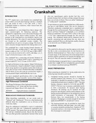
INTRODUCTION<br />
The starting system is designed to provide the vehicle<br />
operator with a convenient, efficient and reliable means of<br />
cranking and starting the internal combustion engine used to<br />
power the vehicle and all of its accessory systems from within<br />
the safe and secure confines of the passenger compartment.<br />
The starting system consists of the following components:<br />
0 Battery<br />
Starter relay<br />
0 Starter motor (including an integral starter solenoid)<br />
0 Ignition switch<br />
0 Parkheutral position switch<br />
0 Wire harnesses and connections (including the battery<br />
cables).<br />
Operation<br />
The starting system components form two separate circuits.<br />
A high-amperage feed circuit that feeds the starter motor<br />
between 150 and 350 amperes, and a low-amperage control<br />
circuit that operates on less than 20 amperes. The highamperage<br />
feed circuit components include the battery,<br />
battery cables, the contact disc portion of the starter<br />
solenoid, and the starter motor. The low-amperage control<br />
circuit components include the ignition switch, the<br />
parkheutral position switch, the starter relay, the<br />
electromagnetic windings of the starter solenoid, and the<br />
connecting wire harness components.<br />
Battery voltage is supplied through the low-amperage<br />
control circuit to the coil battery terminal of the starter relay<br />
when the ignition switch is turned to the momentary Start<br />
position. The parkheutral position switch is installed in<br />
series between the starter relay coil ground terminal and<br />
ground. This normally open switch prevents the starter<br />
relay from being energized and the starter motor from<br />
operating unless the automatic transmission gear selector is<br />
in the Neutral or Park positions.<br />
When the starter relay coil is energized, the normally open<br />
relay contacts close. The relay contacts connect the relay<br />
Common feed terminal to the relay normally open<br />
terminal. The closed relay contacts energize the starter<br />
solenoid coil windings.<br />
The energized solenoid pull-in coil pulls in the solenoid<br />
Plunger. The solenoid plunger pulls the shift lever in the<br />
starter motor. This engages the starter overrunning clutch<br />
and pinion gear with the starter ring gear on the automatic<br />
transmission torque converter drive plate.<br />
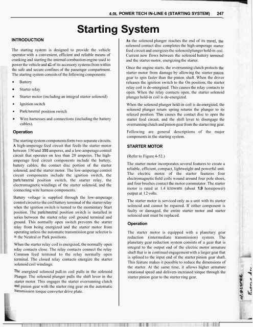
4.OL POWER TECH IN-LINE 6 (STARTING SYSTEM) 247<br />
<strong>Starting</strong> <strong>System</strong><br />
As the solenoid plunger reaches the end of its travel, the<br />
solenoid contact disc completes the high-amperage starter<br />
feed circuit and energizes the solenoid plunger hold-in coil.<br />
Current now flows between the solenoid battery terminal<br />
and the starter motor, energizing the starter.<br />
Once the engine starts, the overrunning clutch protects the<br />
starter motor from damage by allowing the starter pinion<br />
gear to spin faster than the pinion shaft. When the driver<br />
releases the ignition switch to the On position, the starter<br />
relay coil is de-energized. This causes the relay contacts to<br />
open. When the relay contacts open, the starter solenoid<br />
plunger hold-in coil is de-energized.<br />
When the solenoid plunger hold-in coil is de-energized, the<br />
solenoid plunger return spring returns the plunger to its<br />
relaxed position. This causes the contact disc to open the<br />
starter feed circuit, and the shift lever to disengage the<br />
overrunning clutch and pinion gear from the starter ring gear.<br />
Following are general descriptions of the major<br />
components in the starting system.<br />
STARTER MOTOR<br />
(Refer to Figure 4-52.)<br />
The starter motor incorporates several features to create a<br />
reliable, efficient, compact, lightweight and powerful unit.<br />
The electric motor of the starter features four<br />
electromagnetic field coils wound around four pole shoes,<br />
and four brushes contact the motor commutator. The starter<br />
motor is rated at 1.4 kilowatts (about 1.9 horsepower)<br />
output at 12 volts.<br />
The starter motor is serviced only as a unit with its starter<br />
solenoid and cannot be repaired. If either component is<br />
faulty or damaged, the entire starter motor and starter<br />
solenoid unit must be replaced.<br />
Operation<br />
The starter motor is equipped with a planetary gear<br />
reduction (intermediate transmission) system. The<br />
planetary gear reduction system consists of a gear that is<br />
integral to the output end of the electric motor armature<br />
shaft that is in continual engagement with a larger gear that<br />
is splined to the input end of the starter pinion gear shaft.<br />
This feature makes it possible to reduce the dimensions of<br />
the starter. At the same time, it allows higher armature<br />
rotational speed and delivers increased torque through the<br />
starter pinion gear to the starter ring gear.
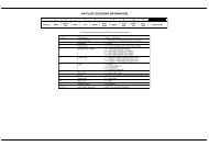
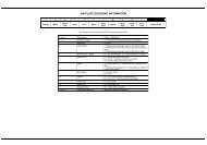
248 MOPAR PERFORMANCE PARTS<br />
1<br />
Starter Motor and Solenoid<br />
Manufacturer<br />
Mitsubishi<br />
Engine Application 2.5L, 4.0L<br />
2.5L 1.2 Kilowatt (1.6 Horsepower)<br />
Power Rating<br />
4.0L - 1.4 Kilowatt (1.9 Horsepower)<br />
Voltaae I 12 Volts I<br />
"<br />
Number of Fields 4<br />
Number of Poles 4<br />
Number of Brushes 4<br />
nrive -...- Tvne<br />
Planetarv Gear Reduction<br />
.,r-<br />
I<br />
" -<br />
Free Running Test Maximum Amperage Draw<br />
90 Amperes<br />
Free Running Test Minimum Speed<br />
2.5L 2600 rpm<br />
4.0L - 2500 rpm<br />
Solenoid Closina - Maximum Voltage - Required<br />
7.8 volts<br />
Free Runnina Test Voltaae I 11.2 Volts I<br />
2.5L - 130 Amperes<br />
4.0L - 160 Amperes<br />
*Cranking Amperage Draw Test<br />
I<br />
*Test at operating temperature. Cold engine, tight (new) engine, or heavy oil will increase starter amperage draw.<br />
Figure 4 - 52<br />
The starter motor is activated by an integral heavy duty<br />
starter solenoid switch mounted to the overrunning clutch<br />
housing. This electromechanical switch connects and<br />
disconnects the feed of battery voltage to the starter motor<br />
and actuates a shift fork that engages and disengages the<br />
starter pinion gear with the starter ring gear.<br />
The starter motor uses an overrunning clutch and starter<br />
pinion gear unit to engage and drive a starter ring gear that<br />
is integral to the torque converter drive plate mounted on<br />
the rear crankshaft flange.<br />
STARTER RELAY<br />
The starter relay is an electromechanical device that<br />
switches battery current to the pull-in coil of the starter<br />
solenoid when the ignition switch is turned to the Start<br />
position. The starter relay is located in the Power<br />
Distribution Center (PDC) in the engine compartment. See<br />
the fuse and relay layout label affixed to the inside surface<br />
of the PDC cover for starter relay identification and<br />
location. The starter relay cannot be repaired or adjusted<br />
and, if faulty or damaged, it must be replaced.<br />
BAlTERY<br />
It is very important that the battery be fully charged in<br />
racing applications with an electronic ignition. A volt meter<br />
should be used to check the battery voltage before the<br />
vehicle is raced. The voltage should not be allowed to drop<br />
below 12.0 volts. Lower voltage will cause poor ignition<br />
performance such as misfires and will result in slowing the<br />
vehicle down. It may also cut down on the electric fuel<br />
pump's efficiency.<br />
Brass Battery Terminals<br />
Here's a variety of brass terminals in different styles that<br />
offer maximum conductivity. Feature positive threaded<br />
attachments. Designed for large gauge wire used in battery<br />
relocation kits with features best liked and required by<br />
racers.<br />
P4349575<br />
P4349576<br />
P4349577<br />
P4349578<br />
P4349579<br />
P4349580<br />
Battery terminal with left or right cable<br />
connection - 1 gauge wire.<br />
Ring terminal, 3/8" eye - 1 gauge .wire.<br />
Battery terminal with left or right cable<br />
connection - 4 gauge wire.<br />
Ring terminal, 318" eye - 4 gauge wire.<br />
Quick disconnect "positive" battery<br />
terminal with 318" stud.<br />
Quick disconnect "negative" battery<br />
terminal with 318" stud.
4.0L POWER TECH IN-LINE 6 (STARTING SYSTEM) 249<br />
Battery Relocation<br />
Most race vehicles begin life with the battery in the<br />
engine compartment.<br />
Mounting the battery in the trunk of a RWD race vehicle<br />
helps by shifting weight over the drive wheels (improving<br />
traction) and by making the engine compartment less<br />
cluttered. But there's more to a trunk mounted battery kit<br />
than just putting the battery in the trunk. Physically moving<br />
the battery is easy. The problem is that the battery must still<br />
operate the engine's ignition and fuel delivery systems, and<br />
with the battery eight feet away from the ignition system<br />
(usually a high output electronic race unit), minimizing<br />
voltage drop is critical.<br />
To minimize voltage drop, the Mopar Performance Parts<br />
trunk mounted battery kit (P4349500) uses #1 gauge wire,<br />
while the competition uses #4 gauge. The smaller the gauge<br />
number the bigger the wire size. The bigger the wire size<br />
the less voltage drop occurs. To provide the best electrical<br />
conductor available, Mopar Performance Parts supplies<br />
copper wire-the competition uses aluminum. Copper is a<br />
better electrical conductor than aluminum. The better the<br />
conductor, the less voltage drop occurs in the same<br />
distance; that is, trunk to engine compartment. Handcrimped<br />
terminals can lead to problems such as voltage<br />
losses, loose connections, and so on. That's why the Mopar<br />
Performance Parts cable has factory-installed threaded<br />
brass terminals.<br />
Some people feel that a full length ground cable is required.<br />
This is acceptable, but it adds a lot of weight and isn't<br />
necessary. The engine is already grounded from the block<br />
to the firewall of the body/frame (unibody). Check to be<br />
sure. The Mopar Performance Parts package includes a<br />
ground strap to ground the battery to the frame in the trunk<br />
area. The Mopar Performance Parts package also includes<br />
many convenience items such as starter to relay and<br />
solenoid wires, terminals, firewall grommets, and battery<br />
cover. Other kits don't include these items. However, it<br />
does not include a battery.<br />
Trunk Mounted Battery Kit<br />
This improved kit is designed for moving the battery to<br />
the trunk. Improves weight distribution which is so<br />
important for drag racers. It means less clutter in the<br />
engine compartment, and helps provide better traction. It<br />
will even contribute to improved braking and less<br />
understeer in hard turns for oval trackers and rallyers. Kit<br />
will fit nearly any vehicle. Does not include battery.<br />
P4349500<br />
Trunk mounted battery kit.<br />
i<br />
I I IP I 1 I I I II I' ' 1'<br />
I1 1 I 1 I