Mechanical Piping
Gruvlok catalog - Anvil International
Gruvlok catalog - Anvil International

You also want an ePaper? Increase the reach of your titles
YUMPU automatically turns print PDFs into web optimized ePapers that Google loves.
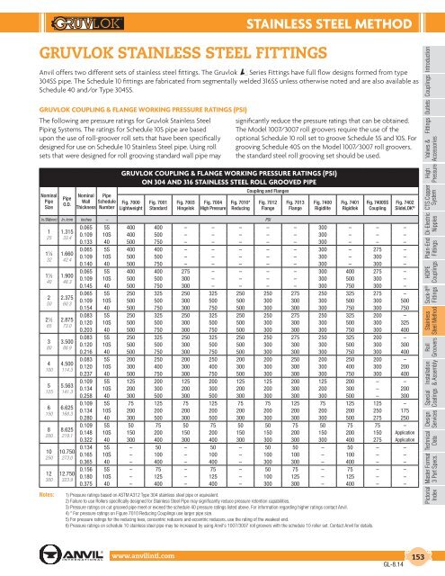
STAINLESS STEEL METHOD<br />
GRUVLOK STAINLESS STEEL FITTINGS<br />
Anvil offers two different sets of stainless steel fittings. The Gruvlok Series Fittings have full flow designs formed from type<br />
304SS pipe. The Schedule 10 fittings are fabricated from segmentally welded 316SS unless otherwise noted and are also available as<br />
Schedule 40 and/or Type 304SS.<br />
Introduction<br />
Couplings<br />
GRUVLOK COUPLING & FLANGE WORKING PRESSURE RATINGS (PSI)<br />
The following are pressure ratings for Gruvlok Stainless Steel<br />
<strong>Piping</strong> Systems. The ratings for Schedule 10S pipe are based<br />
upon the use of roll-groover roll sets that have been specifically<br />
designed for use on Schedule 10 Stainless Steel pipe. Using roll<br />
sets that were designed for roll grooving standard wall pipe may<br />
significantly reduce the pressure ratings that can be obtained.<br />
The Model 1007/3007 roll groovers require the use of the<br />
optional Schedule 10 roll set to groove Schedule 5S and 10S. For<br />
grooving Schedule 40S on the Model 1007/3007 roll groovers,<br />
the standard steel roll grooving set should be used.<br />
Outlets<br />
Fittings<br />
Valves &<br />
Accessories<br />
GRUVLOK COUPLING & FLANGE WORKING PRESSURE RATINGS (PSI)<br />
ON 304 AND 316 STAINLESS STEEL ROLL GROOVED PIPE<br />
High<br />
Pressure<br />
Nominal<br />
Pipe<br />
Size<br />
Pipe<br />
O.D.<br />
Nominal<br />
Wall<br />
Thickness<br />
Pipe<br />
Schedule<br />
Number<br />
Fig. 7000<br />
Lightweight<br />
Fig. 7001<br />
Standard<br />
Fig. 7003<br />
Hingelok<br />
Fig. 7004<br />
High Pressure<br />
Fig. 7010*<br />
Reducing<br />
Coupling and Flanges<br />
Fig. 7012<br />
Flange<br />
Fig. 7013<br />
Flange<br />
Fig. 7400<br />
Rigidlite<br />
Fig. 7401<br />
Rigidlok<br />
Fig. 7400SS<br />
Coupling<br />
Fig. 7402<br />
SlideLOK ®<br />
CTS Copper<br />
System<br />
In./DN(mm) In./mm Inches – PSI<br />
1<br />
25<br />
1 1 ⁄4<br />
32<br />
1 1 ⁄2<br />
40<br />
2<br />
50<br />
2 1 ⁄2<br />
65<br />
3<br />
80<br />
4<br />
100<br />
5<br />
125<br />
6<br />
150<br />
8<br />
200<br />
10<br />
250<br />
12<br />
300<br />
Notes:<br />
1.315<br />
33.4<br />
1.660<br />
42.4<br />
1.900<br />
48.3<br />
2.375<br />
60.3<br />
2.875<br />
73.0<br />
3.500<br />
88.9<br />
4.500<br />
114.3<br />
5.563<br />
141.3<br />
6.625<br />
168.3<br />
8.625<br />
219.1<br />
10.750<br />
273.0<br />
12.750<br />
323.9<br />
0.065 5S 400 400 – – – – – 300 – – –<br />
0.109 10S 400 500 – – – – – 300 – – –<br />
0.133 40 500 750 – – – – – 300 – – –<br />
0.065 5S 400 400 – – – – – 300 – 275 –<br />
0.109 10S 500 500 – – – – – 300 – 300 –<br />
0.140 40 500 750 – – – – – 300 – 300 –<br />
0.065 5S 400 400 275 – – – – 300 400 275 –<br />
0.109 10S 500 500 300 – – – – 300 500 300 –<br />
0.145 40 500 750 300 – – – – 300 750 300 –<br />
0.065 5S 250 325 250 325 250 250 275 250 325 275 –<br />
0.109 10S 500 500 300 500 500 300 300 300 500 300 500<br />
0.154 40 500 750 300 750 500 300 300 300 750 300 750<br />
0.083 5S 250 325 250 325 250 250 275 250 325 200 –<br />
0.120 10S 500 500 300 500 500 300 300 300 500 300 325<br />
0.203 40 500 750 300 750 500 300 300 300 750 300 400<br />
0.083 5S 250 325 250 325 250 250 275 250 325 200 –<br />
0.120 10S 500 500 300 500 500 300 300 300 500 300 300<br />
0.216 40 500 750 300 750 500 300 300 300 750 300 400<br />
0.083 5S 200 250 200 250 200 200 250 200 250 200 –<br />
0.120 10S 300 400 300 400 300 300 300 300 400 300 200<br />
0.237 40 500 750 300 750 500 300 300 300 750 300 400<br />
0.109 5S 125 200 125 200 125 125 200 125 200 – –<br />
0.134 10S 200 300 200 300 200 200 300 200 300 – 200<br />
0.258 40 300 500 300 500 300 300 300 300 500 – 300<br />
0.109 5S 75 125 75 125 75 75 125 75 125 125 –<br />
0.134 10S 200 200 200 200 200 200 200 200 200 250 175<br />
0.280 40 300 500 300 500 300 300 300 300 500 275 250<br />
0.109 5S 50 75 50 75 50 50 75 50 75 75 –<br />
0.148 10S 150 200 150 200 150 150 200 150 200 150 Application<br />
0.322 40 300 400 300 400 300 300 300 300 400 275 Application<br />
0.134 5S – 50 – 50 – 50 50 – 50 – –<br />
0.165 10S – 100 – 100 – 100 100 – 100 – –<br />
0.365 40 – 400 – 400 – 300 300 – 400 – –<br />
0.156 5S – 75 – 75 – 50 75 – 75 – –<br />
0.180 10S – 125 – 125 – 100 125 – 125 – –<br />
0.375 40 – 400 – 400 – 300 300 – 400 – –<br />
1) Pressure ratings based on ASTM A312 Type 304 stainless steel pipe or equivalent.<br />
2) Failure to use Rollers specifically designed for Stainless Steel Pipe may significantly reduce pressure retention capabilities.<br />
3) Pressure ratings on cut grooved pipe meet or exceed the schedule 40 pressure ratings listed above. For information regarding higher ratings contact Anvil.<br />
4) * For pressure ratings on Figure 7010 Reducing Couplings use larger pipe size.<br />
5) For pressure ratings for the reducing tees, concentric reducers and eccentric reducers, use the rating of the weakest end.<br />
6) Pressure ratings on schedule 10 stainless steel pipe may be increased by using Anvil's 1007/3007 roll groovers with the schedule 10 roller set. Contact Anvil for details.<br />
Di-Electric<br />
Nipples<br />
Plain-End<br />
Fittings<br />
HDPE<br />
Couplings<br />
Sock-It ®<br />
Fittings<br />
Stainless<br />
Steel Method<br />
Roll<br />
Groovers<br />
Installation<br />
& Assembly<br />
Special<br />
Coatings<br />
Design<br />
Services<br />
Technical<br />
Data<br />
Master Format<br />
3 Part Specs.<br />
Pictorial<br />
Index<br />
www.anvilintl.com 153<br />
GL-8.14