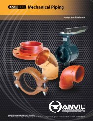
Mechanical Piping
Gruvlok catalog - Anvil International
Gruvlok catalog - Anvil International

Create successful ePaper yourself
Turn your PDF publications into a flip-book with our unique Google optimized e-Paper software.
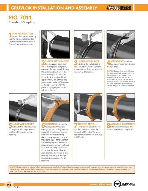
GRUVLOK INSTALLATION AND ASSEMBLY<br />
FIG. 7011<br />
Standard Coupling<br />
PIPE PREPARATION<br />
1 Inspect the pipe ends making<br />
sure the criteria, in the Gruvlok<br />
Large Diameter Pipe Roll and Cut<br />
Groove Specifications, are met.<br />
GASKET INSTALLATION<br />
2 Turn the gasket inside out<br />
and slide the gasket completely<br />
over one of the pipe ends. Turning<br />
the gasket inside out will reduce<br />
the stretching necessary to put<br />
the gasket into position. Ideally,<br />
approximately 75% of the pipe’s<br />
gasket-sealing surface, (Dimension<br />
A) should be visible when the<br />
gasket is in proper position. This<br />
will aid in step 4.<br />
LUBRICATE GASKET<br />
3 Lubricate the gasket sealing<br />
lips. The use of Gruvlok lubricants<br />
ensures compatibility between the<br />
lubricant and the gasket.<br />
ALIGNMENT—Pull the<br />
4 two pipes into contact aligning<br />
the pipe ends.<br />
CAUTION: Be careful not to pinch fingers<br />
during this step. Working your way around<br />
the circumference of the pipe, flip the<br />
gasket toward the pipe end so that the<br />
proper side is facing out. The end of this<br />
procedure will result in the gasket snapping<br />
into place. Position the gasket centrally<br />
between the grooves of the two pipe ends.<br />
5LUBRICATE GASKET<br />
Lubricate the exterior surface<br />
of the gasket. This helps prevent<br />
pinching of the gasket during<br />
assembly.<br />
HOUSINGS—Secure the<br />
6 housings about the pipes<br />
making sure the coupling keys are<br />
engaged in the pipe end grooves.<br />
Hint: For horizontal assembly,<br />
place housing segment on top of<br />
the pipe to support the weight of<br />
the housing segment. Secure the<br />
adjacent housing with an oval neck<br />
track bolt and heavy hex nut and<br />
then rotate the secured housings,<br />
again balancing the weight of the<br />
housings on the top of the pipe.<br />
Continue this procedure for all<br />
segments.<br />
TIGHTEN NUTS—<br />
7 Firmly torque each bolt. The<br />
specified minimum torque for<br />
each nut is 600 ft.-lbs. The specified<br />
maximum torque for each nut<br />
is 800 ft.-lbs.<br />
ASSEMBLY IS COMPLETE<br />
8 Installation of the Figure 7011<br />
Standard Coupling is completed.<br />
CAUTION: Proper torquing of coupling bolts is required to obtain specified performance. Over torquing the bolts may result in damage to the bolt and/or casting which could result in pipe<br />
joint separation. Under torquing the bolts may result in lower pressure retention capabilities, lower bend load capabilities, joint leakage and pipe joint separation. Pipe joint separation may<br />
result in significant property damage and serious injury.<br />
168<br />
GL-3.14<br />
www.anvilintl.com