STRONG-TIE
SAFETY BOLT - VJ Technology
SAFETY BOLT - VJ Technology

Create successful ePaper yourself
Turn your PDF publications into a flip-book with our unique Google optimized e-Paper software.
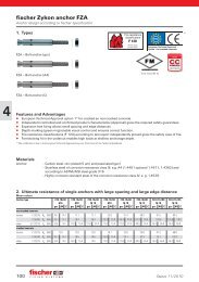
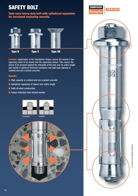
SAFETY BOLT<br />
Twin-cone heavy duty bolt with cylindrical expansion<br />
for increased anchoring security.<br />
Type B Type S Type SK<br />
Function: Application of the installation torque causes the anchor’s two<br />
opposing cones to be drawn into the expansion sleeve. This causes the<br />
sleeve to be pressed against the sidewalls of the hole over its entire length<br />
and results in optimum frictional resistance and high load capacity in<br />
cracked and non-cracked concrete.<br />
Benefits:<br />
● High capacity in cracked and non-cracked concrete<br />
● Cylindrical expansion of sleeve over entire length<br />
● Solid all-steel construction<br />
● Torque indication from domed washer<br />
Uninstalled<br />
Installed<br />
C-SL-2009E ©2009 SIMPSON <strong>STRONG</strong>-<strong>TIE</strong> <strong>TIE</strong> ®<br />
20
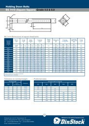
Expansion Anchor Systems<br />
SAFETY BOLT<br />
CONSTRUCTION:<br />
B<br />
S<br />
SK<br />
with hex nut, domed washer<br />
and threaded stud<br />
with hex head screw and domed<br />
washer<br />
with countersunk headed screw<br />
MATERIAL:<br />
Grade 8.8 carbon steel, zinc plated and blue passivated<br />
A4-80 stainless steel (Type B), A4-70 stainless steel (Type S, SK)<br />
BASE MATERIAL:<br />
Cracked and non-cracked concrete: C20/25 to C50/60<br />
APPROVAL:<br />
ETA-06/0108 – Option 1 – Carbon steel, zinc plated<br />
LOAD RANGE:<br />
Tension:<br />
Shear:<br />
N perm<br />
= 2.4 - 48.9 [kN]<br />
V perm<br />
= 5.2 - 80.6 [kN]<br />
R 120<br />
PRODUCT RANGE:<br />
B: M6 – M20, carbon steel, zinc plated and blue passivated / A4 stainless steel<br />
S: M6 – M20, carbon steel, zinc plated and blue passivated / M6 – M12, A4 stainless steel<br />
SK: M6 – M16, carbon steel, zinc plated and blue passivated / M6 – M12, A4 stainless steel<br />
APPLICATIONS:<br />
Steel construction<br />
Railing<br />
Gates<br />
Lifting systems<br />
Cable trays<br />
Machines<br />
Facades<br />
Base plates<br />
BENEFITS:<br />
Cylindrical expansion with optimal friction resistance<br />
Higher anchoring intensity from twin-cone design<br />
Torque indication from domed washer<br />
PRODUCT DESCRIPTION:<br />
Twin-cone sleeve anchor for high loads<br />
Torque-controlled mechanical anchor<br />
Solid, all-steel construction<br />
INSTALLATION:<br />
Through-fix installation<br />
C-SL-2009E ©2009 SIMPSON <strong>STRONG</strong>-<strong>TIE</strong> ®<br />
90°<br />
Drill hole Clean hole (blowing) Insert anchor<br />
through fixture<br />
Apply recommended<br />
fastening torque with a<br />
calibrated torque-wrench<br />
21
Expansion Anchor Systems<br />
SAFETY BOLT<br />
Carbon steel, zinc plated<br />
SAFETY BOLT B<br />
Threaded stud with hex nut and domed washer<br />
Material: Grade 8.8 carbon steel, zinc plated and blue passivated<br />
Approvals: ETA-06/0108 – Option 1<br />
New<br />
Type<br />
Old<br />
Type<br />
Order<br />
Code<br />
Thread<br />
Size<br />
Ø x<br />
Depth of<br />
Drilled Hole<br />
Max.<br />
Fixture<br />
Thickness<br />
Ø Fixture<br />
Hole<br />
Eff.<br />
Embedment<br />
Depth<br />
Total<br />
Length<br />
Weight<br />
Box<br />
Quantity<br />
d o x h 1 t fi x d f h ef L<br />
[mm] [mm] [mm] [mm] [mm] [mm] [kg/100 pcs] [pcs]<br />
B M6-10/45/5 B 10/20 LB0610045005 M6 10 x 60 5 12 45 70 2.7 50<br />
B M6-10/45/15 B 10/35 LB0610045015 M6 10 x 60 15 12 45 80 3.4 50<br />
B M6-10/45/40 B 10/60 LB0610045040 M6 10 x 60 40 12 45 105 4.6 50<br />
B M8-12/55/5 B 12/25 LB0812055005 M8 12 x 70 5 14 55 85 5.8 25<br />
B M8-12/55/15 B 12/40 LB0812055015 M8 12 x 70 15 14 55 95 7.0 25<br />
B M8-12/55/40 B 12/65 LB0812055040 M8 12 x 70 40 14 55 120 9.0 25<br />
B M8-12/55/65 B 12/90 LB0812055065 M8 12 x 70 65 14 55 145 10.6 25<br />
B M8-12/55/100 B 12/125 LB0812055100 M8 12 x 70 100 14 55 180 12.7 25<br />
B M10-15/70/5 B 15/30 LB1015070005 M10 15 x 85 5 17 70 100 11.0 25<br />
B M10-15/70/15 B 15/45 LB1015070015 M10 15 x 85 15 17 70 110 12.8 25<br />
B M10-15/70/40 B 15/70 LB1015070040 M10 15 x 85 40 17 70 135 16.0 10<br />
B M10-15/70/65 B 15/95 LB1015070065 M10 15 x 85 65 17 70 160 18.5 10<br />
B M10-15/70/100 B 15/120 LB1015070100 M10 15 x 85 100 17 70 195 22.0 10<br />
B M12-20/80/5 B 20/35 LB1220080005 M12 20 x 100 5 21 80 120 20.8 10<br />
B M12-20/80/15 B 20/50 LB1220080015 M12 20 x 100 15 21 80 130 24.8 10<br />
B M12-20/80/40 B 20/75 LB1220080040 M12 20 x 100 40 21 80 155 29.0 10<br />
B M12-20/80/65 B 20/100 LB1220080065 M12 20 x 100 65 21 80 180 33.5 10<br />
B M12-20/80/100 B 20/135 LB1220080100 M12 20 x 100 100 21 80 215 39.8 20<br />
B M16-25/100/5 B 25/40 LB1625100005 M16 25 x 125 5 26 100 150 43.4 5<br />
B M16-25/100/15 B 25/55 LB1625100015 M16 25 x 125 15 26 100 160 48.4 5<br />
B M16-25/100/40 B 25/80 LB1625100040 M16 25 x 125 40 26 100 185 56.7 5<br />
B M16-25/100/65 B 25/105 LB1625100065 M16 25 x 125 65 26 100 210 63.6 10<br />
B M16-25/100/100 B 25/130 LB1625100100 M16 25 x 125 100 26 100 245 75.0 10<br />
B M20-30/125/15* B 30/65 B2030125015 M20 30 x 150 15 32 125 180 85.9 5<br />
B M20-30/125/40* B 30/90 B2030125040 M20 30 x 150 40 32 125 205 96.7 5<br />
B M20-30/125/65* B 30/115 B2030125065 M20 30 x 150 65 32 125 230 107.6 5<br />
B M20-30/125/100* B 30/150 B2030125100 M20 30 x 150 100 32 125 265 122.0 5<br />
Custom lengths available on request.<br />
*Not included in approval.<br />
C-SL-2009E ©2009 SIMPSON <strong>STRONG</strong>-<strong>TIE</strong> ®<br />
22
Expansion Anchor Systems<br />
SAFETY BOLT TECHNICAL DATA<br />
Carbon steel, zinc plated<br />
Permissible loads for single anchors with no influencing edge distances or spacings. Loads are calculated using partial safety factors from ETAG 001<br />
and the characteristic anchor and installation data from this catalogue.<br />
Design calculations shall follow the requirements of ETA-06/0108.<br />
Material: Carbon steel, Grade 8.8, zinc plated and blue passivated<br />
Thread size M6 M8 M10 M12 M16 M20 7)<br />
Effective embedment depth (h ef ) [mm] 45 55 70 80 100 125<br />
Type B... M6-10/45/… M8-12/55/… M10-15/70/… M12-20/80/… M16-25/100/… M20-30/125/…<br />
Permissible tension loads 1)<br />
N perm<br />
Cracked<br />
concrete<br />
1) 2)<br />
Permissible shear loads<br />
Cracked<br />
concrete<br />
V perm<br />
C20/25 [kN] 2.4 3.6 7.6 12.3 17.1 18.6<br />
C30/37 [kN] 2.9 4.4 9.3 15.0 20.9 22.7<br />
C40/50 [kN] 3.4 5.0 10.7 17.3 24.2 26.2<br />
C50/60 [kN] 3.7 5.5 11.8 19.0 26.6 28.8<br />
Non-cracked C20/25 [kN] 3.0 4.8 9.5 17.2 24.0 31.6<br />
concrete 3) C30/37 [kN] 3.6 5.8 11.6 21.0 29.3 38.5<br />
C40/50 [kN] 4.2 6.7 13.4 24.2 33.8 44.5<br />
C50/60 [kN] 4.6 7.4 14.8 26.6 37.2 48.9<br />
C20/25 [kN] 5.2 7.0 20.1 24.5 34.3 49.2<br />
C30/37 [kN] 6.3 8.5 22.3 29.8 41.7 59.8<br />
C40/50 [kN] 7.3 9.9 22.3 34.3 48.5 61.6<br />
C50/60 [kN] 8.0 10.8 22.3 34.3 53.1 76.3<br />
Non-cracked C20/25 [kN] 7.2 9.8 22.3 34.3 48.0 68.9<br />
concrete 3) C30/37 [kN] 8.6 11.9 22.3 34.3 54.9 80.6<br />
C40/50 [kN] 8.6 13.8 22.3 34.3 54.9 80.6<br />
C50/60 [kN] 8.6 14.3 22.3 34.3 54.9 80.6<br />
1) 4)<br />
Permissible bending moments<br />
M perm [Nm] 6.9 17.1 34.3 60.0 152.0 296.6<br />
Spacings, edge distances and and member thicknesses<br />
Effective embedment depth h ef [mm] 45 55 70 80 100 125<br />
Characteristic spacing 5) s cr,N [mm] 135 165 210 240 300 375<br />
Minimum spacing s min [mm] 60 100 150 200 250 195<br />
Characteristic edge distance c cr,N [mm] 67.5 82.5 105 120 150 185<br />
Minimum edge distance 6) c min [mm] 80 100 150 200 250 350<br />
Minimum member thickness h min [mm] 100 110 140 160 200 250<br />
Installation data<br />
Drill hole diameter d 0 [mm] 10 12 15 20 25 30<br />
Drill hole depth h 1 [mm] 60 70 85 100 125 150<br />
Clearance<br />
hole in the<br />
fixture<br />
Through-fix<br />
anchorage<br />
Installation on<br />
threaded stud<br />
d f [mm] 12 14 17 21 26 32<br />
d f<br />
[mm] 7 9 12 14 18 22<br />
Width across flats sw [mm] 10 13 17 19 24 32<br />
Installation torque T inst [Nm] 8 15 40 70 115 300<br />
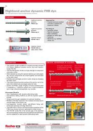
Installed anchor<br />
L<br />
sw<br />
T<br />
inst<br />
C-SL-2009E ©2009 SIMPSON <strong>STRONG</strong>-<strong>TIE</strong> ®<br />
d0<br />
h min<br />
h 1<br />
h ef<br />
t fix<br />
df<br />
Flattening of domed washer = visual installation check<br />
Untorqued<br />
1) The permissible loads have been calculated using the partial safety factors for resistances stated in the ETA-approval and a partial safety factor for actions of γ F = 1.4.<br />
The permissible loads are valid for unreinforced concrete and reinforced concrete with a rebar spacing s ≥ 15 cm and reinforced concrete with a rebar spacing s ≥ 10 cm if the rebar<br />
is 10 mm or smaller.<br />
2) The permissible shear loads are based on a single anchor without influencing concrete edges. For shear loads applied close to an edge (c ≤ 10 h ef or 60 d) concrete edge failure must be checked<br />
per ETAG 001, Annex C, design method A.<br />
3) Concrete is considered non-cracked when the tensile stress within the concrete is σ L + σ R ≤ 0. In the absence of detailed verification σ R = 3 N/mm² can be assumed (σ L equals the tensile stress<br />
within the concrete as a result of external loads, forces on anchors included).<br />
4) The permissible bending moments are only valid for the threaded stud (e.g. in case of a distance mounting).<br />
5) For spacings smaller than the characteristic values (i.e. s ≤ s cr,N ) a calculation per ETAG 001, Annex C, design method A shall be performed. For details, see ETA-06/0108.<br />
6) The actual edge distance shall not be less than the value of c min shown in the table.<br />
7) Size M20 is not included in the approval.<br />
Complete your designs more easily by downloading our LIEBIG anchor software from our home-page: www.simpson-liebig.com<br />
Torqued<br />
23
Expansion Anchor Systems<br />
SAFETY BOLT<br />
Carbon steel, zinc plated<br />
SAFETY BOLT S<br />
Hex head screw and domed washer<br />
Ausführung: Grade 8.8 carbon steel, zinc plated and blue passivated<br />
Approvals: ETA-06/0108 – Option 1<br />
New<br />
Type<br />
Old<br />
Type<br />
Order<br />
Code<br />
Thread<br />
Size<br />
Ø x<br />
Depth of<br />
Drilled Hole<br />
Max.<br />
Fixture<br />
Thickness<br />
Ø<br />
Fixture<br />
Hole<br />
Eff.<br />
Embedment<br />
Depth<br />
Total<br />
Length<br />
Weight<br />
Box<br />
Quantity<br />
d o x h 1 t fi x d f h ef L<br />
[mm] [mm] [mm] [mm] [mm] [mm] [kg/100 pcs] [pcs]<br />
S M6-10/45/5 S 10/20 LS0610045005 M6 10 x 60 5 12 45 70 2.7 50<br />
S M6-10/45/15 S 10/35 LS0610045015 M6 10 x 60 15 12 45 80 3.4 50<br />
S M6-10/45/40 S 10/60 LS0610045040 M6 10 x 60 40 12 45 105 4.6 50<br />
S M8-12/55/5 S 12/25 LS0812055005 M8 12 x 70 5 14 55 80 5.8 25<br />
S M8-12/55/15 S 12/40 LS0812055015 M8 12 x 70 15 14 55 90 7.0 25<br />
S M8-12/55/40 S 12/65 LS0812055040 M8 12 x 70 40 14 55 115 9.0 25<br />
S M10-15/70/5 S 15/30 LS1015070005 M10 15 x 85 5 17 70 95 11.0 25<br />
S M10-15/70/15 S 15/45 LS1015070015 M10 15 x 85 15 17 70 105 12.8 25<br />
S M10-15/70/40 S 15/70 LS1015070040 M10 15 x 85 40 17 70 130 16.0 10<br />
S M12-20/80/5 S 20/35 LS1220080005 M12 20 x 100 5 21 80 113 20.8 10<br />
S M12-20/80/15 S 20/50 LS1220080015 M12 20 x 100 15 21 80 123 24.8 10<br />
S M12-20/80/40 S 20/75 LS1220080040 M12 20 x 100 40 21 80 148 29.0 10<br />
S M16-25/100/5 S 25/40 LS1625100005 M16 25 x 125 5 26 100 145 43.4 5<br />
S M16-25/100/15 S 25/55 LS1625100015 M16 25 x 125 15 26 100 155 48.4 5<br />
S M16-25/100/40 S 25/80 LS1625100040 M16 25 x 125 40 26 100 180 56.7 5<br />
S M20-30/125/15* S 30/65 S2030125015 M20 30 x 150 15 32 125 180 85.9 5<br />
S M20-30/125/40* S 30/90 S2030125040 M20 30 x 150 40 32 125 205 96.7 5<br />
Custom lengths available on request.<br />
*Not included in approval.<br />
SAFETY BOLT SK<br />
Countersunk head screw<br />
Grade 8.8 carbon steel, zinc plated and blue passivated<br />
Approvals: ETA-06/0108 – Option 1<br />
New<br />
Type<br />
Old<br />
Type<br />
Order<br />
Code<br />
Thread<br />
Size<br />
Ø x<br />
Depth of<br />
Drilled Hole<br />
Max.<br />
Fixture<br />
Thickness<br />
Ø<br />
Fixture<br />
Hole<br />
Eff.<br />
Embedment<br />
Depth<br />
Total<br />
Length<br />
Weight<br />
Box<br />
Quantity<br />
d o x h 1 t fi x d f h ef L<br />
[mm] [mm] [mm] [mm] [mm] [mm] [kg/100 pcs] [pcs]<br />
SK M6-10/45/6 SK 10/20 LSK0610045006 M6 10 x 60 6 12 45 60 2.7 50<br />
SK M6-10/45/15 SK 10/35 LSK0610045015 M6 10 x 60 15 12 45 70 3.4 50<br />
SK M6-10/45/40 SK 10/60 LSK0610045040 M6 10 x 60 40 12 45 95 4.6 50<br />
SK M8-12/55/10 SK 12/25 LSK0812055010 M8 12 x 70 10 14 55 75 5.8 25<br />
SK M8-12/55/15 SK 12/40 LSK0812055015 M8 12 x 70 15 14 55 85 7.0 25<br />
SK M8-12/55/40 SK 12/65 LSK0812055040 M8 12 x 70 40 14 55 110 9.0 25<br />
SK M10-15/70/10 SK 15/30 LSK1015070010 M10 15 x 85 10 17 70 90 11.0 25<br />
SK M10-15/70/15 SK 15/45 LSK1015070015 M10 15 x 85 15 17 70 100 12.8 25<br />
SK M10-15/70/40 SK 15/70 LSK1015070040 M10 15 x 85 40 17 70 120 16.0 25<br />
SK M12-20/80/15 SK 20/50 LSK1220080015 M12 20 x 100 15 21 80 110 24.8 10<br />
SK M12-20/80/40 SK 20/75 LSK1220080040 M12 20 x 100 40 21 80 135 29.0 10<br />
SK M16-25/100/15 SK 25/55 LSK1625100015 M16 25 x 125 15 26 100 135 48.4 5<br />
SK M16-25/100/40 SK 25/80 LSK1625100040 M16 25 x 125 40 26 100 160 56.7 5<br />
Custom lengths available on request.<br />
C-SL-2009E ©2009 SIMPSON <strong>STRONG</strong>-<strong>TIE</strong> ®<br />
24
Expansion Anchor Systems<br />
SAFETY BOLT TECHNICAL DATA<br />
Carbon steel, zinc plated<br />
Permissible loads for single anchors with no influencing edge distances or spacings. Loads are calculated using partial safety factors from ETAG 001<br />
and the characteristic anchor and installation data from this catalogue.<br />
Design calculations shall follow the requirements of ETA-06/0108. .<br />
Material: Carbon steel, Grade 8.8, zinc plated and blue passivated<br />
Thread size M6 M8 M10 M12 M16 M20 6)<br />
Effective embedment depth (h ef ) [mm] 45 55 70 80 100 125<br />
Type S..., SK… M6-10/45/… M8-12/55/… M10-15/70/… M12-20/80/… M16-25/100/… M20-30/125/…<br />
Permissible tension loads 1)<br />
N perm<br />
Cracked<br />
concrete<br />
1) 2)<br />
Permissible shear loads<br />
V perm<br />
C20/25 [kN] 2.4 3.6 7.6 12.3 17.1 18.6<br />
C30/37 [kN] 2.9 4.4 9.3 15.0 20.9 22.7<br />
C40/50 [kN] 3.4 5.0 10.7 17.3 24.2 26.2<br />
C50/60 [kN] 3.7 5.5 11.8 19.0 26.6 28.8<br />
Non-cracked C20/25 [kN] 3.0 4.8 9.5 17.2 24.0 31.6<br />
concrete 3) C30/37 [kN] 3.6 5.8 11.6 21.0 29.3 38.5<br />
C40/50 [kN] 4.2 6.7 13.4 24.2 33.8 44.5<br />
C50/60 [kN] 4.6 7.4 14.8 26.6 37.2 48.9<br />
Cracked<br />
concrete<br />
C20/25 [kN] 5.2 7.0 20.1 24.5 34.3 49.2<br />
C30/37 [kN] 6.3 8.5 22.3 29.8 41.7 59.8<br />
C40/50 [kN] 7.3 9.9 22.3 34.3 48.5 69.6<br />
C50/60 [kN] 8.0 10.8 22.3 34.3 53.1 76.3<br />
Non-cracked C20/25 [kN] 7.2 9.8 22.3 34.3 48.0 68.9<br />
concrete 3) C30/37 [kN] 8.6 11.9 22.3 34.3 54.9 80.6<br />
C40/50 [kN] 8.6 13.8 22.3 34.3 54.9 80.6<br />
C50/60 [kN] 8.6 14.3 22.3 34.3 54.9 80.6<br />
Spacings, edge distances and and member thicknesses<br />
Effective embedment depth h ef [mm] 45 55 70 80 100 125<br />
Characteristic spacing 4) s cr,N [mm] 135 165 210 240 300 375<br />
Minimum spacing s min [mm] 60 100 150 200 250 195<br />
Characteristic edge distance c cr,N [mm] 67.5 82.5 105 120 150 185<br />
Minimum edge distance 5) c min [mm] 80 100 150 200 250 350<br />
Minimum member thickness h min [mm] 100 110 140 160 200 250<br />
Installation data<br />
Drill hole diameter d 0<br />
[mm] 10 12 15 20 25 30<br />
Drill hole depth h 1<br />
[mm] 60 70 85 100 125 150<br />
Clearance<br />
hole in the<br />
fixture<br />
Width across flat<br />
Installation torque<br />
Through-fix<br />
anchorage<br />
d f<br />
[mm] 12 14 17 21 26 32<br />
S sw [mm] 10 13 17 19 24 32<br />
SK sw [mm] 4 5 6 8 10 -<br />
S T inst<br />
[Nm] 8 20 60 90 170 300<br />
SK T inst<br />
[Nm] 12 20 60 90 190 -<br />
Installed anchor Countersunk washer<br />
L<br />
sw<br />
T<br />
inst<br />
C-SL-2009E ©2009 SIMPSON <strong>STRONG</strong>-<strong>TIE</strong> ®<br />
d0<br />
h min<br />
h 1<br />
h ef<br />
df<br />
Flattening of domed washer = visual installation check<br />
1) The permissible loads have been calculated using the partial safety factors for resistances stated in the ETA-approval and a partial safety factor for actions of γ F = 1.4.<br />
The permissible loads are valid for unreinforced concrete and reinforced concrete with a rebar spacing s ≥ 15 cm and reinforced concrete with a rebar spacing s ≥ 10 cm if the rebar<br />
is 10 mm or smaller.<br />
2) The permissible shear loads are based on a single anchor without influencing concrete edges. For shear loads applied close to an edge (c ≤ 10 h ef or 60d) concrete edge failure must be checked<br />
per ETAG 001, Annex C, design method A.<br />
3) Concrete is considered non-cracked when the tensile stress within the concrete is σ L + σ R ≤ 0. In the absence of detailed verification σ R = 3 N/mm² can be assumed (σ L equals the tensile stress<br />
within the concrete as a result of external loads, forces on anchors included).<br />
4) For spacings smaller than the characteristic values (i.e. s ≤ s cr,N ) a calculation per ETAG 001, Annex C, design method A shall be performed. For details, see ETA-06/0108.<br />
5) The actual edge distance shall not be less than the value of c min shown in the table.<br />
6) Size M20 is not included in the approval.<br />
Complete your designs more easily by downloading our LIEBIG anchor software from our home-page: www.simpson-liebig.com<br />
Size<br />
D<br />
[mm]<br />
d<br />
[mm]<br />
k<br />
[mm]<br />
M6 20 10 5,5<br />
M8 24 12 6,5<br />
M10 27 15 7<br />
M12 33 19 8<br />
M16 50 24 14<br />
t fix<br />
25
Expansion Anchor Systems<br />
SAFETY BOLT<br />
A4 stainless steel<br />
SAFETY BOLT B<br />
Threaded stud with hex nut and domed washer<br />
Material: A4-80 stainless steel<br />
New<br />
Type<br />
Old<br />
Type<br />
Order<br />
Code<br />
Thread<br />
Size<br />
Ø x<br />
Depth of<br />
Drilled Hole<br />
Max.<br />
Fixture<br />
Thickness<br />
Ø<br />
Fixture<br />
Hole<br />
Eff.<br />
Embedment<br />
Depth<br />
Total<br />
Length<br />
Weight<br />
Box<br />
Quantity<br />
d o x h 1 t fi x d f h ef L<br />
[mm] [mm] [mm] [mm] [mm] [mm] [kg/100 pcs] [pcs]<br />
B M6-10/45/5 A4 B 10/20 A4 B0610045005A4 M6 10 x 60 5 12 45 70 2.7 50<br />
B M6-10/45/15 A4 B 10/35 A4 B0610045015A4 M6 10 x 60 15 12 45 80 3.4 50<br />
B M6-10/45/40 A4 B 10/60 A4 B0610045040A4 M6 10 x 60 40 12 45 105 4.6 50<br />
B M8-12/55/5 A4 B 12/25 A4 B0812055005A4 M8 12 x 70 5 14 55 85 5.8 25<br />
B M8-12/55/15 A4 B 12/40 A4 B0812055015A4 M8 12 x 70 15 14 55 95 7.0 25<br />
B M8-12/55/40 A4 B 12/65 A4 B0812055040A4 M8 12 x 70 40 14 55 120 9.0 25<br />
B M10-15/70/5 A4 B 15/30 A4 B1015070005A4 M10 15 x 85 5 17 70 100 11.0 25<br />
B M10-15/70/15 A4 B 15/45 A4 B1015070015A4 M10 15 x 85 15 17 70 110 12.8 25<br />
B M10-15/70/40 A4 B 15/70 A4 B1015070040A4 M10 15 x 85 40 17 70 135 16.0 10<br />
B M12-20/80/5 A4 B 20/35 A4 B1220080005A4 M12 20 x 95 5 21 80 120 20.8 10<br />
B M12-20/80/15 A4 B 20/50 A4 B1220080015A4 M12 20 x 95 15 21 80 130 24.8 10<br />
B M12-20/80/40 A4 B 20/75 A4 B1220080040A4 M12 20 x 95 40 21 80 155 29.0 10<br />
B M16-25/100/15 A4 B 25/55 A4 B1625100015A4 M16 25 x 125 15 26 100 160 48.4 5<br />
B M16-25/100/40 A4 B 25/80 A4 B1625100040A4 M16 25 x 125 40 26 100 185 56.7 5<br />
B M20-30/125/40 A4 B 30/90 A4 B2030125040A4 M20 30 x 150 40 32 125 205 96.7 5<br />
Custom lengths available on request.<br />
SAFETY BOLT S<br />
Hex head screw and domed washer<br />
Material: A4-70 stainless steel<br />
New<br />
Type<br />
Old<br />
Type<br />
Order<br />
Code<br />
Thread<br />
Size<br />
Ø x<br />
Depth of<br />
Drilled Hole<br />
Max.<br />
Fixture<br />
Thickness<br />
Ø<br />
Fixture<br />
Hole<br />
Eff.<br />
Embedment<br />
Depth<br />
Total<br />
Length<br />
Weight<br />
Box<br />
Quantity<br />
d o x h 1 t fi x d f h ef L<br />
[mm] [mm] [mm] [mm] [mm] [mm] [kg/100 pcs] [pcs]<br />
S M6-10/45/15 A4 S 10/35 A4 S0610045015A4 M6 10 x 60 15 12 45 80 3.4 50<br />
S M6-10/45/40 A4 S 10/60 A4 S0610045040A4 M6 10 x 60 40 12 45 105 4.6 50<br />
S M8-12/55/15 A4 S 12/40 A4 S0812055015A4 M8 12 x 70 15 14 55 90 7.0 25<br />
S M8-12/55/40 A4 S 12/65 A4 S0812055040A4 M8 12 x 70 40 14 55 115 9.0 25<br />
S M10-15/70/15 A4 S 15/45 A4 S1015070015A4 M10 15 x 85 15 17 70 105 12.8 25<br />
S M10-15/70/40 A4 S 15/70 A4 S1015070040A4 M10 15 x 85 40 17 70 130 16.0 10<br />
S M12-20/80/15 A4 S 20/50 A4 S1220080015A4 M12 20 x 95 15 21 80 123 24.8 10<br />
S M12-20/80/40 A4 S 20/75 A4 S1220080040A4 M12 20 x 95 40 21 80 148 29.0 10<br />
Custom lengths available on request.<br />
SAFETY BOLT SK<br />
New<br />
Type<br />
Old<br />
Type<br />
Order<br />
Code<br />
Countersunk head screw<br />
Material: A4-70 stainless steel<br />
Thread<br />
Size<br />
Ø x<br />
Depth of<br />
Drilled Hole<br />
Max.<br />
Fixture<br />
Thickness<br />
Ø<br />
Fixture<br />
Hole<br />
Eff.<br />
Embedment<br />
Depth<br />
Total<br />
Length<br />
Weight<br />
Box<br />
Quantity<br />
d o x h 1 t fi x d f h ef L<br />
[mm] [mm] [mm] [mm] [mm] [mm] [kg/100 pcs] [pcs]<br />
SK M6-10/45/15 A4 SK 10/35 A4 SK0610045015A4 M6 10 x 60 15 12 45 70 3.4 50<br />
SK M6-10/45/40 A4 SK 10/60 A4 SK0610045040A4 M6 10 x 60 40 12 45 95 4.6 50<br />
SK M8-12/55/15 A4 SK 12/40 A4 SK0812055015A4 M8 12 x 70 15 14 55 85 7.0 25<br />
SK M8-12/55/40 A4 SK 12/65 A4 SK0812055040A4 M8 12 x 70 40 14 55 110 9.0 25<br />
SK M10-15/70/15 A4 SK 15/45 A4 SK1015070015A4 M10 15 x 85 15 17 70 100 12.8 25<br />
SK M10-15/70/40 A4 SK 15/70 A4 SK1015070040A4 M10 15 x 85 40 17 70 125 16.0 25<br />
SK M12-20/80/15 A4 SK 20/50 A4 SK1220080015A4 M12 20 x 95 15 21 80 110 24.8 10<br />
SK M12-20/80/40 A4 SK 20/75 A4 SK1220080040A4 M12 20 x 95 40 21 80 135 29.0 10<br />
Custom lengths available on request.<br />
C-SL-2009E ©2009 SIMPSON <strong>STRONG</strong>-<strong>TIE</strong> ®<br />
26
Expansion Anchor Systems<br />
SAFETY BOLT TECHNICAL DATA<br />
A4 stainless steel<br />
Permissible loads for single anchors with no influencing edge distances or spacings. Loads are calculated using partial safety factors from ETAG 001<br />
and the characteristic anchor and installation data from this catalogue.<br />
Material: A4-80 stainless steel (Type B), A4-70 stainless steel (Type S, SK)<br />
Thread size M6 M8 M10 M12 M16 M20<br />
Effective embedment depth (h ef ) [mm] 45 55 70 80 100 125<br />
Type B.... S…. SK… M6-10/45/… M8-12/55/… M10-15/70/… M12-20/80/… M16-25/100/… M20-30/125/…<br />
Permissible tension loads 1)<br />
Cracked<br />
concrete<br />
N perm<br />
C20/25 [kN] - - - 7.1 10.7 15.5<br />
C30/37 [kN] - - - 8.4 12.6 18.3<br />
C40/50 [kN] - - - 9.5 14.3 20.8<br />
C50/60 [kN] - - - 10.5 15.8 22.9<br />
Non-cracked C20/25 [kN] 3.2 4.3 7.1 10.7 16.0 23.2<br />
concrete 3) C30/37 [kN] 3.9 5.2 8.6 12.6 18.8 27.4<br />
C40/50 [kN] 4.5 6.1 10.0 14.3 21.4 31.1<br />
C50/60 [kN] 5.0 6.7 11.0 15.8 23.7 34.3<br />
Permissible shear loads 1) 2) B S/SK B S/SK B S/SK<br />
Cracked C20/25 [kN] - - - 20.5 20.5 28.6 28.6 39.9 39.9<br />
concrete C30/37 [kN] - - - 24.2 24.2 33.7 33.7 47.1 47.1<br />
C40/50 [kN] - - - 27.5 24.6 38.3 38.3 53.5 53.5<br />
V perm<br />
C50/60 [kN] - - - 28.9 24.6 42.3 41.5 59.1 59.1<br />
Non-cracked C20/25 [kN] 3.2 4.3 7.1 28.7 24.6 40.0 40.0 55.9 55.9<br />
concrete 3) C30/37 [kN] 3.9 5.2 8.6 28.9 24.6 47.2 41.5 66.0 61.6<br />
C40/50 [kN] 4.5 6.1 10.0 28.9 24.6 49.5 41.5 67.4 61.6<br />
C50/60 [kN] 5.0 6.7 11.0 28.9 24.6 49.5 41.5 67.4 61.6<br />
Permissible bending moments 1)4)<br />
M perm [Nm] 6.5 16.1 32.1 56.1 142.7 278.1<br />
Spacings, edge distances and and member thicknesses<br />
Effective embedment depth h ef [mm] 45 55 70 80 100 125<br />
Characteristic spacing 5) s cr, N [mm] 140 165 235 240 300 375<br />
Minimum spacing s min [mm] 140 165 235 120 150 195<br />
Characteristic edge distance c cr, N [mm] 80 120 165 120 150 195<br />
Minimum edge distance 6) c min [mm] 80 120 165 210 270 350<br />
Minimum member thickness h min [mm] 100 110 140 150 200 250<br />
Installation data<br />
Drill hole diameter d 0 [mm] 10 12 15 20 25 30<br />
Drill hole depth h 1 [mm] 60 70 85 95 125 150<br />
Clearance<br />
hole in the<br />
fixture<br />
Through-fix<br />
anchorage<br />
Installation on<br />
threaded stud<br />
d f [mm] 12 14 17 21 26 32<br />
d f<br />
[mm] 7 9 12 14 18 22<br />
B sw [mm] 10 13 17 19 24 30<br />
Width across flat S sw [mm] 10 13 17 19 - -<br />
SK sw [mm] 4 5 6 8 - -<br />
B T inst [Nm] 10 25 50 80 180 300<br />
Installation torque S T inst [Nm] 10 25 50 80 - -<br />
SK T inst [Nm] 10 25 50 80 - -<br />
Installed anchor Countersunk washer<br />
C-SL-2009E ©2009 SIMPSON <strong>STRONG</strong>-<strong>TIE</strong> ®<br />
Flattening of domed washer = visual installation check<br />
Size<br />
D<br />
[mm]<br />
d<br />
[mm]<br />
k<br />
[mm]<br />
M6 20 10 5,5<br />
M8 24 12 6,5<br />
M10 27 15 7<br />
M12 33 19 8<br />
1) The permissible loads have been calculated using partial safety factors for resistances and a partial safety factor for actions of γ F = 1.4.<br />
The permissible loads are valid for unreinforced concrete and reinforced concrete with a rebar spacing s ≥ 15 cm and reinforced concrete with a rebar spacing s ≥ 10 cm if the rebar<br />
is 10 mm or smaller.<br />
2) The permissible shear loads are based on a single anchor without influencing concrete edges. For shear loads applied close to an edge (c ≤ 10 h ef or 60d) concrete edge failure must be checked<br />
per ETAG 001, Annex C, design method A.<br />
3) Concrete is considered non-cracked when the tensile stress within the concrete is σ L + σ R ≤ 0. In the absence of detailed verification σ R = 3 N/mm² can be assumed (σ L<br />
equals the tensile stress<br />
within the concrete as a result of external loads, forces on anchors included).<br />
4) The permissible bending moments are only valid for the threaded stud (e.g. in case of a distance mounting).<br />
5) For spacings smaller than the characteristic values (i.e. s ≤ s cr,N ) a calculation per ETAG 001, Annex C, design method A shall be performed.<br />
6) The actual edge distance shall not be less than the value of c min shown in the table.<br />
Complete your designs more easily by downloading our LIEBIG anchor software from our home-page: www.simpson-liebig.com<br />
27