AP85040 - GT Development Corporation
AP85040 - GT Development Corporation
AP85040 - GT Development Corporation

Create successful ePaper yourself
Turn your PDF publications into a flip-book with our unique Google optimized e-Paper software.
<strong>GT</strong> <strong>Development</strong> <strong>Corporation</strong><br />
®<br />
Form No. 400-<br />
Rev.: A<br />
DCR 2304<br />
Incorp. By: M.Hillis<br />
Date: 07/17/07<br />
APPLICATION INSTRUCTION<br />
<strong>AP85040</strong><br />
SHEET 1 OF 4<br />
Title:<br />
Used on:<br />
APPLICATION INSTRUCTION, LACM AIR LINE ASSY<br />
5040-xxx-xx<br />
Written By: K. CURTIN Date: 7/17/07<br />
Lift Axle Control Module (LACM)<br />
Air Line Connections<br />
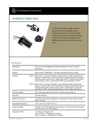
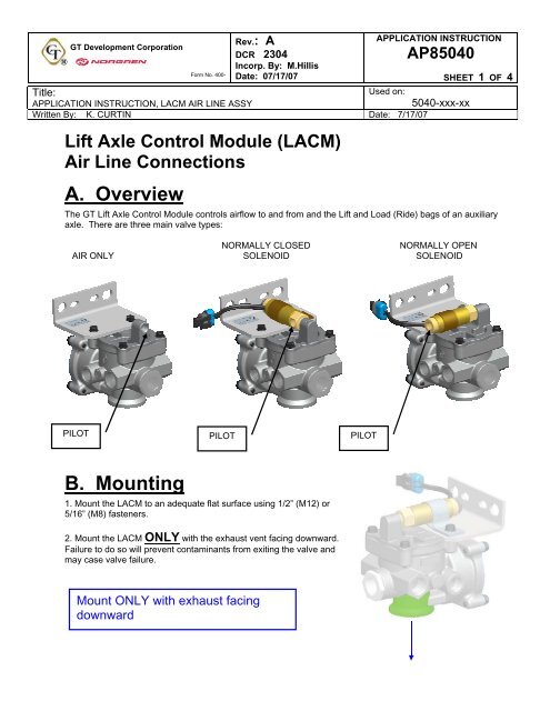
A. Overview<br />
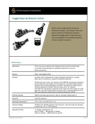
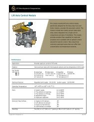
The <strong>GT</strong> Lift Axle Control Module controls airflow to and from and the Lift and Load (Ride) bags of an auxiliary<br />
axle. There are three main valve types:<br />
NORMALLY CLOSED NORMALLY OPEN<br />
AIR ONLY SOLENOID SOLENOID<br />
PILOT<br />
B. Mounting<br />
1. Mount the LACM to an adequate flat surface using 1/2” (M12) or<br />
5/16” (M8) fasteners.<br />
2. Mount the LACM ONLY with the exhaust vent facing downward.<br />
Failure to do so will prevent contaminants from exiting the valve and<br />
may case valve failure.<br />
Mount ONLY with exhaust facing<br />
downward<br />
PILOT PILOT
<strong>GT</strong> <strong>Development</strong> <strong>Corporation</strong><br />
®<br />
Form No. 400-<br />
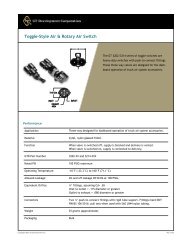
C. Air Connections<br />
Rev.: A<br />
DCR 2304<br />
Incorp. By: M.Hillis<br />
Date: 07/17/07<br />
All LACM versions have 4 main (plus an optional gauge<br />
port) air line connection locations.<br />
1. MAIN SUPPLY<br />
The Main Supply port is the connection to the Supply air reservoir<br />
(downstream of the pressure protection valve). <strong>GT</strong> recommends use<br />
of a 1/2” Supply line to ensure adequate airflow.<br />
Connect the Main supply to the axle’s<br />
air reservoir, downstream of the PPV.<br />
2. PILOT PORT (Control port)<br />
The Pilot port is the connection to the auxiliary axle regulated pilot.<br />
The pilot port is connected downstream of the auxiliary axle<br />
regulator. <strong>GT</strong> recommends use of a ¼” Pilot line. The Pilot is<br />
connected to the inlet per Section A above. (Normally Closed<br />
Solenoid shown)<br />
Connect the pilot port to the axle’s<br />
Load Bag Regulator.<br />
3. LOAD DELIVERY PORTS (2 per valve)<br />
The Load delivery ports are the connection from the LACM to the<br />
Load (Ride) Bags. One port is connected to each Load bag. <strong>GT</strong><br />
recommends use of 1/2” Load delivery lines to ensure adequate<br />
airflow.<br />
Connect the Load Delivery ports to<br />
the axle’s Load bags.<br />
APPLICATION INSTRUCTION<br />
<strong>AP85040</strong><br />
SHEET 2 OF 4
<strong>GT</strong> <strong>Development</strong> <strong>Corporation</strong><br />
®<br />
Form No. 400-<br />
Rev.: A<br />
DCR 2304<br />
Incorp. By: M.Hillis<br />
Date: 07/17/07<br />
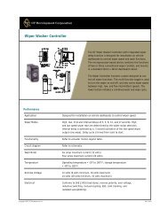
4. LIFT DELIVERY PORTS (2 per valve)<br />
The Lift delivery ports are the connection from the LACM to the Lift<br />
bags. One port is connected to each Lift bag. <strong>GT</strong> recommends use<br />
of 3/8” Lift delivery lines to ensure adequate airflow.<br />
Connect the Lift delivery ports to the<br />
axle’s Lift bags.<br />
5. (OPTIONAL) GAUGE PORT<br />
The optional Gauge port is common with the Load delivery ports.<br />
This port should be connected to the auxiliary axle’s Load bag air<br />
pressure gauge.<br />
Connect the Gauge port to the Load<br />
bag pressure gauge.<br />
D. Electrical Connection<br />
APPLICATION INSTRUCTION<br />
<strong>AP85040</strong><br />
SHEET 3 OF 4<br />
Solenoid equipped valves are either polarity sensitive or non-polarity sensitive. This characteristic can be<br />
confirmed by the colors of the wires:<br />
1. Polarity sensitive: 2. Non-Polarity sensitive:<br />
Black - Common<br />
Red - Positive<br />
Both White
<strong>GT</strong> <strong>Development</strong> <strong>Corporation</strong><br />
®<br />
Form No. 400-<br />
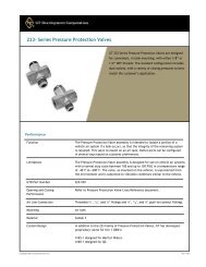
E. Typical Installation<br />
Rev.: A<br />
DCR 2304<br />
Incorp. By: M.Hillis<br />
Date: 07/17/07<br />
Solenoid LACM, w/o gauge port<br />
Pressure Protection Valve (PPV) not shown<br />
Typical PPV<br />
location<br />
REGULATOR<br />
ELECTRICAL CONNECTION<br />
TO CAB MOUNTED SWITCH<br />
APPLICATION INSTRUCTION<br />
<strong>AP85040</strong><br />
F. Pressure Protection Valve Replacement<br />
If kit is equipped with a replacement Pressure Protection<br />
Valve (PPV), replace the PPV supplying the auxiliary<br />
axle. The main supply line (1/2”) and pilot (1/4”) are<br />
connected to the PPV.<br />
Installation of the replacement PPV will ensure adequate<br />
airflow to the LACM.<br />
Replace the auxiliary axle PPV with<br />
the supplied unit.<br />
Load<br />
Bag<br />
Load<br />
Bag<br />
LACM<br />
Lift<br />
Bag<br />
Lift<br />
Bag<br />
SHEET 4 OF 4