ECE1336 Research Paper The Memristor
ECE1336 Research Paper: The Memristor
ECE1336 Research Paper: The Memristor

You also want an ePaper? Increase the reach of your titles
YUMPU automatically turns print PDFs into web optimized ePapers that Google loves.
<strong>ECE1336</strong> <strong>Research</strong> <strong>Paper</strong>: <strong>The</strong> <strong>Memristor</strong><br />
(Dec. 12 th , 2011)<br />
Andrew Shorten
Table of Contents<br />
Introduction ..................................................................................................................... 3<br />
Background ..................................................................................................................... 3<br />
<strong>The</strong> HP <strong>Memristor</strong> ........................................................................................................... 8<br />
Electrical Conductivity of Titanium Dioxide .................................................................... 11<br />
Anion Migration in Titanium Dioxide .............................................................................. 14<br />
Applications of the <strong>Memristor</strong> ........................................................................................ 18<br />
Report Summary ........................................................................................................... 21<br />
References .................................................................................................................... 22<br />
2
Introduction<br />
Every undergraduate electrical engineering student extensively studies three<br />
fundamental, two terminal circuit elements; the resistor, the capacitor and the inductor.<br />
Students are taught that every passive electrical circuit can be defined as a combination<br />
of these three fundamental elements. However, in 1971, Leon Chua, a young UC<br />
Berkeley Professor, hypothesized that mathematically, a fourth fundamental passive<br />
circuit element could exist. This report will examine Chua’s fourth circuit element, which<br />
he dubbed the <strong>Memristor</strong> and how it was finally constructed in 2008.<br />
Background<br />
Passive electrical circuits can be thought of as a set of relationships between four<br />
electromagnetic quantities, summarized in Table 1 [1]. Voltage can be defined as the<br />
change magnetic flux with respect to time. Current can be defined as the change in<br />
electric charge with respect to time. Resistance can be defined as a linear relationship<br />
between voltage and current. Capacitance can be defined as a linear relationship<br />
between voltage and electric charge. Inductance can be defined as a linear relationship<br />
between magnetic flux and current.<br />
Symbol<br />
v<br />
i<br />
q<br />
Φ<br />
Name<br />
Voltage<br />
Current<br />
Electric Charge<br />
Magnetic Flux<br />
Table 1: Basic Electromagnetic Quantities<br />
3
<strong>The</strong>se relationships can best be described mathematically in equations (1)-(5) below [2].<br />
Thus, the three fundamental circuit elements and the definitions of voltage and current<br />
are defined using almost all possible pairings between two items from Table 1. <strong>The</strong> only<br />
two electromagnetic quantities for which there are no pairings are magnetic flux and<br />
electric charge. Chua and his contemporaries knew of no existing physical process or<br />
electronic device that created this remaining relationship [1].<br />
(1) Definition of Current :<br />
(2) Definition of Voltage :<br />
(3) Definition of Resistance:<br />
(4) Definition of Capacitance:<br />
(5) Definition of Inductance:<br />
Identifying this omission, Chau mathematically defined a circuit element that would<br />
provide a relationship between magnetic flux and electric charge. Chua developed<br />
equation (6) in order to characterize this hypothetical electronic device [1].<br />
(6) Definition of New Circuit Element:<br />
As (6) is a little vague when attempting to ascertain qualitative features of this new<br />
device, some mathematical analysis is required. By integrating (6) and representing the<br />
right hand side as a function of electric charge (q), equation (7) is realized. Equation (7)<br />
expresses the fact that the magnetic flux of the device (φ) is a function of the cumulative<br />
electric charge that has passed through the device.<br />
(7)<br />
4
If equation (7) is differentiated with respect to time, equation (8) is realized.<br />
(8)<br />
Recognising the definitions of voltage and current from equations (1) and (2) above,<br />
equation (9) can be developed.<br />
(9)<br />
Furthermore, equation (10) is a simple way of expressing equation (9), identifying that<br />
the voltage and current of the device are related in a manner similar to that of<br />
resistance. However, this new device exhibits a resistance that is a function of the<br />
electric charge that has passed through the device [1].<br />
(10) ,<br />
Considering that this device must have a memory of the charge that has passed<br />
through it, (10) can be expressed as (11), where, instead of charge, a state variable w<br />
represents the current memory state of the device.<br />
(11)<br />
Thus, qualitatively, Chua’s new circuit element would have an electrical resistance that<br />
is a function of the amount of electric charge that has passed through its terminals.<br />
Furthermore, the device would exhibit memory; its resistance value would be retained<br />
even while not in use. Chua dubbed his new device the <strong>Memristor</strong>, a combination of the<br />
words memory and resistor. Chua then gave <strong>Memristor</strong> the circuit symbol found in the<br />
top left hand corner of Figure 1 [1].<br />
5
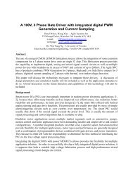
In order to help define this new circuit element, a figure known as the bowtie diagram,<br />
shown in Figure 1, is often employed. Figure 1 shows that the resistance of the new<br />
device changes with applied voltage and frequency, the memory characteristic of the<br />
device featuring prominently as a hysteretic curve. One important feature of the<br />
<strong>Memristor</strong> is that the hysteretic curve tightens as the applied ac frequency increases [1].<br />
Thus, for high frequencies, the resistance of the <strong>Memristor</strong> remains unchanged.<br />
Figure 1: <strong>Memristor</strong> Bowtie Diagram (Source: [3])<br />
Chua went on to hypothesize that these devices could have several applications in<br />
digital memory, analog electronics and neural networks. Furthermore, Chua showed<br />
that several passive and active circuit elements would be required in order to mimic the<br />
device’s behaviour, as shown in Figure 2.<br />
6
Figure 2: A <strong>Memristor</strong> Built From Other Circuit Elements (Source: [1])<br />
Nevertheless, while mathematically sound and very intriguing, Chua’s work had very<br />
little impact within the electrical engineering community. <strong>The</strong> three fundamental existing<br />
circuit elements can be easily and reliably constructed. A capacitor can be constructed<br />
from two parallel plate conductors. An inductor can be constructed from a coil of wire. A<br />
resistor can be constructed from a block of material exhibiting low electrical conductivity.<br />
At the time, nobody had observed a material or physical structure that exhibited the<br />
characteristics of a <strong>Memristor</strong>. Thus, Chau’s work sat in obscurity, a mathematical<br />
novelty with tremendous potential for real world applications. This situation remained<br />
until 2008, when a small research team at HP Labs used TiO2 to build Chua’s <strong>Memristor</strong><br />
[4].<br />
7
<strong>The</strong> HP <strong>Memristor</strong><br />
In 2008, a research team led by R.S. Williams working at HP Labs in Palo Alto, revealed<br />
that they had fabricated a device which behaved in a manner satisfying the<br />
requirements of Chua’s <strong>Memristor</strong> [4].<br />
<strong>The</strong> HP <strong>Memristor</strong>, as shown in Figure 3, is a device composed of thin films of TiO2 and<br />
TiO2-x placed between two platinum electrodes. This structure can be thought of as a<br />
continuous medium of TiO2 but with the TiO2-x region doped with oxygen vacancies.<br />
Thus, in the TiO2-x region, the ratio between titanium atoms and oxygen atoms has been<br />
altered such that there is less oxygen than in a regular TiO2 sample [4]. <strong>The</strong> width of the<br />
doped region is represented by w and the width of the entire structure is represented by<br />
D. An essential characteristic of this arrangement is that resistances of the doped and<br />
undoped regions differ significantly. As will be discussed below, TiO2-x exhibits a much<br />
lower electrical resistance than TiO2 [5]. In the extreme cases, the electrical resistance<br />
of the structure will produce either a high resistance or a low resistance corresponding<br />
to w being D or 0 respectively. <strong>The</strong> resistance of the device when w = D will be<br />
designated R ON and when w = 0 the resistance will be designated as R OFF. This<br />
convention is shown in Figure 4.<br />
Figure 3: Vertical Cross Section of the HP <strong>Memristor</strong> (Source: [6])<br />
8
Figure 4: Resistance Naming Convention (Source: [6])<br />
Given this naming convention, the entire resistance of the structure can be thought of as<br />
series combinations of two resistances, the values of which are dependant the value of<br />
w. This simplified structure is as shown in Figure 5.<br />
Figure 5: Effective Electrical Structure of the HP <strong>Memristor</strong> (Source: [6])<br />
(12) ( ( ))<br />
From Figure 5, the effective IV behaviour of the structure can be represented as<br />
equation (12) [6]. At first glance, this arrangement does not appear to be functionally<br />
different than a regular resistor; it appears to simply be a compound device made of two<br />
resistors. However, with an applied electric field, the oxygen vacancies behave rather<br />
strangely. <strong>The</strong> vacancies will drift from the doped region into the undoped region [6].<br />
This drift will increase the effective width of the doped region (w) at a rate defined by<br />
9
Equation (13) [7]. Equation (13) assumes that the vacancies exhibit an average mobility<br />
of μ v and the voltage across R ON is designated V ON .<br />
(13)<br />
Rearranging equation (13) to be expressed in terms of current, equation (14) can be<br />
obtained [7]. If equation (14) is then integrated with respect to time equation (15) can be<br />
realized [7].<br />
(14)<br />
(15)<br />
Substituting equation (15) into equation (12) and assuming that Ron
distance over which the voltage is applied. Thus, in older, larger processes, there were<br />
insufficient electric field strengths being generated in order to produce a noticeable<br />
memristance effect. Furthermore, the mechanism by which memristance is achieved<br />
does not involve a magnetic field, which is possibly why researchers specifically hunting<br />
for a memristance process had never stumbled upon this structure [4].<br />
Some have hypothesised that it might be possible to explain some of the spurious<br />
characteristics exhibited by some devices at the nanometre scale using memristance<br />
[4]. <strong>The</strong> implication of these predictions is that memristance may be an essential<br />
characteristic to take into account when designing new integrated circuit processes at<br />
the nanometre scale.<br />
Electrical Conductivity of Titanium Dioxide<br />
<strong>The</strong> HP <strong>Memristor</strong> relies on the relative electrical conductivity of TiO2 and TiO2-x. Thus,<br />
some attention must be given to why there is a difference in conductivity between these<br />
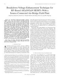
two very similar materials. <strong>The</strong> equilibrium phase of TiO2 at all temperature is known is<br />
Rutile and exhibits a tetragonal crystal structure as shown in Figure 6 with a = 4.4923 A<br />
and<br />
c = 2.8930 A [5]. Furthermore, the crystal is known to exhibit different electrical<br />
characteristics along these axes. For example, the dielectric constant along the a axis<br />
has been measured to be 89 whereas the along the c axis it has been measured to be<br />
173 [5]. TiO2-x is simply TiO2 that has had oxygen removed from this crystal, such that<br />
the new material has slightly less than two oxygen atoms per titanium atom [5].<br />
11
Figure 6: Crystal Structure of Rutile TiO2 (Source: [5])<br />
By measuring the Hall Effect coefficient, [5] was able to determine the electron carrier<br />
concentration in various samples of TiO2-x. <strong>The</strong>se experiments subsequently showed<br />
that excess electrons are generated as oxygen vacancies are introduced [5].<br />
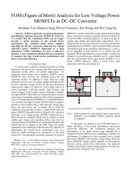
Figure 7 shows the carrier concentration ( ) as an inverse function of temperature (1/T)<br />
for various samples of TiO2-x. Oxygen was removed by reduction; the samples were<br />
heated to very high temperatures (600K to 900K) in an H 2 atmosphere and<br />
subsequently left to cool before measuring carrier concentrations. Higher reduction<br />
temperatures create TiO2-x samples with less oxygen and thus larger values of x [5].<br />
Figure 7 shows that as oxygen is removed (and x increased), the electron carrier<br />
concentration increases. This effect is most visible for the ceramic samples.<br />
Furthermore, the experiments indicated that majority carriers are in fact electrons [5].<br />
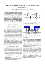
Additionally, the resistivity was measured by [5] and is shown below in Figure 8. <strong>The</strong>se<br />
results show that as the reduction temperature is increased (and x increased) the<br />
resistivity of ceramic TiO2 becomes smaller. From the [5] results, it is quite clear that as<br />
TiO2 is doped with oxygen vacancies it begins to behave as an n-type semiconductor<br />
[5].<br />
12
Figure 7: Majority Carrier Concentration in Reduced TiO2 samples (Source: [5])<br />
Figure 8: Resistivity in Ceramic ReducedTiO2 Samples (Source: [5])<br />
13
This n-type behaviour is believed to occur because the oxygen vacancies behave as<br />
donor centers. <strong>The</strong> vacancies thus raise the Fermi Energy and add electrons to the<br />
conduction band [5]. Attempting to quantify their results, [5] found that Equation (17)<br />
could be used to represent all of the carrier concentration curves. This equation uses<br />
four parameters: .<br />
(17)<br />
When the values for these parameters are selected for a given curve, a pattern<br />
emerges: and [5].This result suggests that there are two types of<br />
donor centers present, one with very low activation energy and one with a much larger<br />
activation energy [5]. As oxygen vacancies provide two donor electrons, there must two<br />
distinct energies associated with ionizing an electron into the conduction band [5]. Thus,<br />
this result is viewed as a confirmation that oxygen vacancies are behaving as electron<br />
donors.<br />
Anion Migration in Titanium Dioxide<br />
Another characteristic of TiO2 leveraged by the <strong>Memristor</strong> is an effect known as resistive<br />
switching. Resistive switching is the tendency for certain materials to exhibit a<br />
resistance that can be changed electrically and thus switched from one value to<br />
another. Generally, resistive switching takes on two possible forms: unipolar switching<br />
and bipolar switching [8]. In both cases, the resistance of the material changes when<br />
certain transition voltages are reached. For unipolar switching, the polarities of the “on”<br />
and “off” transition voltages are identical [8]. If a positive voltage turns on the device, a<br />
positive voltage is required to turn it off. For bipolar switching, once a certain state has<br />
14
een achieved, the polarity of the device must be reversed in order to switch the device<br />
[8]. Examples of both unipolar and bipolar switching are shown in Figure 9 with time<br />
indicated by the arrows.<br />
Figure 9: IV Curves for Unipolar (left) and Bipolar (right) Switching (Source: [8])<br />
It should be quite obvious that the IV curve for bipolar switching closely resembles the<br />
bowtie diagrams predicted by Chua for the <strong>Memristor</strong>. Indeed, the material used for the<br />
HP <strong>Memristor</strong> is TiO2, a material that exhibits bipolar resistive switching.<br />
<strong>The</strong> exact cause of resistive switching is still not completely understood and is in fact<br />
believed to be caused by different mechanisms for different materials [8]. For the case<br />
of TiO2, the mechanism of anion migration is suspected to be the cause of resistive<br />
switching [8]. Anion migration occurs when charged anions within the material begin to<br />
drift in the presence of an electric field [8]. For TiO2, the anions that are drifting are the<br />
positively charged oxygen vacancies.<br />
A description of TiO2 during anion migration is shown in Figure 10. <strong>The</strong> process begins<br />
when an electric field is applied and oxygen vacancies are formed at the anode. Oxygen<br />
15
vacancy generation is governed by the reaction described by equation (18) [8]. In this<br />
reaction, bonded oxygen (O o ) turns into oxygen gas molecules that escape into the<br />
anode while leaving behind positively charged oxygen vacancies ( ) in the crystal<br />
structure [8]. <strong>The</strong>se vacancies then drift across the material towards the cathode as a<br />
result of the applied electric field. Assuming that the cathode blocks ion exchange<br />
reactions, the oxygen vacancies will begin to accumulate near the cathode [8]. <strong>The</strong><br />
oxygen vacancies will then trap electrons emitted by the cathode, obeying equation (19)<br />
[8]. This reaction forms TiO2-x at the cathode (where n = x - 2), which exhibits a much<br />
lower resistance than TiO2. As the TiO2-x has a low resistance, its accumulation<br />
effectively moves the cathode to the right, forming a virtual cathode as indicated in<br />
Figure 10 [8].<br />
(18) ( )<br />
(19)<br />
V<br />
- +<br />
Cathode<br />
TiO2-x<br />
TiO2<br />
Anode<br />
n2e -<br />
ne - nV - o n(½)O 2<br />
Virtual Cathode<br />
Figure 10: Anion Migration in Titanium Dioxide with an Applied Electric Field<br />
16
As shown in Figure 10 and equation (18), oxygen vacancies are created at the anode<br />
when oxygen gas molecules are absorbed by the anode itself. Thus, the anode must be<br />
constructed of a material that exhibits fairly high oxygen mobility but will not react easily<br />
with oxygen [8]. Furthermore, a cathode material is required that does not absorb<br />
oxygen vacancies, allowing them to “pile up” at the cathode [8]. It is for these reasons<br />
that Platinum is often selected for both the anode and cathode in a <strong>Memristor</strong>. Selecting<br />
the same material for the anode and the cathode is important as it is a requirement for<br />
bipolar switching that the structure be symmetric [8].<br />
An interesting characteristic of anion migration in TiO2 is the formation of conducting<br />
filaments. Essentially, the process described above does not happen evenly across the<br />
material but instead tends to occur in narrow channels of TiO2-x [8]. Using a conductivetip<br />
atomic force microscope (C-AFM), these filaments can be observed by scanning the<br />
surface of titanium dioxide. Such a measurement is shown in Figure 11; on the left, the<br />
material was scanned during a low resistance state, on the right the same material was<br />
scanned during a high resistance state. <strong>The</strong> white spots correspond to the low resistivity<br />
filaments, there being significantly more of them during the low impedance state.<br />
Figure 11: Surface Resistivity of TiO 2 Measured Using a C-AFM (Source: [9])<br />
17
Applications of the <strong>Memristor</strong><br />
<strong>The</strong> <strong>Memristor</strong> has the potential to augment or enhance several areas of integrated<br />
circuit design and computing. Extensive literature regarding applications of the<br />
<strong>Memristor</strong> has been produced since the HP announcement but a few developments are<br />
particularly noteworthy.<br />
One highly pervasive area where <strong>Memristor</strong>s may be applied is that of non-volatile<br />
digital memory [10]. <strong>The</strong> <strong>Memristor</strong> is seen as having significant potential in this area as<br />
the device exhibits memory, does not require continuous power draw and consumes<br />
little physical area.<br />
row[0]<br />
column[0]<br />
column[1]<br />
column[2]<br />
row[1]<br />
row[2]<br />
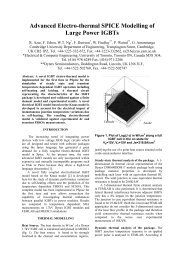
Figure 12: Example of a <strong>Memristor</strong> Crossbar Memory Topology<br />
For digital memory applications, one bit of information can be stored using a single<br />
<strong>Memristor</strong>. This can be achieved by forcing the <strong>Memristor</strong> to its extreme resistance<br />
values (R ON and R OFF ), each state corresponding to either a 1 or a 0. DC voltages are<br />
18
used to set the resistance of a <strong>Memristor</strong> element [10]. In order to read stored data, AC<br />
signals are utilized so that the stored data is not disturbed [10]. A crossbar arrangement<br />
is often used for this memory architecture, as shown in Figure 12 [10]. <strong>The</strong> crossbar<br />
topology is composed of a grid of horizontal and vertical traces. At each intersection, a<br />
vertical trace is connected to a horizontal trace by a <strong>Memristor</strong>. Thus, an individual<br />
<strong>Memristor</strong> can be programmed or read by applying a voltage to the necessary<br />
horizontal and vertical traces while letting the remaining traces float.<br />
Figure 13: Programmable Gain Differential Amplifier (Source: [3])<br />
While the <strong>Memristor</strong> can be used at its extreme resistance values in order to provide<br />
digital memory, it can also be made to behave in an analog manner. One potential<br />
application of this behaviour is that of a dynamically adjustable electric load [3]. Thus,<br />
existing electronic circuit topologies with characteristics that depend on a resistance can<br />
be made with <strong>Memristor</strong>s that behave as variable, programmable resistances. This<br />
19
design approach has the potential to create electronically adjustable filters and<br />
amplifiers as shown in Figure 13.<br />
A common operation involved in image recognition and other image processing<br />
techniques is that of edge detection. Edge detection identifies where large changes in a<br />
digital image occur, such as the outline of an object. However, edge detection is<br />
notoriously computationally intensive. One application of <strong>Memristor</strong>s identified by [10] is<br />
that of performing edge detection using a memristance grid. An example of this<br />
operation can be seen below in Figure 14. <strong>The</strong> light intensity of the original photo is<br />
applied as voltages to points on a grid of <strong>Memristor</strong>s (a). <strong>The</strong> resulting changes in<br />
resistance across the grid over time are then shown in the frames in (b). Thus, after the<br />
system has been allowed to settle, the edge detected image can be recovered by<br />
measuring the resistance of each element in the grid [10].<br />
Figure 14: <strong>Memristor</strong> Based Edge Detection (Source: [10])<br />
20
Report Summary<br />
<strong>The</strong> mathematical properties of a fourth fundamental passive circuit element were<br />
predicted 40 years ago by Leon Chua. This new circuit element was predicted to<br />
behave as a resistor but with a resistance that changed with the electric charge that had<br />
passed through the device. Dubbed the <strong>Memristor</strong>, it was not until 2008 that such a<br />
device was discovered by a team working at HP labs. <strong>The</strong> HP <strong>Memristor</strong> is a simple<br />
device constructed of a TiO2 thin film sandwiched between platinum electrodes. <strong>The</strong> HP<br />
<strong>Memristor</strong> is easy to manufacture but requires a modern nanometre scale process.<br />
<strong>The</strong> HP <strong>Memristor</strong> relies on two physical characteristics of titanium dioxide. <strong>The</strong> first<br />
characteristic is the sensitivity of TiO2 conductivity to oxygen depletion. TiO2 is normally<br />
an insulator but behaves as an n-type semiconductor when oxygen vacancies are<br />
introduced, forming TiO2-x. <strong>The</strong> second characteristic that the HP <strong>Memristor</strong> relies on is<br />
that of anionic migration, the tendency for oxygen vacancies within TiO2 to drift with an<br />
applied electric field.<br />
<strong>The</strong> <strong>Memristor</strong> has the potential for several important applications in the electronics and<br />
computing industries. <strong>The</strong>se applications include but are not limited to: non-volatile<br />
memory, analog electronics and image processing. <strong>The</strong>se applications take advantage<br />
of the <strong>Memristor</strong>s ability to store digital and analog information in a simple and power<br />
efficient manner.<br />
21
References<br />
[1] Chua, L.; , "<strong>Memristor</strong>-<strong>The</strong> missing circuit element," Circuit <strong>The</strong>ory, IEEE<br />
Transactions on , vol.18, no.5, pp. 507- 519, Sep 1971<br />
[2] Albo-Canals, Jordi; Pazienza, Giovanni E.; , "How to teach memristors in EE<br />
undergraduate courses," Circuits and Systems (ISCAS), 2011 IEEE International<br />
Symposium on , vol., no., pp.345-348, 15-18 May 2011<br />
[3] Sangho Shin; Kyungmin Kim; Sung-Mo Kang; , "<strong>Memristor</strong> Applications for<br />
Programmable Analog ICs," Nanotechnology, IEEE Transactions on , vol.10, no.2,<br />
pp.266-274, March 2011<br />
[4] Williams, R.; , "How We Found <strong>The</strong> Missing <strong>Memristor</strong>," Spectrum, IEEE , vol.45,<br />
no.12, pp.28-35, Dec. 2008<br />
[5] Breckenridge, Robert G.; and Hosler, William R.; , " Electrical Properties of<br />
Titanium Dioxide Semiconductors," American Physical Society , vol. 91, pp.793-802,<br />
Aug. 1953<br />
[6] D. Strukov, G. Snider, D. Stewart, and R. Williams, "<strong>The</strong> missing memristor<br />
found," Nature, vol. 453, no. 7191, pp. 80-83, 2008.<br />
[7] Kavehei, O.; Yeong-Seuk Kim; Iqbal, A.; Eshraghian, K.; Al-Sarawi, S.F.; Abbott,<br />
D.; , "<strong>The</strong> fourth element: Insights into the memristor," Communications, Circuits and<br />
Systems, 2009. ICCCAS 2009. International Conference on , vol., no., pp.921-927, 23-<br />
25 July 2009<br />
[8] R. Waser and M. Aono, “Nanoionics-based resistive switching memories,” Nat.<br />
Mater., vol. 6, no. 11, pp. 833–840, 2007.<br />
[9] Choi, B. J.; Jeong, D. S.; Kim, S. K.; Rohde, C.; Choi, S.; Oh, J. H.; Kim, H. J.;<br />
Hwang, C. S.; Szot, K.; Waser, R.; Reichenberg, B.; Tiedke, S.; , "Resistive switching<br />
mechanism of TiO 2 thin films grown by atomic-layer deposition," Journal of Applied<br />
Physics , vol.98, no.3, pp.033715-033715-10, Aug 2005<br />
[10] Prodromakis, T.; Toumazou, C.; , "A review on memristive devices and<br />
applications," Electronics, Circuits, and Systems (ICECS), 2010 17th IEEE International<br />
Conference on , vol., no., pp.934-937, 12-15 Dec. 2010<br />
22