ZR1 Install P3 5-07 - Subaru Technical Information System
ZR1 Install P3 5-07 - Subaru Technical Information System
ZR1 Install P3 5-07 - Subaru Technical Information System

You also want an ePaper? Increase the reach of your titles
YUMPU automatically turns print PDFs into web optimized ePapers that Google loves.
This vehicle is equipped with a remote controlled engine starter.<br />
To reduce the risk of serious Injury or death, switch engine starter<br />
system into service mode and disconnect the vehicle battery<br />
before performing any service on the vehicle.<br />
Ce véhicule est dotéd'un démarreur à distance. Pour réduire les<br />
risques de blessures graves ou mortelles, mettre le démarreur à<br />
distance en mode service et débrancher la batterie du véhicule<br />
avant d'effectuer des travaux d'entretien sur celui-ci.<br />
INSTALLATION<br />
INSTRUCTIONS<br />
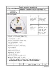
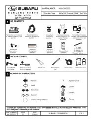
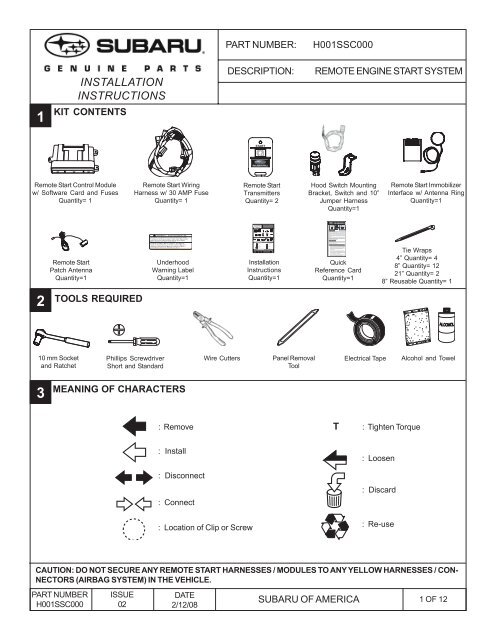
1 KIT CONTENTS<br />
Remote Start Control Module Remote Start Wiring<br />
Remote Start<br />
w/ Software Card and Fuses Harness w/ 30 AMP Fuse Transmitters<br />
Quantity= 1<br />
Quantity= 1<br />
Quantity= 2<br />
Vehic le Remote Star t <strong>System</strong><br />
<strong>Install</strong>ation<br />
Instructions<br />
WARNING: / AVERTISSEMENT<br />
This vehicle is equipped with a remote controlled engine starter.<br />
To reduce the risk of serious Injury or death, switch engine starter<br />
system into service mode and disconnect the vehicle battery<br />
before performing any service on the vehicle.<br />
Ce véhicule est dotéd'un démarreur à distance. Pour réduire les<br />
risques de blessures graves ou mortelles, mettre le démarreur à<br />
distance en mode service et débrancher la batterie du véhicule<br />
avant d'effectuer des travaux d'entretien sur celui-ci.<br />
Featuring P owerCode Technology<br />
TM For the Ultimate in Comfort, Convenience and Security<br />
Remote Start<br />
Underhood<br />
Patch Antenna<br />
Warning Label<br />
Quantity=1<br />
Quantity=1<br />
2 TOOLS REQUIRED<br />
10 mm Socket Phillips Screwdriver Wire Cutters<br />
and Ratchet Short and Standard<br />
3 MEANING OF CHARACTERS<br />
: Remove<br />
: <strong>Install</strong><br />
: Disconnect<br />
: Connect<br />
: Location of Clip or Screw<br />
PART NUMBER: H001SXA000<br />
DESCRIPTION: REMOTE ENGINE START SYSTEM<br />
<strong>Install</strong>ation<br />
Instructions<br />
Quantity=1<br />
Panel Removal<br />
Tool<br />
Remote Start Immobilizer<br />
Interface w/ Antenna Ring<br />
Quantity=1<br />
Tie Wraps<br />
4” Quantity= 4<br />
8” Quantity= 12<br />
21” Quantity= 2<br />
Electrical Tape Alcohol and Towel<br />
T : Tighten Torque<br />
: Loosen<br />
: Discard<br />
: Re-use<br />
CAUTION: DO NOT SECURE ANY REMOTE START HARNESSES / MODULES TO ANY<br />
YELLOW HARNESSES / CONNECTORS (AIRBAG SYSTEM) IN THE VEHICLE.<br />
PART NUMBER ISSUE DATE<br />
SUBARU OF AMERICA<br />
1 OF 10<br />
H001SXA000<br />
01 03/14/06<br />
®<br />
TM<br />
Hood Switch Mounting<br />
Bracket, Switch and 10”<br />
Jumper Harness<br />
Quantity=1<br />
REMOTE START QUICK REFERENCE<br />
Press 2 Times<br />
Press For 2 Seconds<br />
Remote Start<br />
Remote Start<br />
Activation<br />
Shutdown<br />
Starting Your Vehicle<br />
The remote control start function is activated by pressing<br />
the START (key icon) button twice within 3 seconds on<br />
your remote control transmitter. The system will check<br />
certain pre-conditions before starting, and if all safety<br />
parameters are correct, the engine will start within 5<br />
seconds. If the vehicle’s starter cranks but does not start<br />
or starts and stalls, the remote engine start system will<br />
power off then attempt to start the vehicle an additional<br />
four times.<br />
WARNING: TO AVOID DANGER OF CARBON MONOXIDE,<br />
NEVER REMOTE START A VEHICLE IN A CLOSED SPACE<br />
SUCH AS A CLOSED GARAGE.<br />
Turning Your Vehicle Off<br />
Press and hold the START (key icon) button again to turn<br />
the vehicle off. If the vehicle is left running the remote start<br />
system will allow the vehicle to run for a total of 15 minutes<br />
and then automatically turn off.<br />
Entering the Vehicle While it is Running via Remote Start<br />
1. Unlock the vehicle doors using the factory keyless<br />
remote. If the vehicle’s doors are unlocked manually<br />
using the key, the vehicle’s security system will trigger<br />
and the remote start system will turn off. Inserting<br />
the ignition key into the ignition cylinder and<br />
turning it to the ON or RUN position will disarm the<br />
security system.<br />
2. Enter the vehicle. Do not press the brake pedal.<br />
3. Insert the key into the ignition and turn to the ON positiion.<br />
If the ignition key is accidently turned to the start<br />
position, the system’s “starter anti-grind” feature will<br />
prevent the starter from re-cranking.<br />
4. Press the brake pedal. The remote starter disengages,<br />
the vehicle’s power window features are re-enabled<br />
and the vehicle will operate normally.<br />
Quick<br />
Reference Card<br />
Quantity=1<br />
REMOTE START QUICK REFERENCE<br />
Press 2 Times<br />
Press For 2 Seconds<br />
Remote Start<br />
Remote Start<br />
Activation<br />
Shutdown<br />
Starting Your Vehicle<br />
The remote control start function is activated by pressing<br />
the START (key icon) button twice within 3 seconds on<br />
your remote control transmitter. The system will check<br />
certain pre-conditions before starting, and if all safety<br />
parameters are correct, the engine will start within 5<br />
seconds. If the vehicles starter cranks but does not start<br />
or starts and stalls, the remote engine start system will<br />
power off then attempt to start the vehicle an additional<br />
four times.<br />
WARNING: TO AVOID DANGER OF CARBON MONOXIDE,<br />
NEVER REMOTE START A VEHICLE IN A CLOSED SPACE<br />
SUCH AS A CLOSED GARAGE.<br />
Turning Your Vehicle Off<br />
Press and hold the START (key icon) button again to turn<br />
the vehicle off. If the vehicle is left running the remote start<br />
system will allow the vehicle to run for a total of 15 minutes<br />
and then automatically turn off.<br />
Entering the Vehicle While it is Running via Remote Start<br />
1. Unlock the vehicle doors using the factory keyless<br />
remote. If the vehicles doors are unlocked manually<br />
using the key, the vehicles security system will trigger<br />
and the remote start system will turn off. Inserting<br />
the ignition key into the ignition cylinder and<br />
turning it to the ON or RUN position will disarm the<br />
security system.<br />
2. Enter the vehicle. Do not press the brake pedal.<br />
3. Insert the key into the ignition and turn to the ON positiion.<br />
If the ignition key is accidently turned to the start<br />
position, the systems starter anti-grind feature will<br />
prevent the starter from re-cranking.<br />
4. Press the brake pedal. The remote starter disengages,<br />
the vehicles power window features are re-enabled<br />
and the vehicle will operate normally.<br />
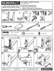
PART NUMBER:<br />
H001SSC000<br />
INSTALLATION<br />
INSTRUCTIONS<br />
DESCRIPTION:<br />
REMOTE ENGINE START SYSTEM<br />
1<br />
KIT CONTENTS<br />
START<br />
Remote Start Control Module<br />
w/ Software Card and Fuses<br />
Quantity= 1<br />
Remote Start Wiring<br />
Harness w/ 30 AMP Fuse<br />
Quantity= 1<br />
Remote Start<br />
Transmitters<br />
Quantity= 2<br />
Hood Switch Mounting<br />
Bracket, Switch and 10”<br />
Jumper Harness<br />
Quantity=1<br />
Remote Start Immobilizer<br />
Interface w/ Antenna Ring<br />
Quantity=1<br />
Remote Start<br />
Patch Antenna<br />
Quantity=1<br />
WARNING: / AVERTISSEMENT<br />
Underhood<br />
Warning Label<br />
Quantity=1<br />
<strong>Install</strong>ation<br />
Instructions<br />
Quantity=1<br />
Quick<br />
Reference Card<br />
Quantity=1<br />
Tie Wraps<br />
4” Quantity= 4<br />
8” Quantity= 12<br />
21” Quantity= 2<br />
8” Reusable Quantity= 1<br />
2<br />
TOOLS REQUIRED<br />
10 mm Socket<br />
and Ratchet<br />
Phillips Screwdriver<br />
Short and Standard<br />
Wire Cutters<br />
Panel Removal<br />
Tool<br />
Electrical Tape<br />
Alcohol and Towel<br />
3<br />
MEANING OF CHARACTERS<br />
: Remove T : Tighten Torque<br />
: <strong>Install</strong><br />
: Disconnect<br />
: Connect<br />
: Location of Clip or Screw<br />
: Loosen<br />
: Discard<br />
: Re-use<br />
CAUTION: DO NOT SECURE ANY REMOTE START HARNESSES / MODULES TO ANY YELLOW HARNESSES / CON-<br />
NECTORS (AIRBAG SYSTEM) IN THE VEHICLE.<br />
PART NUMBER<br />
H001SSC000<br />
ISSUE<br />
02<br />
DATE<br />
2/12/08<br />
SUBARU OF AMERICA<br />
1 OF 12
4 VEHICLE PREPARATION<br />
1. Using a 10 mm socket/ratchet, disconnect the negative battery<br />
terminal.<br />
2. Using a phillips screwdriver, remove one (1) phillips screw on the<br />
underside of the steering column shroud and carefully unsnap<br />
and remove the lower panel. Be careful not to damage the lower<br />
dashboard panel. (FIGURE A)<br />
3. Using a panel removal tool, carefully remove the left side dashboard<br />
panel (FIGURE B). Remove 2 screws securing the lower<br />
dashboard panel on the left side of the dashboard. (FIGURE C)<br />
FIGURE A<br />
4. Using a panel removal tool, carefully remove the driver’s side<br />
lower dashboard panel and unplug any connectors. (FIGURE D)<br />
5. Remove the metal knee bolster by removing the two (2) 10mm<br />
bolts. (FIGURE E)<br />
FIGURE B<br />
FIGURE C<br />
FIGURE D<br />
FIGURE E<br />
PART NUMBER<br />
H001SSC000<br />
ISSUE<br />
02<br />
DATE<br />
2/12/08<br />
SUBARU OF AMERICA<br />
2 OF 12
5<br />
WINDSHIELD MOUNT ANTENNA INSTALLATION<br />
1. Locate the position at the top of the windshield 1” left of center<br />
and 1” from the top of the headliner. (FIGURE F)<br />
2. Using alcohol, clean the area thoroughly.<br />
3. Remove the adhesive backing on the antenna assembly and<br />
apply the antenna to the windshield in the area indicated above.<br />
(FIGURE F)<br />
FIGURE F<br />
4. Carefully pry the A-pillar trim panel away from the windshield<br />
while gently tucking the antenna cable behind the A-pillar trim<br />
panel starting at the headliner and finishing at the dashboard.<br />
Use caution not to damage the A-pillar trim panel. (FIGURE G)<br />
5. Route the antenna cable to the opening on the left side of the<br />
driver’s dashboard. The antenna cable will be plugged into the<br />
remote start control module later.<br />
FIGURE G<br />
PART NUMBER<br />
H001SSC000<br />
ISSUE<br />
02<br />
DATE<br />
2/12/08<br />
SUBARU OF AMERICA<br />
3 OF 12
6<br />
MAIN HARNESS CONNECTIONS<br />
6-WAY IGNITION SWITCH CONNECTIONS<br />
1. Locate the 6-pin ignition switch connector on the left side of the steering<br />
column and unplug. (FIGURE H)<br />
2. Release the black tab that secures the factory ignition harness to the metal<br />
steering column frame. (FIGURE H)<br />
3. Plug the previously unplugged vehicle’s female ignition switch connector into<br />
the remote start harness 6-pin male ignition connector. (FIGURE I)<br />
FIGURE H<br />
4. Plug the remote start harness 6-pin female connector into the vehicle’s ignition<br />
switch (FIGURE J). Make sure that the wires exiting the 6-pin female ignition<br />
connector are bent towards the front of the vehicle to allow for enough clearance<br />
when re-assembling the lower steering column shroud. (FIGURE K)<br />
5. Using the supplied 8” reusable tie wrap, secure the mated remote start<br />
harness 6-pin male and vehicle’s 6-pin female connectors to the bottom of<br />
the metal bracket where the vehicle’s ignition harness was previously secured<br />
(refer to step 2 above). When securing the mated connectors to the bottom<br />
of the metal bracket, make sure the connectors are in-line with the metal<br />
bracket. This will ensure for proper re-assembly of the lower steering column<br />
shroud. (FIGURE J)<br />
FIGURE I<br />
6. Using one (1) of the supplied 8” tie wraps, secure the vehicle’s ignition harness<br />
to the multifunction switch frame, this will prevent rattling of the factory ignition<br />
harness and allow for proper re-assembly of the lower steering column shroud.<br />
(FIGURE J). NOTE: Temporarily leave the tie wrap loose to allow for securing<br />
of the immobilizer interface antenna harness later in the instruction manual.<br />
FIGURE J<br />
7. Route the remote start harness down the left side of the steering column<br />
towards the front of the vehicle.<br />
FIGURE K<br />
PART NUMBER<br />
H001SSC000<br />
ISSUE<br />
02<br />
DATE<br />
2/12/08<br />
SUBARU OF AMERICA<br />
4 OF 12
6<br />
MAIN HARNESS CONNECTIONS (continued)<br />
24-PIN & 2-PIN PRE-FIT CONNECTIONS ABOVE & BEHIND FUSE PANEL<br />
1. Locate the vehicle’s 24-pin and 2-pin pre-fit connections located behind<br />
the fuse panel to the left of the steering column. These connectors<br />
are secured to the vehicle wiring using breakaway tape. (FIGURE L)<br />
2. When the 2-pin pre-fit connector is located, unplug and discard the<br />
mating wire jumper.<br />
FIGURE L<br />
Pre-fit<br />
Connectors<br />
3. Carefully route the remote start harness 24-pin and 2-pin connectors<br />
behind the fuse panel, making sure that they will not interfere with any<br />
vehicle moving components and re-assembly of dashboard panels.<br />
4. Plug the remote start harness 24-pin and 2-pin male connectors into<br />
the corresponding 24-pin and 2-pin vehicle female connectors.<br />
(FIGURE M)<br />
5. Using one (1) of the supplied 8” tie wraps, secure the remote start<br />
wiring to existing vehicle wiring. (FIGURE N)<br />
FIGURE M<br />
6. Route the remote start harness programming button and 30-AMP fuse<br />
assembly to the left side of the vehicle’s fuse panel assembly from<br />
behind and secure the wiring to the left side of the fuse panel using<br />
one (1) of the supplied 8” tie wraps (FIGURE O). DO NOT SECURE<br />
THE REMOTE START HARNESS TO ANY VEHICLE YELLOW<br />
HARNESSES / CONNECTORS (AIRBAG SYSTEM).<br />
FIGURE N<br />
FIGURE O<br />
PART NUMBER<br />
H001SSC000<br />
ISSUE<br />
02<br />
DATE<br />
2/12/08<br />
SUBARU OF AMERICA<br />
5 OF 12
7<br />
CONTROL MODULE CONNECTION & MOUNTING / IMMOBILIZER INTERFACE MOUNTING<br />
REMOTE ENGINE START CONTROL MODULE MOUNTING<br />
1. Locate the vehicle’s Body Integrated Unit (BIU) mounted to the right<br />
side of the steering column. (FIGURE P)<br />
Steering<br />
Column<br />
2. Route the previously installed antenna cable towards the remote start<br />
harness 24-pin, 16-pin and 10-pin connectors. Route the antenna<br />
cable and remote start harness 24-pin, 16-pin and 10-pin connectors<br />
below the steering column towards the BIU. Plug the 2-pin antenna<br />
cable connector into the 2-pin port on the back of the remote start<br />
control module and plug the 24 pin, 16 pin and 10 pin connectors into<br />
the remote start control module. (FIGURE Q)<br />
NOTE: The small 4-pin and 5-pin connectors on the control<br />
module are not used. (FIGURE R)<br />
Antenna<br />
FIGURE P<br />
BIU<br />
3. Secure the remote start control module to the right side of the BIU<br />
using the supplied velcro making sure the 3 connectors on the remote<br />
start control module are facing down. (FIGURE S)<br />
4. As a secondary mounting provision, secure the remote start control<br />
module to the BIU using one (1) of the supplied 21” tie wraps.<br />
(FIGURE S)<br />
16-Way 24-Way 10-Way<br />
FIGURE Q<br />
5. Using two (2) of the supplied 8” tie wraps, secure the remote start<br />
harness and antenna cable to the existing vehicle wiring above the<br />
diagnostic connector (pictured in gray) and the exsisting factory<br />
bracket (pictured in gray) under the steering column (FIGURE T).<br />
NOTE: Use care to make sure that the remote engine start<br />
harness does not rest against the side of the dashboard mounted<br />
fusebox or any sharp metal objects. If the vehicle is equipped<br />
with a telescopic steering column, be sure to fully exercise the<br />
telescopic feature to verify that the the harness does not bind<br />
or rub in any areas.<br />
The 4-pin and 5-pin ports on the face of the RES<br />
control module are not used. Plugging harnesses into<br />
these ports will cause damage to the RES control module<br />
FIGURE R<br />
Remote Engine<br />
Start Control<br />
Module<br />
Fuse Box<br />
FIGURE S<br />
FIGURE T<br />
PART NUMBER<br />
H001SSC000<br />
ISSUE<br />
02<br />
DATE<br />
2/12/08<br />
SUBARU OF AMERICA<br />
6 OF 12
7<br />
CONTROL MODULE CONNECTION & MOUNTING / IMMOBILIZER INTERFACE MOUNTING<br />
(continued)<br />
IMMOBILIZER INTERFACE MOUNTING<br />
1. Locate the A/T Control Module to the left of the brake pedal. Using alcohol,<br />
clean an area on the left side of the A/T Control Module. Using the supplied<br />
velcro and one (1) 21” tie wrap, secure the immobilizer interface to the A/T<br />
Control Module making sure that the immobilizer interface connectors are<br />
facing down towards the vehicle’s floor. (FIGURE U)<br />
2. Plug in the 4-pin immobilizer interface connector (in the remote start harness)<br />
into the 4-pin connector on the immobilizer interface. (FIGURE U)<br />
A/T Control<br />
Module<br />
FIGURE U<br />
8<br />
IMMOBILIZER INTERFACE ANTENNA RING MOUNTING<br />
1. Locate the two (2) phillips screws at the steering column that secure the<br />
upper steering column shroud to the steering column assembly. Refer<br />
to FIGURE V for location reference.<br />
2. Using a phillips screwdriver, loosen but do not remove the two (2) phillips<br />
screws. (FIGURE W)<br />
3. Locate the illuminated ignition cylinder ring and gently slip the immobilizer<br />
interface antenna ring behind the illuminated ring and behind the upper<br />
steering column shroud. Re-secure the previously loosened phillips screws<br />
securing the upper steering column shroud to the steering column<br />
assembly. (FIGURE X)<br />
FIGURE V<br />
4. Route the immobilizer interface antenna ring wiring down the left side of<br />
the steering column and plug into the 2-pin port on the immobilizer interface<br />
(refer back to FIGURE U). Secure the immobilizer interface antenna ring<br />
wiring to the existing vehicle wiring and remote start harness using four<br />
(4) of the supplied 4” tie wraps. Be sure to route wiring to avoid any<br />
steering column moving parts. A small amount of slack in the harness is<br />
required to accomodate movement of the tilt / telescopic steering wheel.<br />
FIGURE W<br />
FIGURE X<br />
PART NUMBER<br />
H001SSC000<br />
ISSUE<br />
02<br />
DATE<br />
2/12/08<br />
SUBARU OF AMERICA<br />
7 OF 12
This vehicle is equipped with a remote controlled engine starter.<br />
To reduce the risk of serious Injury or death, switch engine starter<br />
system into service mode and disconnect the vehicle battery<br />
before performing any service on the vehicle.<br />
Ce véhicule est doté d'un démarreur à distance. Pour réduire les<br />
risques de blessures graves ou mortelles, mettre le démarreur à<br />
distance en mode service et débrancher la batterie du véhicule<br />
avant d'effectuer des travaux d'entretien sur celui-ci.<br />
9<br />
HOOD SAFETY SWITCH MOUNTING<br />
1. In the engine compartment, locate the 2-pin pre-fit hood safety switch<br />
connector secured to the wire harness with breakaway tape between<br />
the power steering fluid reservoir tank and the air filter box on the<br />
passenger’s side of the vehicle (FIGURE Y). Remove the two (2)<br />
10mm bolts securing the power steering fluid reservoir tank and move<br />
the power steering reservoir tank slightly for easier access to the 2-pin<br />
pre-fit hood safety switch connector. (FIGURE Z)<br />
FIGURE Y<br />
2. Plug the supplied remote start harness 10” hood safety switch wiring<br />
harness to the vehicle’s 2-pin pre-fit connector.<br />
3. Re-install the 10mm bolt that secures the power steering reservoir<br />
tank to the side fenderwall (the second 10mm bolt will be re-installed<br />
later).<br />
4. Mount the hood safety switch bracket with the remaining 10mm bolt<br />
securing the power steering reservoir tank to the vehicle’s body, hold<br />
the bracket firmly when tightening. (FIGURE AA) NOTE: The hood<br />
safety switch bracket locating tab must slot into the groove on the<br />
power steering reservoir tank. (FIGURE BB) Torque the bolt to 10.8<br />
Nm +/- 2 Nm (1.10 Kgf-m +/- 0.2 Kgf-m, 8 ft-lbs +/- 1.5 ft-lbs).<br />
FIGURE Z<br />
5. Securely mount (snap-in) the supplied hood safety switch in the bracket<br />
and plug the 2-pin female connector of the remote start harness 10”<br />
hood safety switch wiring harness to the base of the hood safety switch.<br />
(FIGURE AA & BB)<br />
FIGURE AA<br />
FIGURE BB<br />
10<br />
UNDER HOOD WARNING LABEL MOUNTING<br />
1. Using alcohol clean the top of the air intake plenum.<br />
2. Remove the adhesive backing of the underhood warning<br />
label and secure to the top of the air intake plenum.<br />
(FIGURE CC)<br />
WARNING: / AVERTISSEMENT<br />
FIGURE CC<br />
PART NUMBER<br />
H001SSC000<br />
ISSUE<br />
02<br />
DATE<br />
2/12/08<br />
SUBARU OF AMERICA<br />
8 OF 12
11<br />
SYSTEM POWER-UP<br />
After all connections are complete, re-connect the vehicle’s negative battery terminal.<br />
NOTE: THE VEHICLE’S HORN MAY BEGIN TO HONK ON AND OFF. iF THIS OCCURS, PRESSING<br />
THE RKE TRANSMITTER UNLOCK BUTTON OR TURNING THE IGNITION KEY TO THE RUN<br />
POSITION WILL SILENCE THE HORN.<br />
12<br />
TACHOMETER IDLE SPEED PROGRAMMING<br />
NOTE: THE VEHICLE’S HOOD MUST BE CLOSED AND LATCHED THROUGHOUT<br />
THIS PROCESS<br />
1. Open driver’s door (leave open throughout programming operation).<br />
2. Turn the ignition key to the ON or RUN position.<br />
3. Press and hold the momentary programming button for approximately 10 seconds<br />
until the vehicle’s horn honks (3) times. (FIGURE DD)<br />
4. Release the momentary programming button.<br />
5. Press and release the momentary programming button (secured to a wiring harness<br />
in front of the vehicle’s dashboard mounted fuse box, FIGURE DD). The vehicle’s<br />
horn will honk (4) times.<br />
6. Press and release the vehicle’s brake pedal (1) time. The horn will honk (1) time<br />
to indicate that the system has entered tachometer idle speed programming<br />
FIGURE DD<br />
mode.<br />
7. Start the vehicle with the ignition key. The RES system will begin honking the vehicle’s horn 1 time every 3 seconds<br />
to indicate a valid tach signal.<br />
8. When the engine has settled to a normal idle speed (normally 750-1000 RPM), press and release the brake pedal<br />
(1) time. The horn will honk (2) times to indicate the system has exited tach idle speed programming. Be sure<br />
that the vehicle has maintained 750-1000 RPM idle speed prior to exiting tachometer idle speed<br />
programming.<br />
9. Turn the ignition key to the OFF position.<br />
13<br />
PANEL RE-ASSEMBLY<br />
1. Re-install the knee bolster and torque the 10mm bolts to 10.8 Nm +/- 2 Nm (1.10<br />
Kgf-m +/- 0.2 Kgf-m, 8 ft-lbs +/- 1.5 ft-lbs). (FIGURE EE)<br />
2. Reinstall the steering column shroud and secure in place with one (1) phillips<br />
screw.<br />
3. Plug in any previously removed connectors and re-install the lower dashboard<br />
panel (refer to FIGURE D).<br />
T<br />
FIGURE EE<br />
T<br />
4. Re-install the two (2) phillips screws on the left side of the dashboard that secure<br />
the lower dashboard panel in place. (refer to FIGURE C)<br />
5. Re-install the left side dashboard panel. (refer to FIGURE B)<br />
6. At the end of the installation, insert the Quick Reference Card into the Owner’s<br />
<strong>Information</strong> Kit.<br />
PART NUMBER<br />
H001SSC000<br />
ISSUE<br />
02<br />
DATE<br />
2/12/08<br />
SUBARU OF AMERICA<br />
9 OF 12
14<br />
IMMOBILIZER INTERFACE PROGRAMMING<br />
Most new <strong>Subaru</strong> vehicles are equipped with an immobilizer system that will act as an anti-theft device preventing<br />
the vehicle from starting if an incorrect ignition key is used to start the vehicle. Each vehicle ignition key is<br />
equipped with a transponder that will transmit an ID code each time the vehicle ignition is turned on with the<br />
ignition key. During the Select Monitor (SMIII) registration process, the transponder ID code is registered by the<br />
vehicle’s body integrated unit (BIU). For security reasons all available ignition keys are required to be registered<br />
any time a new key is added or replaced.<br />
During the remote start process there will be no ignition key present to transmit a proper ID code when the vehicle<br />
is started. To simulate an ignition key during the remote start process an immobilizer interface is used to transmit<br />
a registered ID code to the ignition switch through an antenna ring that is mounted around the vehicle’s ignition<br />
switch.<br />
During the registration process, the remote start immobilizer interface will be treated as an ignition key by the<br />
vehicle. To simulate turning the ignition to the RUN position we will use a combination of pressing the remote start<br />
momentary programming button (mounted to a harness in front of the vehicle’s dashboard fusebox) and activating<br />
the remote start system by pressing the START button on the remote start transmitter two (2) times.<br />
• Pressing the momentary programming button one (1) time will delay the remote start crank output for<br />
60 - seconds. This will prevent the starter from cranking while the SDI is attempting to program the<br />
immobilizer interface as an ignition key.<br />
• Activating the remote start system by pressing the remote start transmitter button two (2) times will both<br />
activate the immobilizer interface and power the ignition circuits. This combination will make the vehicle<br />
think that the ignition switch was turned to the RUN position using an actual ignition key.<br />
Under normal situations the immobilizer interface will be registered to the vehicle as the 4th key. In the event that<br />
all vehicle ignition keys are not present at time of registration, the immobilizer interface should be registered as the<br />
last key (example: 2 ignition keys are available, the immobilizer interface is registered as the third key).<br />
POINTS TO REMEMBER<br />
1. Prior to programming the immobilizer interface, the vehicle tach idle speed section of the installation manual<br />
must be completed first.<br />
2. The vehicle’s hood must remain closed and latched during the entire process.<br />
3. The vehicle’s battery must be fully charged.<br />
4. All ignition keys (3 keys are present with a new vehicle) must be present prior to programming. Any ignition<br />
key that is not registered during the immobilizer interface programming process will no longer start the<br />
vehicle.<br />
5. The immobilizer teaching operation code for all Forester vehicles will need to be entered at this time.<br />
6. The vehicle specific five (5) digit security ID will be required every time the registration process is completed.<br />
The vehicle security ID is located on the larger of the 2 vehicle key tags.<br />
7. Immobilizer interface programming / key registration will be completed using the “<strong>Subaru</strong> Diagnostic Interface”<br />
(SDI) operating in “Stand Alone Mode”. When operating in stand alone mode, the SDI does not need to<br />
be plugged into the computer<br />
PART NUMBER<br />
H001SSC000<br />
ISSUE<br />
02<br />
DATE<br />
2/12/08<br />
SUBARU OF AMERICA<br />
10 OF 12
14<br />
IMMOBILIZER INTERFACE PROGRAMMING, CONTINUED<br />
SDI SETUP<br />
Plug the SDI<br />
diagnostic plug<br />
into the vehicles<br />
diagnostic<br />
connector<br />
Insert any ignition<br />
key into the<br />
ignition cylinder<br />
and turn to the<br />
RUN position<br />
Press and hold the SDI<br />
“Menu” and “C” buttons<br />
simultaneously for<br />
approximately 5 seconds<br />
to enter stand alone mode<br />
Proceed to<br />
“Registration<br />
Setup”<br />
REGISTRATION SETUP<br />
Using the arrows<br />
on the SDI select<br />
“<strong>Subaru</strong> Vehicle”<br />
ENTER<br />
Using the arrows<br />
on the SDI select<br />
“Imm Regist”<br />
ENTER<br />
The SDI screen<br />
will display<br />
"Select Reg Sys"<br />
Press Enter to<br />
select Immobi Sys<br />
SDI screen will display<br />
"Smart <strong>System</strong> : ENT<br />
Otherwise : C"<br />
Select C<br />
SDI screen will display<br />
"Confirm IGN ON<br />
YES : ENT / NO : C "<br />
Press Enter<br />
SDI screen will display<br />
engine type<br />
Press ENTER<br />
to confirm<br />
SDI screen prompts for<br />
the 4-digit teaching<br />
operation code. Enter<br />
the code using the<br />
arrows on the SDI<br />
The SDI screen<br />
will display<br />
ENTER “Execute Key ENTER<br />
Reg?"<br />
SDI screen prompts for<br />
the 5-digit security ID<br />
(vehicle specific ). Enter<br />
the code using the<br />
arrows on the SDI<br />
SDI screen will<br />
ENTER display ENTER<br />
“Execute Key Reg"<br />
SDI screen will<br />
display<br />
“Registering Key<br />
Proceed to “2 nd Key<br />
Registration” or<br />
“Immobilizer Interface<br />
Registration” if no<br />
additional ignition keys<br />
are available<br />
2nd KEY REGISTRATION<br />
SDI screen will<br />
display “Key reg<br />
OK Reg 2nd key?"<br />
ENTER<br />
SDI screen will<br />
display “IG OFF Key<br />
Change”. Remove<br />
first key, insert 2 nd<br />
key and cycle to RUN<br />
SDI screen will<br />
display “Execute<br />
Key Reg?"<br />
ENTER<br />
SDI screen will<br />
display<br />
“Registering Key<br />
Proceed to “3 rd Key<br />
Registration” or<br />
“Immobilizer Interface<br />
Registration” if no<br />
additional ignition keys<br />
are available<br />
3rd KEY REGISTRATION<br />
SDI screen will<br />
display “Register<br />
3rd Key?”<br />
ENTER<br />
SDI screen will<br />
display “IG OFF Key<br />
Change”. Remove<br />
2nd key, insert 3rd<br />
key and cycle to RUN<br />
SDI screen will<br />
display “Execute<br />
Key Reg?"<br />
ENTER<br />
SDI screen will<br />
display<br />
“Registering Key<br />
Proceed to “Immobilizer<br />
Interface Registration”<br />
IMMOBILIZER INTERFACE REGISTRATION<br />
SDI screen will<br />
display “Register<br />
4th Key?”<br />
ENTER<br />
SDI screen will<br />
display “IG OFF Key<br />
Change”. Remove<br />
3 rd key<br />
Press and release the remote start<br />
momentary programming button<br />
(mounted with a tie wrap in front of<br />
the fuse panel one (1) time. There<br />
will be no response from the<br />
remote start system, SDI or<br />
vehicle. (FIGURE A)<br />
Press and release the START button one (1) time<br />
on each remote start transmitter consecutively<br />
within 5 seconds. The horn and parking lights<br />
will each flash every time the transmitter button<br />
is pressed<br />
REMOTE ENGINE START HARNESS<br />
MOMENTARY PROGRAMMING BUTTON<br />
START<br />
REMOTE ENGINE<br />
START TRANSMITTER<br />
START BUTTON<br />
The vehicle’s<br />
ignition and<br />
instrument panel<br />
will power<br />
SDI screen will<br />
display “Execute<br />
Key Reg?"<br />
ENTER<br />
SDI screen will<br />
display<br />
“Registering Key<br />
SDI screen will<br />
display “Ending<br />
Key Registration”<br />
IMPORTANT!<br />
Press the vehicle’s<br />
brake pedal one<br />
(1) time. The<br />
ignition will turn off<br />
Registration<br />
Complete<br />
PART NUMBER<br />
H001SSC000<br />
ISSUE<br />
02<br />
DATE<br />
2/12/08<br />
SUBARU OF AMERICA<br />
11 OF 12
15<br />
POST INSTALLATION CHECKLIST<br />
1. REMOTE ENGINE START- Make sure the key is removed from the ignition switch and the engine hood is<br />
closed. Press the START button twice within 3 seconds - The parking lights should flash twice, the horn should<br />
beep twice then the vehicle should crank and start. Once started the parking lights will turn on and stay on<br />
signifying the vehicle is started.<br />
2. RUNNING WITH IGNITION KEY - While the vehicle is running under remote engine start, confirm that all<br />
function’s (lock, unlock, etc.) operate properly on the FACTORY transmitter. Once FACTORY transmitter<br />
functionality is confirmed press the UNLOCK button on FACTORY transmitter and enter the vehicle, insert the<br />
ignition key and turn the ignition to the run position, press the brake pedal - At this time the vehicle should be<br />
running by the ignition key and the remote engine start was shut down when the brake pedal was pressed. Turn<br />
off the ignition switch and the vehicle should shut off.<br />
3. BRAKE PEDAL SAFETY - Restart the vehicle using the remote engine start, enter the vehicle, press the brake<br />
pedal - The vehicle should shut off.<br />
4. KEY-IN-SENSE - Insert the ignition key into the ignition switch but keep in off position, activate the remote<br />
engine start function - the vehicle should flash the lights as if it is going to start but then the horn should beep<br />
twice and the remote engine starter does not attempt to start the vehicle since it senses the key in the ignition.<br />
5. HOOD SAFETY SWITCH - Open the engine hood and activate the remote engine start function - The horn<br />
should beep two additional times signifying that hood safety switch is tripped and the vehicle will not start.<br />
6. HEATER / AC FUNCTION - Insert the ignition key and turn the ignition to the run position, preset the vehicle’s<br />
heater or air conditioning to the on position then turn the ignition off and remove the ignition key. Activate the<br />
remote engine start system and verify that the heater or air conditioning turns on to the preset setting.<br />
7. 15-MINUTE RUN TIME - Activate the remote engine start system and allow the system to run for the 15-minute<br />
preset run time. The remote engine start system should shut the vehicle off in 15 minutes (+/- 10 seconds).<br />
8. SECURITY DISARM VERIFICATION - Activate the remote engine starter. After the vehicle has started, manually<br />
unlock the vehicle’s doors using the ignition key and open any door. The horn should begin a steady honk and<br />
the engine will shut down. Press the UNLOCK button on the FACTORY transmitter and verify that the horn<br />
stops honking (the vehicle will not automatically restart).<br />
9. TRANSMITTER FUNCTIONALITY VERIFICATION - Activate the remote engine starter using both of the supplied<br />
single button transmitters.<br />
FUNCTIONAL TESTING IS NOW COMPLETE.<br />
PART NUMBER<br />
H001SSC000<br />
ISSUE<br />
02<br />
DATE<br />
2/12/08<br />
SUBARU OF AMERICA<br />
12 OF 12<br />
1032365B