Phoenix Edge User Guide - Castle Creations
Phoenix Edge User Guide - Castle Creations
Phoenix Edge User Guide - Castle Creations
- No tags were found...

Create successful ePaper yourself
Turn your PDF publications into a flip-book with our unique Google optimized e-Paper software.
Safety First!<br />
For use by adults only.<br />
An electric motor that is connected to a battery and speed control may start<br />
unexpectedly and could cause serious injuries.<br />
Always treat a powered system with respect.<br />
Always remove the propeller or disengage the pinion gear when you are working on a<br />
plane or helicopter with the battery connected.<br />
<br />
Please observe all local laws regarding the flying of remote control aircraft or other<br />
control of remote control vehicles<br />
Never fly over others or near crowds.<br />
Never fly a controller that has been involved in a serious crash. Send it back to <strong>Castle</strong> for<br />
inspection as there may be damage that is not visible to the untrained eye.<br />
<strong>Castle</strong> <strong>Creations</strong> is not responsible for your use of this product, or any damage or<br />
injuries you may cause or sustain as a result of its usage.<br />
www.castlecreations.com/edge<br />
<br />
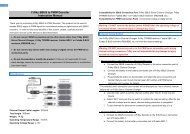
INSTALLING YOUR EDGE ESC<br />
1. Add your battery connector<br />
You must attach a quality battery connector of your choice to the red (+) and black (-) power wires. Solder the battery<br />
connector to the wires. ENSURE THAT THE POLARITY IS CORRECT (red wire to battery red wire, black wire to battery black<br />
wire). Follow the instructions provided with the battery connector.<br />
2. Connect the motor to your ESC<br />
Solder the corresponding connectors for your motor to the wires coming from the ESC, or solder the motor wires directly to<br />
the motor leads on the ESC.<br />
Always use electronics grade solder and make sure your solder joint is solid. Poor soldering is a common cause of in-flight<br />
failure! Ensure connectors are properly protected with insulation or heat-shrink to prevent shorts.<br />
3. Connect the ESC to your receiver<br />
Connect the receiver lead (the brown/red/orange wires with a black plastic connector on the end) to the throttle channel on<br />
your receiver.<br />
If you choose to use the white AUX Line, discussed later, please connect it as needed.<br />
4. BEC operation.<br />
The <strong>Edge</strong> and <strong>Edge</strong> LITE controllers have an onboard BEC circuit that provides power for the RX and servos. This BEC is<br />
capable of supplying up to 5 amps of power. If the servos in the system draw more current, even briefly, please use an<br />
outboard power source. <strong>Castle</strong>’s CC BEC PRO is highly recommended.<br />
If an external power source is used, the red wire on the <strong>Edge</strong> throttle cable must be disconnected from the wiring harness.<br />
We recommend lifting the plastic retaining tab and sliding the small connector out of the housing. Cover this connector with<br />
tape or shrink wrap.<br />
© 2013 <strong>Castle</strong> <strong>Creations</strong>, Inc. P/N: 095-0176-00 Revisi on Date - 03/2013 PAGE 1 of 6
NOTE TO USERS WITH A FUTABA TRANSMITTER: You must reverse the throttle channel signal on your transmitter. Please<br />
refer to your Futaba instructions.<br />
5. Reversing rotation (if necessary)<br />
You may wish to bench test the motor and speed control to determine the rotation of the motor. To change the rotation of<br />
the motor, swap ANY two motor wire connections, or use the <strong>Castle</strong> Link USB interface to change the rotation direction.<br />
6. Mounting the ESC<br />
<strong>Edge</strong> ESCs have mounting tabs for your convenience. We recommend using Velcro or double sided tape to attach the <strong>Edge</strong><br />
LITE ESCs to the airframe.<br />
Never place undue strain on the ESC by using zip ties on the wires within 1 inch of the controller.<br />
Never use zip ties on the body of an <strong>Edge</strong> LITE controller.<br />
7. Initialization sequence<br />
1. Ensure that the <strong>Edge</strong> is connected to the throttle channel on your receiver.<br />
2. Turn your transmitter ON and set the throttle stick to mid-throttle.<br />
3. Connect the motor battery to the speed controller. The speed controller will remain disarmed and will not operate the<br />
motor until it receives the 0% throttle signal.<br />
When you are ready to fly, move the throttle stick to the lowest position on your transmitter.<br />
The <strong>Edge</strong> will beep the motor to indicate that it is armed.<br />
Always power your radio transmitter before powering up the receiver and/or the ESC. Some receivers failsafe features,<br />
those that are not bound to a transmitter on receiver power up, or those that have a “power-up” output signal that is<br />
different from fail safe settings or the stick positions on the TX may cause the arming sequence to occur and command the<br />
ESC to drive the motor.<br />
Using channels other than the radio TX manufacturer’s recommended throttle channel may lead to unwanted or dangerous<br />
results. Use non-throttle channels to control the ESC at your own risk.<br />
Always perform a range check at full, half, and zero throttle before flying any new speed controller! For helicopters, range<br />
check with the blades off the helicopter at full, half, and zero throttle.<br />
EDGE BEEP CODES/ LED PATTERNS<br />
<strong>Edge</strong> ESCs are programmed to sound a number of tunes and codes using the motor as well as flashing LED patterns to alert<br />
the user to certain conditions regarding the power system. The following chart describes these codes, “•” represents a short<br />
beep and “-” represents a long beep.<br />
TONE EDGE LED MEANING DESCRIPTION<br />
“<strong>Castle</strong> Power” tune with<br />
beeps corresponding to<br />
number of cells<br />
Blinks out cell count with<br />
RED LED<br />
Power up notice ESC plays <strong>Castle</strong> signature tone and beeps out the number of<br />
cells attached to controller. Note: when Auto-LiPo detection is<br />
disabled by the user, ESC will not beep the number of cells. ESC w<br />
ill not run motor until it receives an arming signal from the radio<br />
via the throttle lead.<br />
Arming tune none ESC ready to run motor ESC plays the <strong>Castle</strong> arming tune once it receives a signal from<br />
the receiver. Controller is ready to run the motor at this point.<br />
• RED LED matches tone Powered ESC notice ESC beeps motor every 10 seconds to remind user that power is<br />
connected to the ESC. This notice may be disabled in <strong>Castle</strong> Link.<br />
•- RED LED matches tones Low Voltage Cutoff Main battery voltage dropped below the cutoff value. The default<br />
is Auto-LiPo which sets the cutoff value based on the detected<br />
cell count. Other settings may be entered in <strong>Castle</strong> Link.<br />
•-• RED LED matches tones Over Temperature ESC reached an overtemp condition. Occurs when operated under<br />
too high a load or operated without proper cooling airflow.<br />
© 2013 <strong>Castle</strong> <strong>Creations</strong>, Inc. P/N: 095-0176-00 Revisi on Date - 03/2013 PAGE 2 of 6
•-- RED LED matches tones Excessive Load ESC detected very high current spikes. Causes may include<br />
damaged wiring leading to, or inside, the motor, or the use of too<br />
large a motor for the controller.<br />
Remove power from the controller and check for shorts. If none<br />
are found, verify the controller can handle the motor’s current<br />
load. As a safety feature, if multiple Excessive Load errors are<br />
detected, beeping will be disabled.<br />
If error continues, contact <strong>Castle</strong> Tech Support.<br />
•• RED LED matches tones Start Fail ESC was unable to start motor.<br />
••- RED LED matches tones Radio Glitch ESC detected unusual signals or loss of signal on throttle wire.<br />
••• RED LED matches tones Motor Anomaly ESC detected a sudden interruption of the motor’s rotation.<br />
-• RED LED matches tones Over-Current ESC detected operating currents that exceed the cutoff value.<br />
-••<br />
RED LED<br />
matches tones<br />
AUX Wire Glitch<br />
ESC detected unusual signals or loss of signal on the AUX line.<br />
None Flashing GREEN LED Locked head speed Governor mode has reached programmed head speed and is now<br />
locked.<br />
None SOLID RED LED Full throttle ESC is at full throttle.<br />
TONE EDGE LED MEANING DESCRIPTION<br />
None<br />
Alternating RED LED and<br />
YELLOW LED<br />
Arm Lock<br />
The ESC is currently in the Arm Lock state and will not allow<br />
the controller to be armed. For more information the Arm Lock<br />
feature and the AUX wire, see page ???.<br />
None Blinking YELLOW LED Logging data The ESC is recording a datalog entry.<br />
None SOLID YELLOW LED Data log full The ESC’s data log is now full.<br />
EDGE CONTROLLER AUX LINE (WHITE WIRE) MODES<br />
<strong>Edge</strong> controllers offer an AUX LINE, which is the extra white wire connected to the receiver cable. This line may be used for<br />
a variety of tasks. The AUX line is disabled until another selection is made using the <strong>Castle</strong> Link USB adapter and the <strong>Castle</strong><br />
Link Program. Only one mode may be selected at a time.<br />
SETTING<br />
AUX LINE CONNECTION<br />
AND SPECS<br />
BEHAVIOR<br />
DISABLED NOT USED Disables output/input of the auxiliary wire. Factory Setting<br />
GAIN INPUT<br />
(ESC must be in a governor mode)<br />
Connect the AUX line to an open channel<br />
on your receiver.<br />
Use to adjust the governor gain in real time.<br />
0% TX signal equals a gain of 1 (min)<br />
AUDIBLE BEACON<br />
RPM OUT<br />
Connect AUX line to an open channel on<br />
your receiver.<br />
Connect the AUX line to 3 axis gyros that<br />
supports RPM sensors.<br />
100% TX signal equals a gain of 50 (max)<br />
The controller will use the motor to emit an audible locator signal<br />
when the AUX LINE is above 50%. The beacon is only emitted if<br />
the motor is not running.<br />
The ESC toggles the AUX LINE at every electrical commutation.<br />
Divide this number by your number of magnetic pole pairs for<br />
mechanical RPM.<br />
ARM LOCK KEY*<br />
RX ARM LOCK*<br />
Requires the Arm Lock Key Harness,<br />
(Coupon in package may be redeemed for<br />
an Arm Lock Key) which attaches to the<br />
AUX LINE and the receiver.<br />
Connect the AUX line to an open channel<br />
on your receiver that is programmed to<br />
serve as an arm lock switch.<br />
While the key is in the socket, the controller will be incapable of<br />
arming. Once removed, the ESC will arm when it receives the low<br />
throttle command on the traditional throttle line.<br />
If the key is inserted while the motor is running, the ESC will go<br />
into the ARM LOCKOUT state stopping the motor from running and<br />
preventing the ESC from arming.<br />
The controller won’t arm or run when the auxiliary channel is<br />
below 50%.<br />
*The ARM LOCK KEY and RX ARM LOCK features should be used as an extra safety measure NOT to replace general safety precautions. NEVER<br />
leave vehicle unattended or rely solely on the ARM LOCK feature to guarantee safety.<br />
SUMMARY OF FEATURES ACCESSIBLE IN CASTLE LINK<br />
Procedure for connecting <strong>Edge</strong> Series to <strong>Castle</strong> Link<br />
© 2013 <strong>Castle</strong> <strong>Creations</strong>, Inc. P/N: 095-0176-00 Revisi on Date - 03/2013 PAGE 3 of 6
<strong>Castle</strong> Link operation.<br />
1. Connect <strong>Castle</strong> Link USB device to Windows PC running <strong>Castle</strong> Link Application. Ensure USB link is detected. Green<br />
“Light” on interface screen will confirm USB connection.<br />
2. Plug the controller into the <strong>Castle</strong> Link using the ESC throttle connector.<br />
DATA LOGGING<br />
Use <strong>Castle</strong> Link software to modify data logging settings. The capabilities are briefly described below. See the help files and<br />
on screen instructions in <strong>Castle</strong> Link and <strong>Castle</strong> Link Graph Viewer for complete details.<br />
*Duration of recording<br />
The ESC writes the recorded data to a limited amount of memory. Recording time varies with the data points selected and the sample rate. the ESC compresses data wherever possible;<br />
periods at IDLE or constant throttle do not take very much memory. Use the <strong>Castle</strong> Link software to select or remove values from the data logged by the ESC.<br />
Automatic Data Reset<br />
At power up, Automatic Data Reset checks the amount of memory used. If that value is more than the programmed limit, the<br />
controller will erase the entire data log. This ensures that the last few runs are saved to memory and available for analysis.<br />
Manual Data Reset<br />
Power controller up with TX & RX on and set to full throttle. The controller will chime the normal power up chimes. Leave<br />
TX at full throttle for 6 seconds after power up. The controller will emit a short tone after 1 second and then a long tone<br />
5 seconds later. The controller will then erase the entire data log. Move the throttle stick to lowest position to arm the<br />
controller.<br />
DATA ANALYSIS<br />
Use <strong>Castle</strong> Link USB adapter and the <strong>Castle</strong> Link Windows software to read, analyze and store the data recorded on the ESC.<br />
<strong>Phoenix</strong> <strong>Edge</strong> controllers support <strong>Castle</strong> Link Live for real telemetry feedback. For more information,<br />
visit castlecreations.com/<strong>Castle</strong>LinkLive.<br />
PROGRAMMABLE SETTINGS WITHOUT A COMPUTER - STICK PROGRAMMING<br />
The <strong>Edge</strong> firmware is designed to make it difficult to accidentally enter programming mode. Stick programming can only<br />
offer access to a small subset of the settings available on the controller. <strong>Castle</strong> highly recommends using the <strong>Castle</strong> Link USB<br />
device and our free Windows application to make settings changes on your ESC if at all possible.<br />
Overview<br />
Once in programming mode, the <strong>Edge</strong> ESC “asks” questions by beeping and flashing the setting number, followed by the<br />
number for each of the setting values. You must answer “yes” or “no” by moving the throttle stick on your transmitter as the<br />
<strong>Edge</strong> ESC presents them. The values are always presented in sequence, and do NOT “tell you” what any of the settings are<br />
currently programmed for.<br />
The current setting and setting value are “flashed” out by the LED. (For example if you are on setting #3 and value #2, there<br />
will be 3 beeps/flashes, then 2 beeps/flashes repeating until you answer). Answering “no” to a setting value will cause the<br />
<strong>Edge</strong> ESC to ask for the next value in sequence. Answering “yes” to a setting value will store that setting in the permanent<br />
memory, and skip to the next setting.<br />
© 2013 <strong>Castle</strong> <strong>Creations</strong>, Inc. P/N: 095-0176-00 Revisi on Date - 03/2013 PAGE 4 of 6
NOTE: If you answer “no” to all values for a particular setting, the ESC will keep whatever value had been previously<br />
programmed. Only by answering “yes” to a value will the <strong>Edge</strong> ESC store/change any value.<br />
You will need to move the transmitter stick to the “yes” (full throttle) position or the “no” (zero throttle) position to answer<br />
the question. When the <strong>Edge</strong> ESC has accepted your answer, it will flash the LED rapidly, and emit a constant beeping. Move<br />
the throttle stick back to the middle position for the next question.<br />
If you wish to re-program only some of the features you do not need to continue through the programming steps for the<br />
remaining settings. Once you have programmed each of the features you wish to change and the <strong>Edge</strong> ESC has confirmed<br />
the selection, instead of returning to mid-throttle for the next question, disconnect battery power, re-connect power, and<br />
arm the speed control as normal.<br />
Before manual programming, remove the prop or pinion to ensure safety.<br />
Enter Programming Mode<br />
1. The <strong>Edge</strong> controller must be connected to a motor to sound beeps. Turn your transmitter on, and leave the <strong>Edge</strong> ESC<br />
unpowered. Move the transmitter stick to the top position (full throttle).<br />
2. Connect battery power to the <strong>Edge</strong> ESC. The <strong>Edge</strong> ESC will beep its initialization tones when first plugged in. After a<br />
short period of time the <strong>Edge</strong> ESC will emit another short tone and the LED on the <strong>Edge</strong> ESC should flash a short, single<br />
flash that repeats. If the ESC flashes continuously it is not seeing a full throttle position. Move your throttle trim to the top<br />
position or increase your full throttle endpoint or ATV on your transmitter.<br />
3. Move your transmitter stick to the middle position. The <strong>Edge</strong> ESC will emit another short tone, and the LED on the <strong>Edge</strong><br />
ESC should flash a short, double flash that repeats.<br />
4. Move your transmitter stick back to the top position again. After a short time, the <strong>Edge</strong> ESC will emit a short tone, and<br />
the LED on the <strong>Edge</strong> ESC should flash a short, triple flash that repeats.<br />
5. Move your transmitter stick back to the middle position again. The <strong>Edge</strong> ESC will emit four short tones in a row, and the<br />
LED on the <strong>Edge</strong> ESC will start a repetitive flash sequence of a single flash followed by a long pause.<br />
The <strong>Edge</strong> ESC is now in programming mode and asking you the first question.<br />
Stick programming offers quick access to basic settings only.<br />
Many more may be accessed using <strong>Castle</strong> Link and a Windows PC.<br />
SETTINGS 1: LOW VOLTAGE CUTOFF BATTERY CELL CUTOFF VOLTAGE*<br />
Option 1:<br />
3.0V per cell<br />
Option 2:<br />
Option 3:<br />
Option 4:<br />
Option 5:<br />
Option 6:<br />
SETTINGS 2: BRAKE TYPE<br />
Option 1:<br />
Option 2:<br />
Option 3:<br />
Option 4:<br />
3.1V per cell<br />
3.2V per cell (Factory Setting)<br />
3.3V per cell<br />
3.4V per cell<br />
DISABLED<br />
Soft Delayed Brake<br />
Hard Delayed Brake<br />
Soft Brake - No Delay<br />
Hard Brake - No Delay<br />
Option 5:<br />
Brake Disabled (Factory Setting)<br />
SETTING 3: LOW VOLTAGE CUTOFF TYPE<br />
Option 1:<br />
Hard Cutoff<br />
Option 2:<br />
Soft Cutoff (Factory Setting)<br />
Option 3:<br />
RPM Decrease<br />
Option 4:<br />
Pulsing RPM (ESC pules throttle)<br />
SETTINGS 4: PWM SWITCHING RATE**<br />
Option 1:<br />
8kHz (Outrunners)<br />
Option 2:<br />
12 kHz (Factory Setting)<br />
Option 3:<br />
16 kHz<br />
* Refer to cell vendor’s instructions for cutoff voltage<br />
** Refer to motor manufacturer’s instructions for frequency settings.<br />
© 2013 <strong>Castle</strong> <strong>Creations</strong>, Inc. P/N: 095-0176-00 Revisi on Date - 03/2013 PAGE 5 of 6
NON-WARRANTY REPAIRS<br />
Never throw away a damaged <strong>Edge</strong>! You may send it to <strong>Castle</strong> and take advantage of our flat price replacement offer. Please<br />
check our website for specific pricing.<br />
CONTACT & WARRANTY INFO<br />
Your <strong>Edge</strong> ESC is warranted for one year from date of purchase to be free from manufacturing and component defects*.<br />
This warranty does not cover abuse, neglect, or damage including, but not limited to, incorrect wiring, over voltage, or<br />
overloading.<br />
To return your controller for warranty or repair, please go to www.castlecreations.com and complete the data entry page.<br />
Print the resulting form and include it in the package with your controller. Send the package to the address below - or to one<br />
of the addresses listed on the web site that may be more suited for your location.<br />
*Your warranty may vary based on the laws of the country where the product was purchased.<br />
If you have any questions, comments, or wish to return your <strong>Edge</strong> ESC for warranty or non-warranty repair or replacement,<br />
contact <strong>Castle</strong> <strong>Creations</strong>, Inc. at:<br />
540 North Rogers Road<br />
Olathe, Kansas 66062 USA<br />
www.castlecreations.com<br />
Phone: (913) 390-6939<br />
Fax: (913) 390-6164<br />
LEGAL<br />
Designed in Kansas<br />
Components manufactured in the USA, Mexico, and China using parts sourced globally.<br />
All <strong>Castle</strong> <strong>Edge</strong> ESCs are certified by <strong>Castle</strong> <strong>Creations</strong>, Inc. to be CE compliant.<br />
All <strong>Castle</strong> <strong>Edge</strong> ESCs are manufactured in accordance with RoHS standards.<br />
Specifications, including performance, dimensions, and functions are subject to change at any time and without notice. ALWAYS REFER TO THE QUICK START GUIDE FOR THE SPECIFIC CONTROLLER<br />
OR TO THE CASTLE LINK SOFTWARE FOR DETAILS ON THE OPERATIONAL ASPECTS OF THE HARDWARE/SOFTWARE SYSTEM.<br />
<strong>Castle</strong> <strong>Creations</strong> logos and <strong>Edge</strong> logos are trademarks of <strong>Castle</strong> <strong>Creations</strong>, Inc.<br />
This manual is copyright © <strong>Castle</strong> <strong>Creations</strong>, Inc. 2013.<br />
U.S. patents #7,492,122 and 7,400,103 apply. Other patents pending.<br />
EUROPEAN UNION COMPLIANCE INFORMATION<br />
(in accordance with ISO/IEC 17050-1)<br />
<strong>Castle</strong> CE Declaration: CE DEC 2013-01, CE DEC 2013-02<br />
Product(s): <strong>Phoenix</strong> <strong>Edge</strong> 50, <strong>Phoenix</strong> <strong>Edge</strong> 75, <strong>Phoenix</strong> <strong>Edge</strong> 100, <strong>Phoenix</strong> <strong>Edge</strong> 130, <strong>Phoenix</strong> <strong>Edge</strong> 200, <strong>Phoenix</strong> <strong>Edge</strong> Lite 50, <strong>Phoenix</strong> <strong>Edge</strong> Lite 75, <strong>Phoenix</strong> <strong>Edge</strong> Lite 100, <strong>Phoenix</strong> <strong>Edge</strong> Lite 130,<br />
<strong>Phoenix</strong> <strong>Edge</strong> Lite 200<br />
Item Number(s): 010-0102-00, 010-0101-00, 010-0100-00, 010-0099-00, 010-0098-00, 010-0113-00, 010-0112-00, 010-0111-00, 010-0110-00, 010-0109-00<br />
The objects of the declaration described above are in conformity with the requirements of the specifications listed below, following the provisions of the European EMC Directive 2004/108/EC:<br />
EN61000-6-1:2007<br />
EN61000-6-3:2007<br />
Signed for and on behalf of:<br />
CASTLE CREATIONS, INC.<br />
540 N. Rogers Rd.<br />
Olathe, KS 66062 USA<br />
January 25, 2013<br />
L. E. Estingoy III<br />
Corporate Counsel<br />
<strong>Castle</strong> <strong>Creations</strong>, Inc.<br />
Instructions for disposal of WEEE by users in the European Union<br />
This product must not be disposed of with other waste. Instead, it is the user’s responsibility to dispose of their waste equipment by handing it over to a designated collections point for the<br />
recycling of waste electrical and electronic equipment. The separate collection and recycling of your waste equipment at the time of disposal will help to conserve natural resources and<br />
ensure that it is recycled in a manner that protects human health and the environment.<br />
© 2013 <strong>Castle</strong> <strong>Creations</strong>, Inc. P/N: 095-0176-00 Revisi on Date - 03/2013 PAGE 6 of 6