Thermocouples Model TC200 for Additional Thermowell
Thermocouples Model TC200, for Additional Thermowell
Thermocouples Model TC200, for Additional Thermowell

You also want an ePaper? Increase the reach of your titles
YUMPU automatically turns print PDFs into web optimized ePapers that Google loves.
Electrical<br />
Temperature Measurement<br />
<strong>Thermocouples</strong><br />
<strong>Model</strong> <strong>TC200</strong>, <strong>for</strong> <strong>Additional</strong> <strong>Thermowell</strong><br />
WIKA Data Sheet TE 65.10<br />
Applications<br />
T Machinery, plant and tank construction<br />
T Energy and power plant technology<br />
T Chemical industry<br />
T Food and beverage industry<br />
T Sanitary, heating and air-conditioning technology<br />
Special Features<br />
T Application ranges from 0 °C to +1200 °C<br />
T Suitable <strong>for</strong> all standard thermowell designs<br />
T Measuring insert exchangeable<br />
T Intrinsically safe versions (ATEX)<br />
Description<br />
<strong>Thermocouples</strong> in this series can be combined with a large<br />
number of thermowell designs. Operation without<br />
thermowell is only recommended <strong>for</strong> specific applications.<br />
An extensive range of sensors, connection heads, insertion<br />
lengths, neck lengths, thermowell connections etc. are<br />
available <strong>for</strong> these thermometers, so that they are suitable<br />
<strong>for</strong> all thermowell dimensions and applications.<br />
Intrinsically safe designs are available <strong>for</strong> applications in<br />
hazardous areas. The models of the <strong>TC200</strong> series are<br />
provided with a type-examination certificate <strong>for</strong> "intrinsically<br />
safe" type of protection according to directive 94/9/EC<br />
(ATEX), EEx-i, <strong>for</strong> gases and dust.<br />
Manufacturer’s Declarations in accordance with<br />
EN 50 020 are also available.<br />
Optionally we can fit analogue or digital transmitters from<br />
the WIKA range into the connection head of the <strong>TC200</strong>.<br />
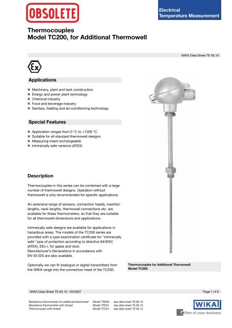
<strong>Thermocouples</strong> <strong>for</strong> <strong>Additional</strong> <strong>Thermowell</strong><br />
<strong>Model</strong> <strong>TC200</strong><br />
WIKA Data Sheet TE 65.10 · 05/2007<br />
Page 1 of 8<br />
Resistance thermometer <strong>for</strong> addtional thermowell <strong>Model</strong> TR200 see data sheet TE 60.10<br />
Resistance thermometer with thread <strong>Model</strong> TR201 see data sheet TE 60.15<br />
Thermocouple with thread <strong>Model</strong> TC201 see data sheet TE 65.15
Sensor<br />
Sensor type<br />
Type<br />
Recommended max. operating temperature<br />
Type E<br />
Class Temperature range Limiting error<br />
K (NiCr-Ni) 1200 °C<br />
J (Fe-CuNi) 800 °C<br />
E (NiCr-CuNi) 800 °C<br />
T (Cu-CuNi) 400 °C<br />
N (NiCrSi-NiSi) 1200 °C<br />
DIN EN 60 584 part 2<br />
1 - 40 °C ... + 375 °C ± 1.5 °C<br />
1 + 375 °C ... + 800 °C ± 0.0040 | t | 1)<br />
2 - 40 °C ... + 333 °C ± 2.5 °C<br />
2 + 333 °C ... + 900 °C ± 0.0075 | t | 1)<br />
In the case of type K there is a risk of blue mould between<br />
850 °C and 950 °C . We recommend the use of a sensor<br />
type N, if the working temperature fluctuates continuously<br />
in this range.<br />
The application range of these thermometers is limited by<br />
the permissible max. temperature of the thermocouple as<br />
well as the max. temperature of the thermowell material.<br />
Listed sensor types are available both as simplex or duplex<br />
thermocouples.<br />
The measuring point (hot junction) of the probe is supplied<br />
as ungrounded unless specified otherwise.<br />
Sensor limiting error<br />
A cold junction temperature of 0 °C is taken as basis with<br />
the definition of the sensor limiting error of thermocouples.<br />
Type T<br />
Class Temperature range Limiting error<br />
DIN EN 60 584 part 2<br />
1 - 40 °C ... + 125 °C ± 0.5 °C<br />
1 + 125 °C ... + 350 °C ± 0.0040 | t | 1)<br />
2 - 40 °C ... + 133 °C ± 1.0 °C<br />
2 + 133 °C ... + 350 °C ± 0.0075 | t | 1)<br />
Type N<br />
Class Temperature range Limiting error<br />
DIN EN 60 584 part 2<br />
1 - 40 °C ... + 375 °C ± 1.5 °C<br />
1 + 375 °C ... + 1000 °C ± 0.0040 | t | 1)<br />
2 - 40 °C ... + 333 °C ± 2.5 °C<br />
2 + 333 °C ... + 1200 °C ± 0.0075 | t | 1)<br />
1) | t | is the value of the temperature in °C without consideration of the sign<br />
2) Whichever is larger.<br />
Type K<br />
Class Temperature range Limiting error<br />
DIN EN 60 584 part 2<br />
1 - 40 °C ... + 375 °C ± 1.5 °C<br />
1 + 375 °C ... + 1000 °C ± 0.0040 | t | 1)<br />
2 - 40 °C ... + 333 °C ± 2.5 °C<br />
2 + 333 °C ... + 1200 °C ± 0.0075 | t | 1)<br />
ISA (ANSI) MC96.1-1982<br />
Standard 0 °C ... + 1250 °C ± 2.2 °C or 2) ± 0.75 %<br />
Special 0 °C ... + 1250 °C ± 1.1 °C or 2) ± 0.4 %<br />
Type J<br />
Class Temperature range Limiting error<br />
DIN EN 60 584 part 2<br />
1 - 40 °C ... + 375 °C ± 1.5 °C<br />
1 + 375 °C ... + 750 °C ± 0.0040 | t | 1)<br />
2 - 40 °C ... + 333 °C ± 2.5 °C<br />
2 + 333 °C ... + 750 °C ± 0.0075 | t | 1)<br />
ISA (ANSI) MC96.1-1982<br />
Standard 0 °C ... + 750 °C ± 2.2 °C or 2) ± 0.75 %<br />
Special 0 °C ... + 750 °C ± 1.1 °C or 2) ± 0.4 %<br />
Limiting error with selected temperatures in °C<br />
<strong>for</strong> thermocouples type K and type J<br />
Temperature Limiting error DIN EN 60 584<br />
(ITS 90) Class 1 Class 2<br />
°C °C °C<br />
0 ± 1.5 ± 2.5<br />
100 ± 1.5 ± 2.5<br />
200 ± 1.5 ± 2.5<br />
300 ± 1.5 ± 2.5<br />
400 ± 1.6 ± 3<br />
500 ± 2 ± 3.75<br />
600 ± 2.4 ± 4.5<br />
700 ± 2.8 ± 5.25<br />
800 ± 3.2 ± 6<br />
900 ± 3.6 ± 6.75<br />
1000 ± 4 ± 7.5<br />
1100 ± 4.4 ± 8.25<br />
1200 ± 4.8 ± 9<br />
Page 2 of 8 WIKA Data Sheet TE 65.10 · 05/2007
<strong>TC200</strong> components<br />
Fig. with parallel thread, conical thread see page 5<br />
Legend:<br />
3160 645.05<br />
? Connection head<br />
@ Extension neck<br />
A Connection to<br />
thermowell<br />
B Measuring insert<br />
C Transmitter (optional)<br />
l 1 Insertion length<br />
l 5 Measuring insert length<br />
M Extension neck length<br />
M H Neck length<br />
Connection head<br />
BS BSZ BSZ-H BSS BSS-H BVA<br />
BSZ-K<br />
BSZ-HK<br />
<strong>Model</strong> Material Cable entry Ingress protection Cap Surface finish<br />
BS aluminium M20 x 1.5 IP65 cap with 2 screws silver bronze, painted<br />
BSZ aluminium M20 x 1.5 IP65 flap cap with screw silver bronze, painted<br />
BSZ-K plastic M20 x 1.5 IP65 flap cap with screw blank<br />
BSZ-H aluminium M20 x 1.5 IP65 flap cap with screw silver bronze, painted<br />
BSZ-HK plastic M20 x 1.5 IP65 flap cap with screw blank<br />
BSS aluminium M20 x 1.5 IP65 flap cap with clip silver bronze, painted<br />
BSS-H aluminium M20 x 1.5 IP65 flap cap with clip silver bronze, painted<br />
BVA stainless steel M20 x 1.5 IP65 screw cover blank<br />
Connection head with digital indicator<br />
(option)<br />
As an optional alternative to the standard connection head<br />
the thermometer may be equipped with the digital indicator<br />
DIH10. The connection head used in this case is similar to<br />
the head model BSZ-H. For operation a 4 ... 20 mA transmitter<br />
is necessary, which is mounted to the measuring<br />
insert. The scale range of the indicator is configurated identical<br />
to the measuring range of the transmitter.<br />
Intrinsically safe versions, explosion protection type EEx (i),<br />
are also available.<br />
Fig. Connection head with digital indicator, <strong>Model</strong> DIH10<br />
WIKA Data Sheet TE 65.10 · 05/2007<br />
Page 3 of 8
Transmitter (option)<br />
Depending on used connection head a transmitter can be<br />
mounted into the thermometer.<br />
mounted instead of terminal block<br />
• mounted within the cap of the connection head<br />
– mounting not possible<br />
Mounting of two transmitters on request.<br />
Connection head<br />
Transmitter<br />
T12 T19 T24 T32 T42 T53<br />
BS – – – <br />
BSZ / BSZ-K <br />
BSZ-H / BSZ-HK • • • • • •<br />
BSS <br />
BSS-H • • • • • •<br />
BVA <br />
<strong>Model</strong> Description Explosion protection Data sheet<br />
T19 Analogue transmitter, configurable without TE 19.01<br />
T24 Analogue transmitter, PC configurable optional TE 24.01<br />
T12 Digital transmitter, PC configurable optional TE 12.01<br />
T32 Digital transmitter, HART protocol optional TE 32.01<br />
T42 Digital transmitter, PROFIBUS PA optional TE 42.01<br />
T53 Digital transmitter FOUNDATION Fieldbus and PROFIBUS PA standard TE 53.01<br />
Extension neck<br />
The extension neck is screwed to the connection head. The<br />
usual size to industrial standards is M 24 x 1.5 mm. The<br />
length of the extension neck depends on the application.<br />
Generally the extension neck serves <strong>for</strong> the bridging of an<br />
insulation. In many applications it is also used as a part<br />
cooling element between connection head and medium in<br />
order to protect any head mount transmitters from high<br />
medium temperatures. Standard material of the extension<br />
neck is stainless steel.<br />
Standard measuring insert length<br />
Measuring insert<br />
The measuring insert is made of a vibration-resistant<br />
sheathed measuring cable (MI cable). The diameter of the<br />
measuring insert shall be approx. 1 mm smaller than the<br />
hole diameter of the thermowell. Gaps of more than 0.5 mm<br />
between thermowell and measuring insert will have a<br />
negative effect on the heat transfer, and they will result in<br />
an unfavourable response behaviour of the thermometer.<br />
When fitting the measuring insert with a thermowell, it is<br />
very important to determine the correct insertion length<br />
( = thermowell length with thermowell bottom thicknesses<br />
of < 6 mm ). In this connection the fact that the measuring<br />
insert is spring-loaded (spring travel: max. 10 mm) has to<br />
be taken into account in order to ensure that the measuring<br />
insert presses against the bottom of the thermowell.<br />
Furthermore we recommend that a neck length be selected<br />
to give a standard length <strong>for</strong> the thermometer's measuring<br />
insert. This has the advantage that a measuring insert of the<br />
standard series can be used.<br />
Measuring insert Ø in mm Standard measuring insert length in mm<br />
3 275 315 375 435<br />
6 275 315 345 375 405 435 525 555 585 655 735<br />
8 275 315 345 375 405 435 525 555 585 655 735<br />
The lengths specified in this table correspond to the standard lengths. Intermediate lengths or excess lengths are possible without any problems.<br />
Possible combinations of design, extension neck diameter and connection thread<br />
Design of the screw connection Connection thread at extension neck Connection thread to the head<br />
at the extension neck Ø 11 mm Ø 12 mm Ø 14 mm<br />
Male thread G ½ B - G ½ B M 24 x 1.5<br />
G ¾ B - G ¾ B M 24 x 1.5<br />
M 14 x 1.5 - - M 24 x 1.5<br />
M 18 x 1.5 - M 18 x 1.5 M 24 x 1.5<br />
½ NPT - ½ NPT M 24 x 1.5<br />
¾ NPT - ¾ NPT M 24 x 1.5<br />
Union nut G ½ - G ½ M 24 x 1.5<br />
M 27 x 2 - M 27 x 2 M 24 x 1.5<br />
Swivel nut G ½ B - G ½ B M 24 x 1.5<br />
Extension neck without thread - - - M 24 x 1.5<br />
Extens. neck with compression fitting - G ½ B G ½ B M 24 x 1.5<br />
- M 27 x 2 M 27 x 2 M 24 x 1.5<br />
Page 4 of 8 WIKA Data Sheet TE 65.10 · 05/2007
Connection to thermowell<br />
The many possible designs ensure that the thermocouple,<br />
<strong>Model</strong> <strong>TC200</strong>, can be combined with almost all feasible<br />
thermowells. The most usual designs of connection are<br />
shown in the following drawings. Others are available on<br />
request.<br />
3160 670.03<br />
Male thread Union nut Swivel nut<br />
3160688.03A<br />
Extension neck with compression fitting<br />
(positional)<br />
Legend:<br />
l 1 Insertion length<br />
(with cylindrical threads)<br />
U 2 Insertion length<br />
(with conical threads)<br />
l 5 Measuring insert length<br />
M Extension neck length<br />
M H Neck length<br />
Ø D Extension neck Ø<br />
Ø d Measuring insert Ø<br />
Ø N Male thread<br />
Ø N 1 Female thread<br />
t 1 Threaded hole depth in<br />
thermowell<br />
K E Screw-in length by hand,<br />
with ½ NPT approx. 8.1 mm<br />
with ¾ NPT approx. 8.6 mm<br />
WIKA Data Sheet TE 65.10 · 05/2007<br />
Page 5 of 8
Electrical connection<br />
Simplex thermocouple<br />
Duplex thermocouple<br />
3166822.03<br />
The colour coding at the<br />
plus pole of the device is<br />
always deciding the<br />
correlation of polarity<br />
and connection terminal.<br />
Explosion protection (option)<br />
<strong>Thermocouples</strong> <strong>TC200</strong> are available with a type-examination<br />
certificate <strong>for</strong> "intrinsically safe" ignition protection<br />
(TÜV 02 ATEX 1793 X). These thermometers comply with<br />
the requirements of directive 94/9/EC (ATEX), EEx-i, <strong>for</strong><br />
gases and dust.<br />
Manufacturer’s Declarations in accordance with EN 50 020<br />
are also available.<br />
The classification / suitability of the instrument (permissible<br />
power P max., minimum neck length and permissible<br />
ambient temperature) <strong>for</strong> the respective category can be<br />
seen from the type test certificate and the operating<br />
instructions.<br />
Built-in transmitters have their own approval.<br />
The permissible ambient temperature ranges of the built-in<br />
transmitters can be taken from the corresponding transmitter<br />
approval.<br />
The responsibility <strong>for</strong> using suitable thermowells rests with<br />
the user.<br />
Page 6 of 8<br />
WIKA Data Sheet TE 65.10 · 05/2007
Ordering in<strong>for</strong>mation<br />
Field No.<br />
Code Features<br />
Explosion protection<br />
Z without<br />
Y according to directive 94/9/EC (ATEX) EEx-i G <strong>for</strong> gases<br />
H according to directive 94/9/EC (ATEX) EEx-i GD <strong>for</strong> gases und dust<br />
1 K according to directive 94/9/EC (ATEX) EEx-n<br />
Type and number of sensors<br />
A 1 x type K (NiCr-Ni)<br />
B 2 x type K (NiCr-Ni) 1)<br />
C 1 x type J (Fe-CuNi)<br />
D 2 x type J (Fe-CuNi) 1)<br />
2 ? other please state as additional text<br />
Sensor limiting error<br />
2 class 2 per DIN EN 60 584<br />
1 class 1 per DIN EN 60 584<br />
8 ISA (ANSI) standard to MC96.1-1982<br />
9 ISA (ANSI) special to MC96.1-1982<br />
3 ? other please state as additional text<br />
Measuring point<br />
1 insulated<br />
4 2 not insulated<br />
Measuring insert diameter<br />
1 3 mm<br />
3 6 mm<br />
4 8 mm tubing<br />
5 10 mm tubing<br />
5 ? other please state as additional text<br />
Insertion length<br />
0110 110 mm results in combination with neck length 140 mm in a standard model<br />
0140 140 mm results in combination with neck length 150 mm in a standard model<br />
0170 170 mm results in combination with neck length 150 mm in a standard model<br />
0200 200 mm results in combination with neck length 150 mm in a standard model<br />
0230 230 mm results in combination with neck length 150 mm in a standard model<br />
0260 260 mm results in combination with neck length 150 mm in a standard model<br />
0350 350 mm results in combination with neck length 150 mm in a standard model<br />
0410 410 mm results in combination with neck length 150 mm in a standard model<br />
6 length in mm, e.g. 0850 <strong>for</strong> 850 mm<br />
Neck length<br />
4 140 mm<br />
5 150 mm<br />
7 ? other please state as additional text<br />
Connection to thermowell / Extension neck diameter<br />
C1 male thread M 18 x 1.5 / diameter 11 mm not with measuring insert-Ø 8 mm<br />
B1 male thread M 14 x 1,5 / diameter 11 mm not with measuring insert-Ø 8 mm<br />
A1 male thread G 1/2 B / diameter 11 mm not with measuring insert-Ø 8 mm<br />
A3 male thread G 1/2 B / diameter 14 mm<br />
C3 male thread M 18 x 1,5 / diameter 14 mm<br />
E1 union nut M 27 x 2 / diameter 11 mm not with measuring insert-Ø 8 mm<br />
F1 union nut G 1/2 / diameter 11 mm not with measuring insert-Ø 8 mm<br />
E3 union nut M 27 x 2 / diameter 14 mm<br />
F3 union nut G 1/2 / diameter 14 mm<br />
G1 swivel nut G 1/2 B / diameter 11 mm not with measuring insert-Ø 8 mm<br />
G3 swivel nut G 1/2 B / diameter 14 mm<br />
H2 male union fitting / diameter 12 mm<br />
K2 extension neck without thread G 1/2 B, stainless steel / diameter 12 mm<br />
8 ?? other please state as additional text<br />
Connection from connection head to extension neck<br />
1 M24 x 1.5<br />
9 ? other please state as additional text<br />
WIKA Data Sheet TE 65.10 · 05/2007<br />
Page 7 of 8
Ordering in<strong>for</strong>mation, continued<br />
Field No. Code Features<br />
Connection head<br />
1 model BS (aluminium) only transmitter T19 as option possible<br />
2 model BSZ (aluminium)<br />
3 model BSZ-H (aluminium) mounting of an optional transmitter in the cap possible<br />
T model BSZ-K (plastic)<br />
S model BSZ-HK (plastic) mounting of an optional transmitter in the cap possible<br />
4 model BSS (aluminium)<br />
5 model BSS-H (aluminium) mounting of an optional transmitter in the cap possible<br />
8 model BVA (stainless steel)<br />
H<br />
BSZ-H with digital temperature indicator DIH10<br />
(set to transmitter range)<br />
only without explosion protection,<br />
<strong>for</strong> use a transmitter (4...20 mA) is required<br />
J<br />
BSZ-H with digital temperature indicator DIH10-Ex<br />
(set to transmitter range)<br />
<strong>for</strong> use a transmitter (4...20 mA) in Ex-version is required<br />
10 ? other please state as additional text<br />
Cable entry to connection head<br />
4 M20 x 1.5<br />
11 ? other please state as additional text<br />
Transmitter<br />
ZZ without<br />
TA mounted on the measuring insert<br />
12 TB mounted in the cup of the connection head<br />
<strong>Additional</strong> order info<br />
YES NO<br />
13 1 Z quality certificates see price list<br />
14 T Z additional text Please state as clearly understandable text!!<br />
1) Duplex thermocouple in combination with 2 transmitters on request<br />
Order code:<br />
1 2 3 4 5 6 7 8 9 10 11 12 13 14<br />
<strong>TC200</strong> - - - ZZ -<br />
<strong>Additional</strong> text:<br />
Specifications and dimensions given in this leaflet represent the state of engineering at the time of printing.<br />
Modifications may take place and materials specified may be replaced by others without prior notice.<br />
Page 8 of 8<br />
WIKA Data Sheet TE 65.10 · 05/2007<br />
9029575 05/2007 GB<br />
WIKA Alexander Wiegand GmbH & Co. KG<br />
Alexander-Wiegand-Straße 30<br />
63911 Klingenberg/Germany<br />
Phone (+49) 93 72/132-0<br />
Fax (+49) 93 72/132-406<br />
E-Mail info@wika.de<br />
www.wika.de