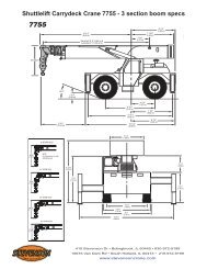
RT200/200XL
Load Charts Front Page template.indd - StevensonCrane
Load Charts Front Page template.indd - StevensonCrane
- No tags were found...

You also want an ePaper? Increase the reach of your titles
YUMPU automatically turns print PDFs into web optimized ePapers that Google loves.
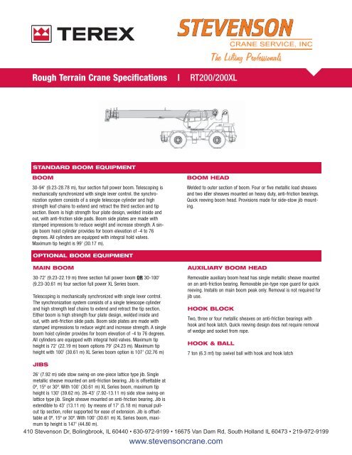
ROUGH TERRAIN CRANE<br />
<strong>RT200</strong>/<strong>200XL</strong><br />
Rough Terrain Crane Specifications | <strong>RT200</strong>/<strong>200XL</strong><br />
Cranes |<br />
STANDARD BOOM EQUIPMENT<br />
BOOM<br />
30-94' (9.23-28.78 m), four section full power boom. Telescoping is<br />
mechanically synchronized with single lever control. the synchronization<br />
system consists of a single telescope cylinder and high<br />
strength leaf chains to extend and retract the third section and tip<br />
section. Boom is high strength four plate design, welded inside and<br />
out, with anti-friction slide pads. Boom side plates are made with<br />
stamped impressions to reduce weight and increase strength. A single<br />
boom hoist cylinder provides for boom elevation of -4 to 76<br />
degrees. All cylinders are equipped with integral hold valves.<br />
Maximum tip height is 99' (30.17 m).<br />
BOOM HEAD<br />
Welded to outer section of boom. Four or five metallic load sheaves<br />
and two idler sheaves mounted on heavy duty, anti-friction bearings.<br />
Quick reeving boom head. Provisions made for side-stow jib mounting.<br />
OPTIONAL BOOM EQUIPMENT<br />
MAIN BOOM<br />
30-72' (9.23-22.19 m) three section full power boom OR 30-100'<br />
(9.23-30.61 m) four section full power XL Series boom.<br />
Telescoping is mechanically synchronized with single lever control.<br />
The synchronization system consists of a single telescope cylinder<br />
and high strength leaf chains to extend and retract the tip section.<br />
Either boom is high strength four plate design, welded inside and<br />
out, with anti-friction slide pads. Boom side plates are made with<br />
stamped impressions to reduce wight and increase strength. A single<br />
boom hoist cylinder provides for boom elevation of -4 to 76 degrees.<br />
All cylinders are equipped with integral hold valves. Maximum tip<br />
height is 72' (22.19 m) boom options 79' (24.23 m). Maximum tip<br />
height with 100' (30.61 m) XL Series boom option is 107' (32.76 m)<br />
AUXILIARY BOOM HEAD<br />
Removable auxiliary boom head has single metallic sheave mounted<br />
on an anti-friction bearing. Removable pin-type rope guard for quick<br />
reeving. Installs on main boom peak only. Removal is not required for<br />
jib use.<br />
HOOK BLOCK<br />
Two, three or four metallic sheaves on anti-friction bearings with<br />
hook and hook latch. Quick reeving design does not require removal<br />
of wedge and socket from rope.<br />
HOOK & BALL<br />
7 ton (6.3 mt) top swivel ball with hook and hook latch<br />
JIBS<br />
26' (7.92 m) side stow swing-on one-piece lattice type jib. Single<br />
metallic sheave mounted on anti-friction bearing. Jib is offsettable at<br />
0º, 15º or 30º. With 100' (30.61 m) XL Series boom, maximum tip<br />
height is 130' (39.62 m). 26-43' (7.92-13.11 m) side stow swing-on<br />
lattice type jib. Single sheave mounted on anti-friction bearing. Jib is<br />
extendible to 43' (13.11 m) by means of 17' (5.18 m) manual pullout<br />
tip section, roller supported for ease of extension. Jib is offsettable<br />
at 0º, 15º or 30º. With 100' (30.61 m) XL Series boom, maximum<br />
tip height is 147' (44.80 m).<br />
410 Stevenson Dr, Bolingbrook, IL 60440 • 630-972-9199 • 16675 Van Dam Rd, South Holland IL 60473 • 219-972-9199<br />
www.stevensoncrane.com
ROUGH TERRAIN CRANE<br />
<strong>RT200</strong>/<strong>200XL</strong><br />
STANDARD UPPERSTRUCTURE EQUIPMENT<br />
UPPERSTRUCTURE FRAME<br />
All welded one-piece structure fabricated with high tensile strength<br />
alloy steel. Counterweight is bolted to frame.<br />
TURNTABLE CONNECTION<br />
Swing bearing is a single row, ball type, with external teeth. The<br />
swing bearing is bolted to the revolving upperstructure and welded<br />
to the carrier frame.<br />
SWING<br />
A hydraulic motor drives a double planetary reduction gear for precise<br />
and smooth swing function. Swing speed (no load) is 3.0 rpm.<br />
SWING BRAKE<br />
Heavy duty multiple disc swing brake is mechanically actuated from<br />
operator’s cab by foot pedal. Brake may be locked on or used as a<br />
momentary brake. A separate 360º mechanical house lock is also<br />
provided.<br />
RATED CAPACITY INDICATOR<br />
Rated Capacity Indicator with visual and audible warning system and<br />
automatic function disconnects. Second generation pictographic display<br />
includes: boom radius, boom angle, boom length, allowable<br />
load, actual load, and percentage of allowable load registered by bar<br />
graph. Operator settable alarms provided for swing angle, boom<br />
length, boom angle, tip height, and work area exclusion zone. Antitwo<br />
block system includes audio/visual warning and automatic function<br />
disconnects.<br />
OPERATORS CAB<br />
Environmental cab with all steel construction, optimized visibility,<br />
tinted safety glass throughout, and rubber floor matting is mounted<br />
on vibration absorbing pads. The cab has a sliding door on the left<br />
side, framed sliding window on the right side, hinged tinted all glass<br />
skylight and removable front windshield to provide optimized visibility<br />
of the load open or closed. Acoustical foam padding insulates<br />
against sound and weather. The deluxe six-way adjustable operator’s<br />
seat is equipped with a mechanical suspension and includes head<br />
and arm rests<br />
CONTROLS<br />
All control levers and pedals are positioned for efficient operation.<br />
Hand operated control levers include swing, telescope, boom hoist,<br />
winch(s), shift, vernier adjustable hand throttle and 360º house lock.<br />
Switches include ignition, engine stop, two speed winch(s), lights,<br />
horn, windshield wipers, defroster, steering mode, parking brake,<br />
and outrigger controls. Foot control pedals include swing brake,<br />
boom raise, boom lower, service brakes and accelerator.<br />
INSTRUMENTATION AND ACCESSORIES<br />
In-cab gauges include air pressure, bubble level, engine oil pressure,<br />
fuel, engine temperature, voltmeter, transmission temperature, and<br />
transmission oil pressure. Indicators include low air, high water temperature/<br />
low oil pressure/high transmission temperature audio/visual<br />
warning, low coolant audio/visual warning, hoist drum rotation<br />
indicator(s), and Rated Capacity Indicator. accessories include fire<br />
extinguisher; light package including headlights, tail lights, dome<br />
light, brake lights, directional signals, four-way hazard flashers,<br />
dome light, and back up lights with audio pulsating back-up alarm;<br />
windshield washer/ wiper and skylight wiper, R.H. and L.H. rear view<br />
mirrors; dash lights; and seat belt. Circuit breakers protect electrical<br />
circuits.<br />
HYDRAULIC CONTROL VALVES<br />
Valves are mounted on the upperstructure and are easily accessible.<br />
Valves are mechanically operated and include one four spool valve<br />
for boom elevation, telescope, main winch boost, and main winch;<br />
one single spool valve for swing. High pressure regeneration feature<br />
provides 2-speed boom extension. Quick disconnects are provided<br />
for ease of installation of pressure check gauges.<br />
OPTIONAL EQUIPMENT<br />
Auxiliary Winch, Heater/Defroster, Air Conditioner, Work Lights,<br />
Revolving Amber Light, Independent Rear Wheel Steering, Roof<br />
Mounted Spotlight.<br />
STANDARD CARRIER EQUIPMENT<br />
CARRIER CHASSIS<br />
High strength chassis with four-wheel drive and four-wheel steer<br />
(4x4x4). Has box beam type construction with reinforcing cross<br />
members, a precision machined turntable mounting plate and integrally<br />
welded outrigger boxes. Decking has skid-resistant surfaces,<br />
including tool storage compartment, and access steps and handles<br />
left and right side and front and rear corners.<br />
AXLES AND SUSPENSION<br />
Rear axle is a planetary drive/steer type with 10.0" (0.25 m) of total<br />
oscillation. Automatic oscillation lockouts engage when the superstructure<br />
is swung 10˚ in either direction. An oscillation lock out<br />
override is provided. Front axle is a planetary drive/steer type, rigid<br />
mounted to the frame for increased stability.<br />
WHEELS & TIRES<br />
Disc type wheels with full tapered bead seat rim. 134" (3.40 m)<br />
wheelbase.<br />
TIRES<br />
Standard: 20.5 x 25,24 P.R. / Optional: 16.00 x 25, 28 P.R.<br />
SERVICE BRAKES<br />
Air over hydraulic drum type brakes on all four wheels: 17" x 4"<br />
(43.18 x 10.2 cm) drum brakes<br />
PARKING BRAKE<br />
Transmission mounted spring-set, air released external caliper disk<br />
type emergency/parking brake.<br />
STEERING<br />
Hydraulic four-wheel power steering for two-wheel, four-wheel, or<br />
crab steer is easily controlled by steering wheel. A rear axle centering<br />
light is provided.
ROUGH TERRAIN CRANE<br />
<strong>RT200</strong>/<strong>200XL</strong><br />
STANDARD CARRIER EQUIPMENT (CONTINUED)<br />
Turning radius to center of outside tire.<br />
(16.00 x 25) (20.5 x 25)<br />
Two-wheel: 34’ 8.81" (10.5 m) 34' 10.38" (10.63)<br />
Four-wheel: 19' 3.44 (5.88 m) 19' 5" (5.92 m)<br />
TRANSMISSION<br />
Range-shift type power-shift transmission with integral torque converter has<br />
neutral safety start, 6 speeds forward, and 6 speeds reverse. Automatic pulsating<br />
back-up alarm.<br />
MULTI-POSITION OUT & DOWN OUTRIG-<br />
GERS<br />
Fully independent hydraulic outriggers may be utilized fully extended, in their<br />
1/2 extended position, or fully retracted. Easily removable steel floats, each<br />
with an area of 254 2 (1 639 cm 2 ) stow on the carrier frame. Complete contorls<br />
and sight leveling bubble are located in the operators’ cab.<br />
OPTIONAL EQUIPMENT<br />
Cold Weather Starting Aid, Immersion Heater, Pintle Hook, Clearance Lights,<br />
Front Mounted Winch - 20,000 lb (9 072 kg), Independent Rear or Four Mode<br />
Rear Wheel Steer.<br />
HYDRAULIC SYSTEM<br />
HYDRAULIC PUMPS<br />
Three gear type pumps, one single and two in tandem, driven off the transmission.<br />
Combined system capability is 113 gpm (427.7 lpm). Includes manual<br />
pump disconnect.<br />
Main Winch Pump<br />
53 gpm (200.7 lpm) @ 3,500 psi (246.1 kg/cm 2 )<br />
Boom Hoist and Telescope Pump<br />
39 gpm (147.6 lpm) @ 3,500 psi (246.1 kg/cm 2 )<br />
Power Steering, Outrigger and Winch Boost Pump<br />
21 gpm (79.5 lpm) @ 2,500 psi (175 kg/cm 2 ) Always live even when<br />
pump disconnect is actuated.<br />
MAIN WINCH SPECIFICATIONS<br />
Hydraulic winch with bent axis piston motor an planetary reduction provides<br />
2-speed operation with equal speeds for power up and down. Winch is<br />
equipped with an integral automatic brake, a grooved drum with tapered<br />
flanges for improved rope spooling, a spring loaded cable roller and an electronic<br />
drum rotation indicator.<br />
Performance LO-Range HI-Range<br />
Max line speed (no load)<br />
First layer 205 fpm (62.5 m/min) 329 fpm (100.3 m/min.)<br />
Fifth layer 297 fpm (90.5 m/min) 475 fpm (144.8 m/min.)<br />
Max. line pull-first layer 12,512 lb (5 675 kg) 7,298 lb (3 310 kg)<br />
Max. line pull-fifth layer 8,662 lb (3 929 kg) 5,052 lb (2 292 kg)<br />
Permissible line pull 9,000 lb (4 082 kg)<br />
Drum Dimensions<br />
Drum Capacity<br />
10.62" (270 mm) drum diameter Max. Storage: 598' (182.3 m)<br />
17.53" (445 mm) length 6th layer is not a working layer<br />
18.25" (464 mm) flange dia. Max. useable: 479' (146.0 m)*<br />
Cable: 5/8" x 450' (16 mm x 137.2 m)<br />
Cable type: 5/8" (16 mm) 6x19 IWRC IPS right regular lay, preformed.<br />
Min. breaking strength 17.9 tons (16.2 mt)<br />
*Based on minimum flange height above top layer to comply with ANSI B30.5<br />
OPTIONAL AUXILIARY WINCH<br />
Hydraulic winch with bent axis piston motor, power up and down, equal<br />
speed, planetary reduction with integral automatic brake, cable roller, and<br />
rotation indicator.<br />
Performance<br />
Drum Dimensions and Capacity<br />
(Same as main winch)<br />
(Same as main winch)<br />
FILTRATION<br />
Full flow oil filtration system with bypass protection includes a removable 60<br />
mesh (250 micron) suction screen-type filter and 5 micron replaceable return<br />
line filter.<br />
HYDRAULIC RESERVOIR<br />
All steel, welded construction with internal baffles and diffuser. Provides easy<br />
access to filters and is equipped with an external sight level gauge. The<br />
hydraulic tank is pressurized to aid in keeping out contaminants and in<br />
reducing potential pump cavitation. Capacity is 94 gal (355 liters). Swingaway<br />
hydraulic oil cooler is standard<br />
OPTIONAL HOIST LINE<br />
Main winch and optional auxiliary winch: 5/8" (16 mm) rotation resistant<br />
compacted strand 18 x 19 or 19 x 19. Min. breaking strength 22.6 tons (20.6<br />
mt).<br />
ENGINE SPECIFICATIONS<br />
Standard<br />
Make and Model Cummins 6BTA5.9<br />
Type<br />
6 Cylinder<br />
Bore and Stroke 4.02x4.72" (102x120 mm)<br />
Displacement 359 cu in (5.9 L)<br />
Max. Gross HP 130 hp (97 kw)@2500 rpm<br />
Max. Gross Torque 384 lb•ft (521 N•m) @1200 rpm<br />
Aspiration<br />
Turbocharged<br />
Air Filter<br />
Dry Type<br />
Electrical System 12 volt<br />
Alternator<br />
102 amp<br />
Battery<br />
(2) 12V-1600 C.C.A.<br />
Fuel Capacity 50 gal (189 L)<br />
PERFORMANCE (STANDARD ENGINE)<br />
Trans-<br />
Max.<br />
mission Forward Max. Tractive Gradeability<br />
Range Gear Drive Speed Effort @ Stall<br />
Low 1 4-Wheel 2.3 mph 37,856 lb 112.34%<br />
3.7 km/h 17 171 kg<br />
2 4-Wheel 4.4 mph 19,254 lb 39.84%<br />
7.1 km/h 8 734 kg<br />
3 4-Wheel 12.4 mph 6,431 lb 11.10%<br />
20.0 km/h 2 917 kg<br />
High 1 2-Wheel 5.0 mph 16,893 lb 34.04%<br />
8.0 km/h 7 663 kg<br />
2 2-Wheel 9.5 mph 8,589 lb 15.59%<br />
15.3 km/hr 3 896 kg<br />
3 2-Wheel 24.5 mph 2,849 lb 3.77%<br />
39.4 km/h 1 292 kg<br />
All performance data is based on a gross vehicle weight of 52,000 lb (23 583<br />
kg). 16:00 x 25 tires, 4x4 drive. Performance may vary due to engine performance.<br />
Gradeability data is theoretical and is limited by tire slip, machine stability,<br />
or engine oil pan design.
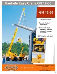
GENERAL DIMENSIONS<br />
1. Dimensions given assume the boom is fully retracted in travel position and 16:00 x 25 tires.<br />
20.5 tires reduce heights 1.0 (25 mm)<br />
3. Track width: 6' 7.50" (2.02 m) 16:00 x 25 tires<br />
6' 10.5" (2.10 m) 20.5 x 25 tires<br />
2. Minimum ground clearance under transmission - 20.62" (.52m)<br />
axle bowls - 19.12" (.49 m)<br />
tire rods - 20.38" (.52 m)<br />
4. Width of carrier: 8' (2.44 m) 16:00 x 25 tires<br />
8' 8" (2.64 m) 20.5 x 25 tires<br />
Tire to frame angle 16:00 tires 20.5 tires<br />
Approach angle: 25.1º 24.1º<br />
Departure angle: 23.1º 22.2º<br />
WEIGHTS &<br />
AXLE LOADS<br />
GROSS<br />
WEIGHT<br />
LB<br />
UPPER FACING<br />
FRONT<br />
FRONT REAR<br />
GROSS<br />
WEIGHT<br />
KG<br />
UPPER FACING<br />
FRONT<br />
FRONT REAR<br />
Basic Crane with 10,000 lb (4 536 kg) Counterweight 55,930 28,972 26,958 25 369 13 141 12 228<br />
Add Options:<br />
26' (7.92 m) Swing-on Jib (Stowed) + 1100 + 2,000 - 900 + 499 + 907 - 408<br />
26'-43' (7.92-13.11 m) Swing-on Jib (Stowed) + 1500 + 2,600 - 1,100 + 680 + 1 179 - 499<br />
Auxiliary Boom Head + 100 + 300 - 200 + 45 + 136 - 91<br />
Auxiliary Winch with Wire Rope, Controls, Etc. + 115 - 25 + 140 + 52 - 11 + 63<br />
30 ton (27.2 mt) 4 Sheave Hook Block + 655 + 1,071 - 416 + 297 + 486 - 189<br />
30 ton (27.2 mt) 3 Sheave Hook Block + 670 + 1,099 - 429 + 304 + 498 - 194<br />
25 ton (22.6 mt) 2 Sheave Hook Block + 682 + 1,117 - 435 + 309 + 507 - 198<br />
7 ton (6.3 mt) Hook and Ball (in tool box) + 240 + 290 - 50 + 109 + 130 - 21<br />
Pintle Hook: Front + 45 + 60 - 15 + 20 + 27 - 7<br />
Rear + 45 - 25 + 70 + 20 - 11 + 31<br />
Substitute:<br />
72' (22.19 m) Full Power 3-Section Boom - 3190 - 4,335 + 1,145 - 1 445 - 1 965 + 520<br />
100' (30.61 m) Full Power 4-Section Boom + 533 + 1,986 - 1,453 + 242 + 901 - 659<br />
16.00 x 25 Tires - 360 - 180 - 180 - 164 - 82 - 82<br />
Note: Weights are for Terex supplied equipment and are subject to 2% variation due to manufacturing tolerances.<br />
TEREX Cranes<br />
106-12th Street S.E.<br />
Waverly, Iowa 50677-9466 USA<br />
TEL (319) 352-3920 FAX (319) 352-5727<br />
EMAIL inquire@terexwaverly.com<br />
WEB terex.com<br />
WE RESERVE THE RIGHT TO AMEND THESE SPECIFICATIONS AT ANY TIME WITHOUT NOTICE. THE ONLY WARRANTY APPLICABLE IS OUR STANDARD WRITTEN WARRANTY APPLICABLE TO THE PARTICULAR PRODUCT AND SALE.<br />
WE MAKE NO OTHER WARRANTY, EXPRESSED OR IMPLIED.<br />
©TEREX CRANES, INC 2005 PRINTED IN U.S.A MARCH 7, 2005
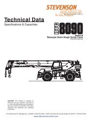
Range Diagram and Lifting Capacity | RT230<br />
Cranes |<br />
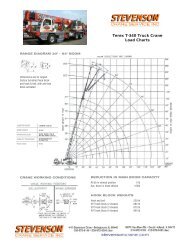
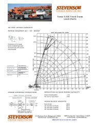
30 TON LIFTING CAPACITY<br />
RANGE DIAGRAM 30' - 94' BOOM<br />
Dimensions are for largest<br />
factory furnished hook block<br />
and hook & ball, with anti-two<br />
block activated<br />
COUNTER WEIGHT<br />
BOOM LENGTH<br />
OUTRIGGER SPREAD<br />
STABILITY PERCENTAGE<br />
PCSA CLASS<br />
W/AUX. WINCH 8,900 LB<br />
W/O AUX. WINCH 10,000 LB<br />
30'-94'<br />
19'<br />
ON OUTRIGGERS 85%<br />
ON TIRES 75%<br />
10-118<br />
CRANE WORKING CONDITIONS<br />
REDUCTION IN MAIN BOOM CAPACITY<br />
All jib in stowed position<br />
0 lb<br />
ax. boom in head sheave<br />
100lb<br />
HOOK BLOCK WEIGHTS<br />
Hook and ball<br />
Hook block (2 sheave)<br />
Hook block (3 sheave)<br />
Hook block (4 sheave)<br />
240 lb<br />
680 lb<br />
670 lb<br />
653 lb
ROUGH TERRAIN CRANE<br />
RT230<br />
LIFTING CAPACITIES<br />
CAUTION: Do not use this specification sheet as a load rating chart. The format of data is not consistent with<br />
the machine chart and may be subject to change<br />
ON OUTRIGGERS - FULLY EXTENDED<br />
BOOM LENGTH 30’ BOOM LENGTH 39’ BOOM LENGTH 50’<br />
LOADED LOADED LOADED<br />
LOAD BOOM OVER BOOM OVER BOOM OVER LOAD<br />
RADIUS ANGLE FRONT 360º ANGLE FRONT 360º ANGLE FRONT 360º RADIUS<br />
(FT) (DEG) (LB) (LB) (DEG). (LB) (LB) (DEG). (LB) (LB) (FT)<br />
10 63.0 60,000* 60,000* 69.4 46,600* 46,600* 10<br />
12 58.5 50,100* 50,100* 55.2 46,600* 46,600* 71.7 44,500* 44,500* 12<br />
15 51.4 40,100* 40,100* 61.2 40,000* 40,000* 68.0 38,500* 38,500* 15<br />
20 37.4 30,100* 30,100* 52.3 30,000* 30,000* 61.6 30,000* 30,000* 20<br />
25 13.7 22,800* 22,900* 42.0 23,600* 23,600* 54.8 24,000* 24,000* 25<br />
30 ** 28.8 18,600* 18,600 47.3 19,100* 19,100* 30<br />
35 ** 38.7 15,500 15,100 35<br />
40 27.9 12,100 11,800 40<br />
45 7.9 9,600 9,300 45<br />
50 ** 50<br />
55 55<br />
60 60<br />
65 65<br />
70 70<br />
75 75<br />
80 80<br />
85 85<br />
USE THESE CHARTS ONLY<br />
WHEN ALL OUTRIGGERS<br />
ARE FULLY EXTENDED
ROUGH TERRAIN CRANE<br />
RT230<br />
LIFTING CAPACITIES<br />
CAUTION: Do not use this specification sheet as a load rating chart. The format of data is not consistent with<br />
the machine chart and may be subject to change<br />
ON OUTRIGGERS - FULLY EXTENDED<br />
BOOM LENGTH 61' BOOM LENGTH 72' BOOM LENGTH 83' BOOM LENGTH 94'<br />
LOADED LOADED LOADED LOADED<br />
LOAD BOOM OVER BOOM OVER BOOM OVER BOOM OVER LOAD<br />
RADIUS ANGLE FRONT 360º ANGLE FRONT 360º ANGLE FRONT 360º ANGLE FRONT 360º RADIUS<br />
(FT) (DEG) (LB) (LB) (DEG) (LB) (LB) (DEG) (LB) (LB) (DEG) (LB) (LB) (FT)<br />
10 10<br />
12 12<br />
15 72.1 36,000* 36,000* 15<br />
20 67.1 29,500* 29,500* 70.8 27,400* 27,400* 20<br />
25 61.9 24,000* 24,000* 66.5 23,100* 23,100* 69.8 19,000* 19,000* 72.2 15,300* 15,300* 25<br />
30 56.3 19,400* 19,400* 62.0 19,600* 19,600* 66.0 15,900* 15,900* 69.0 13,100* 13,100* 30<br />
35 50.4 15,700 15,400 57.4 15,900 15,500 62.2 13,800* 13,800* 65.7 11,400* 11,400* 35<br />
40 43.9 12,400 12,100 52.5 12,600 12,300 58.1 12,000* 12,000* 62.2 10,000* 10,000* 40<br />
45 36.5 10,000 9,800 47.2 10,200 9,900 53.9 10,300 10,000 58.7 8,800* 8,800* 45<br />
50 27.3 8,200 7,900 41.4 8,400 8,100 49.5 8,500 8,300 55.1 7,900* 7,900* 50<br />
55 13.0 6,700 6,500 34.8 7,000 6,800 44.7 7,100 6,900 51.2 7,100* 7,000 55<br />
60 ** 26.9 5,800 5,600 39.5 6,000 5,800 47.2 6,100 5,800 60<br />
65 15.5 4,800 4,600 33.6 5,000 4,800 42.8 5,100 4,900 65<br />
70 ** 26.6 4,200 4,100 38.0 4,300 4,200 70<br />
75 17.0 3,500 3,400 32.7 3,700 3,500 75<br />
80 ** 26.4 3,100 2,900 80<br />
85 18.1 2,600 2,400 85<br />
**MAXIMUM CAPACITY AT 0 DEGREE BOOM ANGLE<br />
BOOM LENGTH 30' BOOM LENGTH 39' BOOM LENGTH 50' BOOM LENGTH 61' BOOM LENGTH 72' BOOM LENGTH 83' BOOM LENGTH 94'<br />
LOAD OVER LOAD OVER LOAD OVER LOAD OVER LOAD OVER LOAD OVER LOAD OVER<br />
RADIUS FRONT 360º RADIUS FRONT 360º RADIUS FRONT 360º RADIUS FRONT 360º RADIUS FRONT 360º RADIUS FRONT 360º RADIUS FRONT 360º<br />
(FT) (LB) (LB) (FT) (LB) (LB) (FT) (LB) (LB) (FT) (LB) (LB) (FT) (LB) (LB) (FT) (LB) (LB) (FT) (LB) (LB)<br />
25.6 21,900 21,900 34.3 15,200 14,900 45.3 9,400 9,100 56.3 6,300 6,100 67.3 4,400 4,200 78.3 3,100 2,900 89.3 2,100 2,000
ROUGH TERRAIN CRANE<br />
RT230<br />
LIFTING CAPACITIES<br />
CAUTION: Do not use this specification sheet as a load rating chart. The format of data is not consistent with<br />
the machine chart and may be subject to change<br />
ON OUTRIGGERS - MID POSITION<br />
BOOM LENGTH 30' BOOM LENGTH 39' BOOM LENGTH 50' BOOM LENGTH 61' BOOM LENGTH 72' BOOM LENGTH 83' BOOM LENGTH 94'<br />
LOADED LOADED LOADED LOADED LOADED LOADED LOADED<br />
LOAD BOOM BOOM BOOM BOOM BOOM BOOM BOOM LOAD<br />
RADIUS ANGLE 360º ANGLE 360º ANGLE 360º ANGLE 360º ANGLE 360º ANGLE 360º ANGLE 360º RADIUS<br />
(FT) (DEG). (LB) (DEG) (LB) (DEG). (LB) (DEG) (LB) (DEG) (LB) (DEG) (LB) (DEG) (LB) (FT)<br />
10 63.0 60,000* 69.4 46,600* 10<br />
12 58.5 50,100* 66.2 46,600* 71.7 44,500* 12<br />
15 51.4 38,000 61.2 38,700 68.0 38,500* 72.1 36,000* 15<br />
20 37.4 21,500 52.3 22,300 61.6 22,700 67.1 23,000 70.8 23,100 20<br />
25 13.7 13,800 42.0 14,700 54.8 15,200 61.9 15,400 66.5 15,600 69.8 15,700 72.2 15,300* 25<br />
30 ** 28.8 10,300 47.3 10,900 56.3 11,100 62.0 11,200 66.0 11,400 69.0 11,400 30<br />
35 ** 38.7 8,000 50.4 8,300 57.4 8,400 62.2 8,500 65.7 8,600 35<br />
40 27.9 5,900 43.9 6,300 52.5 6,500 58.1 6,600 62.2 6,600 40<br />
45 7.9 4,400 36.5 4,800 47.2 5,000 53.9 5,100 58.7 5,200 45<br />
50 ** 27.3 3,600 41.4 3,800 49.5 4,000 55.1 4,100 50<br />
55 13.0 2,600 34.8 2,900 44.7 3,100 51.2 3,200 55<br />
60 ** 26.9 2,100 39.5 2,300 47.2 2,400 60<br />
65 15.5 1,500 33.6 1,700 42.8 1,800 65<br />
70 26.6 1,100 38.0 1,300 70<br />
**MAXIMUM CAPACITY AT 0 DEGREE BOOM ANGLE<br />
BOOM LENGTH 30' BOOM LENGTH 39' BOOM LENGTH 50' BOOM LENGTH 61' BOOM LENGTH 72' BOOM LENGTH 83' BOOM LENGTH 94'<br />
USE THESE CHARTS ONLY WHEN<br />
ALL OUTRIGGERS ARE PINNED IN<br />
MID POSITION<br />
LOAD LOAD LOAD LOAD LOAD LOAD LOAD<br />
RADIUS 360º RADIUS 360º RADIUS 360º RADIUS 360º RADIUS 360º RADIUS 360º RADIUS 360º<br />
(FT) (LB) (FT) (LB) (FT) (LB) (FT) (LB) (FT) (LB) (FT) (LB) (FT) (LB)<br />
25.6 12,900 34.3 7,600 45.3 4,200 56.3 2,400 67.3 1,200
ROUGH TERRAIN CRANE<br />
RT230<br />
LIFTING CAPACITIES<br />
CAUTION: Do not use this specification sheet as a load rating chart. The format of data is not consistent with<br />
the machine chart and may be subject to change<br />
ON OUTRIGGERS - RETRACTED<br />
BOOM LENGTH 30' BOOM LENGTH 39' BOOM LENGTH 50' BOOM LENGTH 61' BOOM LENGTH 72' BOOM LENGTH 83' BOOM LENGTH 94'<br />
LOADED LOADED LOADED LOADED LOADED LOADED LOADED<br />
LOAD BOOM BOOM BOOM BOOM BOOM BOOM BOOM LOAD<br />
RADIUS ANGLE 360º ANGLE 360º ANGLE 360º ANGLE 360º ANGLE 360º ANGLE 360º ANGLE 360º RADIUS<br />
(FT) (DEG). (LB) (DEG) (LB) (DEG). (LB) (DEG) (LB) (DEG) (LB) (DEG) (LB) (DEG) (LB) (FT)<br />
10 63.0 32,800 69.4 33,400 10<br />
12 58.5 23,600 66.2 24,200 71.7 24,600 12<br />
15 51.4 15,800 61.2 16,500 68.0 16,900 72.1 17,100 15<br />
20 37.4 9,100 52.3 9,800 61.6 10,300 67.1 10,500 70.8 10,600 20<br />
25 13.7 5,300 42.0 6,200 54.8 6,700 61.9 6,900 66.5 7,100 69.8 7,200 72.2 7,200 25<br />
30 ** 28.8 3,900 47.3 4,400 56.3 4,700 62.0 4,900 66.0 5,000 69.0 5,100 30<br />
35 ** 38.7 2,900 50.4 3,200 57.4 3,400 62.2 3,500 65.7 3,600 35<br />
40 27.9 1,700 43.9 2,100 52.5 2,300 58.1 2,400 62.2 2,500 40<br />
45 36.5 1,200 47.2 1,400 53.9 1,500 58.7 1,600 45<br />
50 49.5 900 55.1 1,000 50<br />
**MAXIMUM CAPACITY AT 0 DEGREE BOOM ANGLE<br />
BOOM LENGTH 30' BOOM LENGTH 39' BOOM LENGTH 50' BOOM LENGTH 61' BOOM LENGTH 72' BOOM LENGTH 83' BOOM LENGTH 94'<br />
USE THESE CHARTS WHEN ALL<br />
OUTRIGGER BEAMS ARE NOT IN<br />
EITHER THE MID OR FULLY<br />
EXTENDED POSITION<br />
LOAD LOAD LOAD LOAD LOAD LOAD LOAD<br />
RADIUS 360º RADIUS 360º RADIUS 360º RADIUS 360º RADIUS 360º RADIUS 360º RADIUS 360º<br />
(FT) (LB) (FT) (LB) (FT) (LB) (FT) (LB) (FT) (LB) (FT) (LB) (FT) (LB)<br />
25.6 4,900 34.3 2,400
ROUGH TERRAIN CRANE<br />
RT230<br />
LIFTING CAPACITIES<br />
CAUTION: Do not use this specification sheet as a load rating chart. The format of data is not consistent with<br />
the machine chart and may be subject to change<br />
SIDE STOW JIB ON FULLY EXTENDED OUTRIGGERS<br />
26' OFFSETTABLE JIB/NO PULL OUT INSTALLED 43' OFFSETTABLE JIB/PULL OUT RETRACTED<br />
0º OFFSET 15º OFFSET 30º OFFSET 0º OFFSET 15º OFFSET 30º OFFSET<br />
LOADED LOAD LOAD LOAD LOAD LOAD LOAD LOADED<br />
BOOM RADIUS RADIUS RADIUS RADIUS RADIUS RADIUS BOOM<br />
ANGLE (REF) 360º (REF) 360º (REF) 360º (REF) 360º (REF) 360º (REF) 360º ANGLE<br />
(DEG) (FT) (LB) (FT) (LB) (FT) (LB) (FT) (LB) (FT) (LB) (FT) (LB) (DEG)<br />
75 35 9,100 40 7,400 45 5,600 41 5,100 50 3,400 62 2,700 75<br />
73 39 8,600 43 6,800 49 5,300 45 4,800 54 3,300 65 2,700 73<br />
71 43 8,100 47 6,300 52 5,000 49 4,500 58 3,200 68 2,600 71<br />
68 49 7,300 52 5,600 56 4,500 54 4,100 64 3,000 72 2,500 68<br />
65 60 5,500 62 4,600 61 4,100 60 3,800 70 2,900 77 2,500 65<br />
62 60 5,500 62 4,600 66 3,700 67 3,600 74 2,800 82 2,400 62<br />
59 64 4,800 67 4,100 71 3,400 75 3,400 81 2,700 88 2,400 59<br />
55 70 4,100 73 3,600 78 3,000 82 3,100 89 2,600 95 2,300 55<br />
51 76 3,500 79 3,200 84 2,800 88 2,900 96 2,500 100 2,300 51<br />
47 82 2,800 86 2,600 89 2,500 95 2,500 101 2,100 105 2,000 47<br />
43 87 2,300 91 2,200 93 2,300 101 2,100 107 1,700 110 1,600 43<br />
38 93 1,800 97 1,800 98 1,800 108 1,700 113 1,300 115 1,300 38<br />
32 100 1,400 102 1,400 104 1,400 116 1,200 119 1,000 121 1,000 32<br />
25 106 1,000 108 1,000 108 1,000 25<br />
Notes For Jib Capacities:<br />
A. For all boom lengths less than the maximum with a jib erected, the rated loads are determined by boom angle only In the appropriate column.<br />
B. For boom angle not shown, use the capacity of the next lower boom angle.<br />
C. Listed radii are for extended main boom only.
ROUGH TERRAIN CRANE<br />
RT230<br />
LIFTING CAPACITIES<br />
CAUTION: Do not use this specification sheet as a load rating chart. The format of data is not consistent with<br />
the machine chart and may be subject to change<br />
ON TIRES<br />
MAX<br />
16:00 X 25-28 PR<br />
BOOM<br />
PICK & CARRY<br />
RADIUS LENGTH STATIONARY CREEP 2.5 MPH<br />
(FT) (FT) 360º STRAIGHT OVER FRONT<br />
10 30 23,600 45,900 36,100 26,500<br />
12 30 17,300 39,700 31,100 22,600<br />
15 39 13,000 27,400 25,400 18,200<br />
20 39 8,000 16,200 16,200 13,200<br />
25 50 5,200 11,000 11,000 9,700<br />
30 50 3,200 7,900 7,900 7,500<br />
35 50 1,900 6,100 6,100 6,000<br />
40 61 1,200 4,900 4,900 4,800<br />
45 61 3,800 3,800 3,800<br />
50 61 2,700 2,700 2,700<br />
55 61 2,000 2,000 2,000<br />
60 72 1,500 1,500 1,500<br />
65 72 1,100 1,100 1,100<br />
20:50 X 25-24 PR<br />
PICK & CARRY<br />
STATIONARY CREEP 2.5 MPH<br />
360º STRAIGHT OVER FRONT<br />
24,000 44,200 34,700 23,700<br />
19,000 35,300 29,900 20,200<br />
14,100 27,400 24,400 16,100<br />
8,400 16,600 16,600 11,500<br />
5,400 11,200 11,200 8,300<br />
3,400 8,100 8,100 6,300<br />
2,000 6,100 6,100 5,000<br />
1,300 4,900 4,900 3,900<br />
3,900 3,900 3,100<br />
2,800 2,800 2,400<br />
2,100 2,100 1,800<br />
1,500 1,500 1,300<br />
1,200 1,200 900<br />
Notes For On Tire Capacities:<br />
A. For Pick and Carry operations, boom must be<br />
centered over the front of the crane with swing<br />
brake and lock engaged. Use minimum boom<br />
point height and keep load close to ground surface.<br />
B. The load should be restrained from swinging.<br />
NO ON TIRE OPERATION WITH JIB ERECTED.<br />
C. Without outriggers, never maneuver the boom<br />
beyond listed load radii for applicable tires to<br />
ensure stability.<br />
D. Creep speed Is crane movement of less than<br />
200' (61 m) in a 30 minute period and not<br />
exceeding 1.0 mph (1.6 km/h).<br />
E. Refer to General Notes for additional information.<br />
RECOMMENDED TIRE PRESSURE<br />
TIRE SIZE STATIONARY CREEP 2 1/2 MPH TRAVEL<br />
16:00 x 25-28 PR 115 PSI 115 PSI 95 PSI 95 PSI<br />
20:50 x 25-24 PR 95 PSI 95 PSI 70 PSI 70 PSI<br />
MAXIMUM PERMISSIBLE HOIST LINE LOAD<br />
LINE PARTS 1 2 3 4 5 6 7<br />
MAX LOAD 9,080 18,160 27,240 36,320 45,400 54,480 63,560<br />
BOOM HEAD 2 3-D 2-3 1-4-D 2-3-4 2-3-4-D 1-2-3-4<br />
HOOK BLOCK D 3 3-D 1-4 2-3-D 2-3-4 2-3-4-D<br />
WIRE ROPE:<br />
5/8" ROTATION RESISTANT 18X19 OR 19X19 MINIMUM BREAKING<br />
STRENGTH -22.7 TONS<br />
5/8" 6X19 OR 6X37 IWRC IPS PREFORMED RIGHT<br />
REGULAR LAY MINIMUM BREAKING STRENGTH - 17.9 TONS
General Notes | <strong>RT200</strong><br />
Cranes |<br />
GENERAL<br />
1. Rated loads as shown on Lift Charts pertain to this machine as originally manufactured<br />
and equipped. Modifications to the machine or use of optional equipment or<br />
other than that specified can result in a reduction of capacity.<br />
2. Construction equipment can be hazardous if improperly operated or maintained.<br />
Operation and maintenance of this machine shall be in compliance with the information<br />
in the Operator’s, Parts and Safety Manuals supplied with this machine. If<br />
These manuals are missing, order replacements from the manufacturer through<br />
your distributor.<br />
3. These warnings to not constitute all of the operating conditions for the crane. The<br />
operator and job site supervision must read the OPERATORS MANUAL, CIMA SAFE-<br />
TY MANUAL, APPLICABLE OSHA REGULATIONS, AND SOCIETY OF MECHANICAL<br />
ENGINEERS (ASME) SAFETY STANDINGS FOR CRANES.<br />
4. This crane and its load ratings are in accordance with POWER CRANE & SHOVEL<br />
ASSOCIATION, STANDARD NO.4 SAE CRANE LOAD STABILITY TEST CODE J765A,<br />
SAE METHOD OF TEST FOR CRANE STRUCTURE J1063 AND APPLICABLE SAFETY<br />
CODE FOR CRANES, DERRICKS AND HOISTS, ASME/ANSI B30.5<br />
DEFINITIONS<br />
1. LOAD RADIUS - The horizontal distance from the axis of rotation before loading to<br />
the center of the vertical hoist line or tackle with a load applied.<br />
2. LOADED BOOM ANGLE - It is the angle between the boom base section and the horizontal,<br />
after lifting the rated load at the rated radius. the boom angle before loading<br />
should be greater to account for deflections. The loaded boom angle combined with<br />
boom length give only an approximation of the operating radius.<br />
3. WORKING AREA - Areas measured in a circular arc about the centerline of rotation<br />
as shown in the diagram.<br />
4. FREELY SUSPENDED LOAD - Load hanging free with no direct external force applied<br />
except by the hoist rope.<br />
5. SIDE LOAD - Horizontal force applied to he lifted load either on the ground or in the<br />
air.<br />
6. NO LOAD STABILITY LIMIT - The stability limit radius shown on the range diagrams<br />
is the radius beyond which it is not permitted to position the boom, when the boom<br />
angle is less than the minimum shown on the applicable load chart, because the<br />
machine can overturn without any load.<br />
7. BOOM SIDE OF CRANE - The side of the crane over which the boom is positions<br />
when in OVER SIDE working position.<br />
SET-UP<br />
1. Crane load ratings are based on the crane being leveled and standing on a firm,<br />
uniform supporting surface.<br />
2. Crane load ratings on outriggers are based on all outrigger beams being fully<br />
extended or in the case of partial extension ratings mechanically pinned in the<br />
appropriate position, and the tires free of the supporting surface.<br />
3. Crane load ratings on tires depend on appropriate inflation pressure and the tire<br />
conditions. Caution must be exercised when increasing air pressures in tires.<br />
Consult Operator’s Manual for precautions.<br />
4. Use of jibs, lattice-type boom extensions, or fourth section pullouts extended is not<br />
permitted for pick and carry operations.<br />
5. Consult appropriate section of the Operator’s and Service Manual for more exact<br />
description of hoist line reeving.<br />
6. The use of more parts of line than required by the load may result in having insufficient<br />
rope to allow the hook block to reach the ground.<br />
7. Properly maintained wire rope is essential for save crane operation. Consult<br />
Operator’s Manual for proper maintenance and inspection requirements.<br />
8. When spin-resistant wire rope is used, the allowable rope loading shall be the<br />
breaking strength divided by five (5), unless otherwise specified by the wire rope<br />
manufacturer.<br />
9. Do not elevate the boom above 60° unless the boom is positioned in-line with the<br />
crane’s chassis or the outrigger are extended. Failure to observe this warning may<br />
result in loss of stability.<br />
OPERATION<br />
1. CRANE LOAD RATINGS MUST NOT BE EXCEEDED. DO NOT ATTEMPT TO TIP THE<br />
CRANE TO DETERMINE ALLOWABLE LOADS.<br />
2. When either radius or boom length, or both, are between listed values, the smaller<br />
of the two listed load ratings shall be used.<br />
3. Do not operate at longer radii than those listed on the applicable load rating chart<br />
(cross hatched areas shown on range diagrams.)<br />
4. The boom angles shown on the Capacity Chart give an approximation of the operating<br />
radius for a specified boom length.The boom angle, before loading, should be<br />
greater to account for boom deflection. It may be necessary to retract the boom if<br />
maximum boom angle is insufficient to maintain rated radius.<br />
5. Power telescoping boom sections must be extended equally.<br />
6. Rated loads include the weight of hook block, slings, and auxiliary lifting devices.<br />
Their weights shall be subtracted from the listed rated load to obtain the net load<br />
that can be lifted. When lifting over the jib the weight of any hook block, slings, and<br />
auxiliary lifting devices at the boom head must be added to the load. When jibs are<br />
erected but unused add two (2) times the weight of any hook block, slings, and<br />
auxiliary lifting devices at the jib head to the load.<br />
7. Rated loads do not exceed 85% on outriggers or 75% on tires, of the tipping load<br />
as determined by SAE Crane Stability Test Code J765a. Structural strength ratings<br />
in chart are indicated with an asterisk (*).<br />
8. Rated loads are based on freely suspended loads. No attempt shall be made to drag<br />
a load horizontally on the ground in any direction.<br />
9. The user shall operate at reduced ratings to allow for adverse job conditions, such<br />
as: soft or uneven ground, out of level conditions, high winds, side loads, pendulum<br />
action, jerking or sudden stopping of loads, hazardous conditions, experience of<br />
personnel, two machine lifts, traveling with loads, electric wires, etc. (side pull on<br />
boom or jib is hazardous). Derating of the cranes lifting capacity is required when<br />
wind speed exceeds 20 MPH. The center of the lifted load must never be allowed to<br />
move more then 3* off the center line of the base boom section due to the effects<br />
of wind, inertia, or any combination of the two.<br />
*"Use 2' off the center line of the base boom for a two section boom, 3' for a there<br />
section boom, or 4’ for a four section boom.”<br />
10. The maximum load which can be telescoped is not definable, because of variations<br />
in loadings and crane maintenance, but it is permissible to attempt retraction and<br />
extension if load ratings are not exceeded.<br />
11. Load ratings are dependent upon the crane being maintained according to manufacturer's<br />
specifications.<br />
12. It is recommended that load handling devices, including hooks, and hook blocks, be<br />
kept away from boom head at all times.<br />
13. FOR TRUCK CRANES ONLY: 360° capacities apply only to machines equipped with a<br />
front outrigger jack and all five(5) outrigger jacks properly set. If the front (5th) outrigger<br />
jack is not properly set, the work area is restricted to the over side and over<br />
rear ares as shown on the Crane Working Positions diagram. Use the 360° load ratings<br />
in the overside work areas.<br />
14. Do not lift with outrigger beams positioned between the fully extended and intermediate<br />
(pinned) positions.<br />
15. Truck Cranes not equipped with equalizing (bogie) beams between the rear axles<br />
may not be used for lifting “on tires”. Truck Cranes equipped with equalizing beams<br />
and rear air suspension should “dump” the air before lifting “on tires”.<br />
CLAMSHELL, MAGNET, AND CONCRETE BUCKET SERVICE<br />
1. Maximum boom length for clamshell and magnet service is 50'.<br />
2. Weight of clamshell or magnet, plus contents are not to exceed 6,000 lb or 90% of<br />
rated lifting capacities, whichever is less. For concrete bucket operation, weight of<br />
bucket and load must not exceed 90% of rated lifting capacity.<br />
TEREX Cranes<br />
106-12th Street S.E.<br />
Waverly, Iowa 50677-9466 USA<br />
TEL (319) 352-3920 FAX (319) 352-5727<br />
EMAIL inquire@terexwaverly.com<br />
WEB terex.com<br />
WE RESERVE THE RIGHT TO AMEND THESE SPECIFICATIONS AT ANY TIME WITHOUT NOTICE. THE ONLY WARRANTY APPLICABLE IS OUR STANDARD WRITTEN WARRANTY APPLICABLE TO THE PARTICULAR PRODUCT AND SALE.<br />
WE MAKE NO OTHER WARRANTY, EXPRESSED OR IMPLIED.<br />
©TEREX CRANES, INC 2005 PRINTED IN U.S.A MARCH 7, 2005