1427 Preferred range switches Specifications - Johnson Electric
1427 Preferred range switches Specifications - Johnson Electric
1427 Preferred range switches Specifications - Johnson Electric

You also want an ePaper? Increase the reach of your titles
YUMPU automatically turns print PDFs into web optimized ePapers that Google loves.
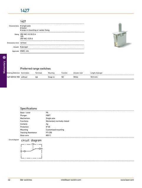
Momentary<br />
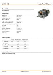
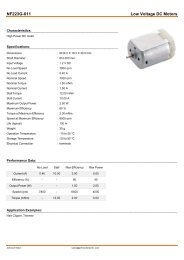
<strong>1427</strong><br />
Characteristics � single pole<br />
� faston<br />
� snap-in mounting or center-fixing<br />
Rating 250 VAC, 0,2 [0,2] A<br />
1E5<br />
250 VAC, 0.25 A<br />
Dimensions (mm) various<br />
Actuator � plunger<br />
Approvals ENEC, cUL<br />
<strong>Preferred</strong> <strong>range</strong> <strong>switches</strong><br />
Ordering Reference Illumination Terminals Mounting Function Actuator color Length of plunger<br />
<strong>1427</strong>-839.02 1551 without tab Snap-in NC White 18,0 mm<br />
Circuit diagram<br />
<strong>1427</strong><br />
<strong>Specifications</strong><br />
Base / cover PA<br />
Plunger PBPT<br />
Mechanism Single pole<br />
Functions Momentary normally closed<br />
Contacts Ag<br />
Protection IP 00<br />
Mounting Customised mounting<br />
Tracking Resistance PTI 250<br />
Glow-wire 850°C<br />
42 Bär <strong>switches</strong> info@baer-switch.com<br />
www.baer.com
Dimensions<br />
<strong>1427</strong><br />
Operating Characteristics<br />
<strong>1427</strong> 250 VAC, 0,2 [0,2] A<br />
100.000 cycles T55<br />
Standard Range<br />
Ordering Reference Illumination Terminals Mounting Function Actuator color Length of plunger<br />
<strong>1427</strong>-022.02 1511 Without tab Center-fixing NC White 17,0 mm<br />
<strong>1427</strong>-132.02 1551 Without tab Snap-in NC Black 12,2 mm<br />
Bär <strong>switches</strong> info@baer-switch.com<br />
width<br />
www.baer-switch.com 43<br />
Momentary
Momentary<br />
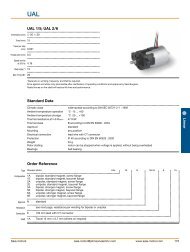
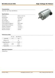
1430<br />
Characteristics � single pole<br />
� faston<br />
� snap-in mounting<br />
Rating 250 VAC, 0,2 [0,2] A<br />
5E4<br />
Dimensions (mm) various<br />
Actuator � lever<br />
Approvals ENEC<br />
<strong>Preferred</strong> <strong>range</strong> <strong>switches</strong><br />
<strong>Preferred</strong> Illumination Terminals Mounting Function Lever color<br />
1430-045.02 1551 Without tab 4,8 mm Snap-in NC White<br />
Circuit diagram<br />
1430<br />
<strong>Specifications</strong><br />
Base / cover PA<br />
Plunger PBPT<br />
Mechanism Single pole<br />
Functions Momentary normally closed<br />
Contacts Ag<br />
Protection IP 00<br />
Mounting Customised mounting<br />
Tracking Resistance PTI 250<br />
Glow-wire 850°C<br />
44 Bär <strong>switches</strong> info@baer-switch.com<br />
www.baer.com
Dimensions<br />
1430<br />
Operating Characteristics<br />
1430 250 VAC, 0,2 (0,2) [0,2] A<br />
50.000 cycles T55<br />
Standard Range<br />
width<br />
Ordering Reference Illumination Terminals Mounting Function Lever color<br />
1430-042.02 1651 Without tab 6,3 mm Snap-in NC White<br />
Bär <strong>switches</strong> info@baer-switch.com<br />
www.baer-switch.com 45<br />
Momentary
Snap-action<br />
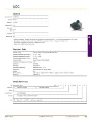
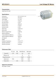
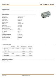
XKA<br />
XKA<br />
Characteristics � long overtravel<br />
� snap-action CO<br />
� snap-in mounting<br />
� type of protection according to IEC 60079-15.1 : 1987<br />
Rating 250 VAC, 1 (1) A<br />
5E4, T85<br />
Dimensions (mm) 28 � 20 � 15<br />
Actuator � plain lever<br />
� round levers<br />
Approvals UL, CSA, ENEC<br />
<strong>Preferred</strong> Range<br />
Ordering Reference Actuating Force Sealing Operating pos. Terminal Circuit Actuator Contacts <strong>Electric</strong>al rating<br />
(N) (mm)<br />
XKA304A1AAJ11 0,65 IP40 15,1 ± 1,6 tab CO Straight lever Ag/AgNi 250 VAC, 1 A<br />
XKA304A1AAJ21 0,62 IP40 14,9 ± 1,6 tab CO Straight lever Ag/AgNi 250 VAC, 1 A<br />
48 Bär <strong>switches</strong> info@baer-switch.com<br />
www.baer.com
Circuit diagram<br />
Dimensions<br />
XKA<br />
<strong>Specifications</strong><br />
Housing PA<br />
Plunger PA<br />
Mechanism Snap-action system with stainless steel tension spring<br />
Functions Change-over<br />
Contacts Ag<br />
Terminals tab<br />
Temperature <strong>range</strong> ºC 85°C<br />
Mechanical life 3 ·10 5 cycles minimum<br />
Protection Enclosure IP 40<br />
Mounting Snap-in fixing<br />
Contact carrier Brass<br />
Tracking resistance PTI 175<br />
Glow-wire 850°C<br />
� � �<br />
Recommended maximum electrical ratings<br />
Voltage Resistive load Motor load<br />
VAC (A) (A)<br />
250 1 1<br />
The breaking capacities in the tables refer to silver contacts. Gold-plated contacts are intendend for use in signal circuits where the energy<br />
being switched is at the milliwatt level. Power being switched must be limited in order to avoid overheating and possible dispersal of the<br />
gold from the contact area.<br />
Bär <strong>switches</strong> info@baer-switch.com<br />
www.baer-switch.com 49<br />
Snap-action
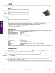
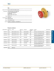
XP<br />
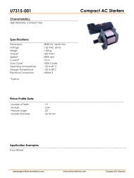
XP<br />
Characteristics ■ forced double break switching<br />
■ positive-action force break option<br />
■ > 3 mm contact gap at full travel option<br />
■ faston terminals<br />
Rating 400 VAC, 16 A<br />
Dimensions (mm) 30 • 32 • 12<br />
Actuator ■ plain plunger<br />
■ mushroom plunger<br />
■ plunger with external spring (for increased reset security)<br />
Approvals ENEC, UL, CSA<br />
Burgess <strong>switches</strong><br />
<strong>Preferred</strong> Range<br />
Ordering Actuating Force Operating pos. Terminal Circuit Actuator Contacts <strong>Electric</strong>al rating<br />
Reference (N) (ozf) (mm) (in)<br />
XP2Z11 3,0 10,0 14,9 0,587 Faston CO Straight plunger Ag nickel Up to 400 VAC, 16 A<br />
XP42Z11 1,8 6,2 14,9 0,587 Faston NC Straight plunger Ag nickel Up to 400 VAC, 16 A<br />
XP52Z11 3,0 10,0 13,0 0,511 Faston NO Straight plunger Ag nickel Up to 400 VAC, 16 A<br />
XP52E1Z11 6,5 23,3 13,0 0,511 Faston NO Mushroom plunger, reset Ag nickel Up to 400 VAC, 16 A<br />
XP2E2Z11 3,0 10,0 14,9 0,587 Faston CO Mushroom plunger, reset Ag nickel Up to 400 VAC, 16 A<br />
burgess-switch@johnsonelectric.om<br />
www.burgess-switch.com<br />
65<br />
Forced break
Forced break<br />
Circuit diagram<br />
Dimensions<br />
XP<br />
<strong>Specifications</strong><br />
Housing Glass fibre reinforced nylon<br />
Plunger Glass fibre reinforced nylon<br />
Mechanism Change-over, normally open, normally closed<br />
Contacts Silver<br />
Terminals 6.3 mm (0.25 in) faston brass<br />
Temperature <strong>range</strong> °C –20°C to +140°C<br />
Mechanical life 10 7 cycles minimum (impact free actuation)<br />
Protection IP40 (enclosure)<br />
Mounting Screw mounting<br />
Actuators Straight or mushroom plunger<br />
Special features Optional reset spring for increased reset security<br />
1<br />
3<br />
1<br />
3<br />
4<br />
2<br />
1 125 VAC - - ⁄4 HP (0.45 pf) UL 1 3 1054 4 2 - Horsepower- 6,000 operations<br />
66 Burgess <strong>switches</strong> burgess-switch@johnsonelectric.om<br />
www.burgess-switch.com<br />
2 MOUNTING HOLES<br />
É”4.3Å}0.05 [0.17]<br />
NORMALLY<br />
OPEN<br />
NORMALLY<br />
CLOSED<br />
2 MOUNTING HOLES<br />
É”4.3Å}0.05 [0.17]<br />
32.0<br />
[1.26]<br />
30.3<br />
[1.19]<br />
6.0<br />
[0.24]<br />
[0.1]<br />
22.0±0.1<br />
[0.87]<br />
R2.5<br />
[0.1]<br />
R2.5<br />
TOTAL TRAVEL<br />
POSITION<br />
OPERATING<br />
POSITION<br />
FREE<br />
POSITION<br />
22.0±0.1<br />
[0.87]<br />
30.0<br />
[1.18]<br />
6.0<br />
[0.24]<br />
13.0±0.2<br />
[0.51]<br />
ɔ4.0<br />
[0.16]<br />
TOTAL TRAVEL<br />
POSITION<br />
OPERATING<br />
POSITION<br />
FREE<br />
POSITION<br />
6.8<br />
6.3 X 0.8<br />
[0.25 X 0.03]<br />
2 MOUNTING HOLES<br />
É”4.3Å}0.05 [0.17]<br />
13.0±0.2<br />
2 MOUNTING HOLES<br />
Voltage Resistive load Inductive load Horsepower É”4.3Å}0.05 [0.17] Approval<br />
22.0±0.1<br />
[0.87]<br />
[0.51]<br />
10.0<br />
[0.39]<br />
12.0<br />
[0.47]<br />
ɔ4.0<br />
Recommended maximum electrical ratings<br />
(max) (A)<br />
2<br />
4<br />
[0.27]<br />
[0.16]<br />
32.0<br />
[1.26]<br />
30.3<br />
[1.19]<br />
6.0<br />
[0.24]<br />
TOTAL TRAVEL<br />
POSITION<br />
OPERATING<br />
POSITION<br />
FREE<br />
POSITION<br />
13.0±0.2<br />
[0.51]<br />
ɔ8.0<br />
[0.31]<br />
22.0±0.1<br />
[0.87]<br />
30.0<br />
[1.18]<br />
6.0<br />
[0.24]<br />
TOTAL TRAVEL<br />
POSITION<br />
OPERATING<br />
POSITION<br />
FREE<br />
POSITION<br />
6.8<br />
[0.27]<br />
6.3 X 0.8<br />
[0.25 X 0.03]<br />
13.0±0.2<br />
2 MOUNTING HOLES<br />
É”4.3Å}0.05 [0.17]<br />
[0.51]<br />
ɔ8.0<br />
[0.31]<br />
250 VAC 16 (0.75 pf) - - UL 1054/CSA 22.2 No. 55 - 6,000 operations<br />
250 VAC - - 1 ⁄4 HP (0.45 pf) UL 1054 - Horsepower- 6,000 operations<br />
250 VAC 16 6 - EN.60158-1 T85 (°C) 50,0000 operations<br />
400 VAC 16 4 - EN.60158-1 T140 (°C) 10,0000 operations<br />
XP2Z11 3/4 FULL SIZE<br />
10.0<br />
[0.39]<br />
12.0<br />
[0.47]<br />
XP2E1Z11 3/4 FULL SIZE<br />
0-15 VDC 10 - - General rating - 50,000 operations<br />
15-30 VDC 7 - - General rating - 50,000 operations<br />
[0.1]<br />
22.0±0.1<br />
[0.87]<br />
R2.5<br />
TOTAL TRAVEL<br />
POSITION<br />
OPERATING<br />
POSITION<br />
FREE<br />
POSITION<br />
13.0±0.2<br />
[0.51]<br />
ɔ4.0<br />
[0.16]<br />
2 MOUNTING HOLES<br />
É”4.3Å}0.05 [0.17]<br />
32.0<br />
[1.26]<br />
30.3<br />
[1.19]<br />
6.0<br />
[0.24]<br />
1 3<br />
22.0±0.1<br />
[0.87]<br />
30.0<br />
[1.18]<br />
4 2<br />
6.0<br />
[0.24]<br />
2 MOUNTING HOLES<br />
É”4.3Å}0.05 [0.17]<br />
TOTAL TRAVEL<br />
POSITION<br />
OPERATING<br />
POSITION<br />
FREE<br />
POSITION<br />
6.8<br />
[0.27]<br />
6.3 X 0.8<br />
[0.25 X 0.03]<br />
22.0±0.1<br />
[0.87]<br />
13.0±0.2<br />
[0.51]<br />
ɔ6.0<br />
[0.24]<br />
10.0<br />
[0.39]<br />
12.0<br />
[0.47]<br />
XP2E2Z11 3/4 FULL SIZE<br />
TOTAL TRAVEL<br />
POSITION<br />
OPERATING<br />
POSITION<br />
FREE
XP<br />
Burgess <strong>switches</strong><br />
Operating Characteristics<br />
Actuating Release Free Operating Total Travel Over<br />
Actuator Reference Force Force Position Position Position travel<br />
Maximum Minimum Maximum Maximum<br />
(N) (ozf) (N) (ozf) (mm) (in) (mm) (in) (mm) (in) (mm) (in)<br />
Straight plunger XP2Z11 3,00 10,0 5,5 19,7 15,3 0,602 14,9 ± 0.4 0,587 ± 0.016 8,0 0,315 4,5 0,177<br />
XP42Z11 1,75 6,20 5,5 19,7 15,3 0,602 14,9 ± 0.4 0,587 ± 0.016 8,0 0,315 6,5 0,256<br />
XP52Z11 3,00 10,0 5,5 19,7 16,6 0,653 13,0 ± 0.4 0,511 ± 0.016 8,0 0,315 4,5 0,177<br />
Basic type XP Momentary<br />
XPS Positive action forced break (normally closed only)<br />
Circuit 2 Change-over<br />
4 Normally closed<br />
5 Normally open<br />
Terminals 2 Faston 6,3 • 0,8<br />
Full overtravel Position<br />
Ordering Reference<br />
Actuators No symbol, straight plunger<br />
E1 Mushroom plunger with reset spring<br />
E2 Mushroom plunger<br />
Approvals Z11 UL, cUL, CSA and ENEC<br />
Operating Position<br />
Rest Position<br />
Mushroom XP2E1Z11 6,5 23,3 9,0 32,3 15,3 0,602 14,9 ± 0.4 0,587 ± 0.016 10,5 0,413 2,1 0,082<br />
plunger with XP42E1Z11 3,75 13,4 9,0 32,3 15,3 0,602 14,9 ± 0.4 0,587 ± 0.016 10,5 0,413 4,0 0,157<br />
reset spring XP52E1Z11 6,5 23,3 9,0 32,3 16,6 0,653 13,0 ± 0.4 0,511 ± 0.016 10,5 0,413 2,1 0,082<br />
Mushroom plunger XP2E2Z11 3,0 10,0 5,5 19,7 15,3 0,602 14,9 ± 0.4 0,587 ± 0.016 8,6 0,339 4,0 0,157<br />
burgess-switch@johnsonelectric.om<br />
Example: XP 2 2 E1 Z11<br />
www.burgess-switch.com<br />
67<br />
Forced break
Forced break<br />
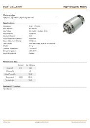
XT<br />
XT<br />
Characteristics ■ 8 mm contact gap 8 mm creepage and clearance distances<br />
■ forced double break contacts<br />
Rating 400 VAC, 16,5 A max.<br />
Dimensions (mm) 30 • 32 • 12<br />
Actuator ■ shrouded plunger<br />
■ optional key<br />
■ plain plunger<br />
Approvals UL, cUL, CSA, ENEC<br />
<strong>Preferred</strong> Range<br />
Ordering Actuating Force Operating pos. Terminal Circuit Actuator Contacts <strong>Electric</strong>al rating<br />
Reference (N) (ozf) (mm) (in)<br />
XTD22AZ1 3,8 13,6 13,0 0,511 Faston NO Plunger Ag nickel Up to 400 VAC, 16.5 A<br />
Circuit diagram<br />
Dimensions<br />
<strong>Specifications</strong><br />
Housing Glass fibre reinforced polyester<br />
Plunger Glass fibre reinforced polyester<br />
Mechanism Normally open<br />
Contacts Silver nickel<br />
Terminals 6.3 mm (0.25 in) faston - brass<br />
Temperature <strong>range</strong> °C –20°C to +85°C<br />
Mechanical life 10 6 cycles minimum (impact free actuation)<br />
Protection IP40 (enclosure)<br />
Mounting Snap-on or screw mounting<br />
Actuator Plunger (can be held depressed for maintenance with optional key shrouded option only)<br />
Accessories Maintenance key N41784 and multiplug housing XTMHSG<br />
68 Burgess <strong>switches</strong> burgess-switch@johnsonelectric.om<br />
www.burgess-switch.com
XT<br />
Basic type XTD<br />
Burgess <strong>switches</strong><br />
Recommended maximum electrical ratings<br />
Voltage Load Inductive load Horsepower Approval<br />
(max) (A)<br />
125 VAC 15.5 (0.75 pf) - - UL 1054/CSA 22.2 No. 55 - 100,000 operations<br />
250 VAC 15.5 (0.75 pf) - - UL 1054/CSA 22.2 No. 55 - 100,000 operations<br />
125 VAC - - 1 ⁄2 HP (0.45 pf) UL 1054 - Horsepower- 100,000 operations<br />
250 VAC - - 1 ⁄2 HP (0.45 pf) UL 1054 - Horsepower- 100,000 operations<br />
125 VAC - - 1 1 ⁄2 HP (0.45 pf) UL 1054 - Horsepower- 100,000 operations<br />
250 VAC - - 1 1 ⁄2 HP (0.45 pf) UL 1054 - Horsepower- 100,000 operations<br />
30 VAC 0,5 - - EN.60158-1 T85 (°C) 50,0000 operations<br />
400 VAC 16,5 8 - EN.60158-1 T85 (°C) 50,0000 operations<br />
30 VDC 0,5 - - UL 1054/CSA 22.2 No. 55 - 6,000 operations<br />
Operating Characteristics<br />
Actuating Release Free Operating Total Travel Over<br />
Actuator Reference Force Force Position Position Position travel<br />
Maximum Minimum Maximum Maximum<br />
(N) (ozf) (N) (ozf) (mm) (in) (mm) (in) (mm) (in)<br />
Plunger XTD22AZ1 3,8 13,600 5,8 20,8 18,0 0,708 13,0 ± 0.4 0,511 ± 0.016 10,0 0,394 3,0 0,118<br />
( ± 0.5) ( ± 3.5) (main contact)<br />
Ordering Reference<br />
Terminals 22 6.3 • 0.8 mm faston terminals<br />
A 100 k operations at 15:5 A 250 VAC, UL114 478<br />
Form – Without identification: snap-on mounting with shroud<br />
J Snap-on mounting without shroud<br />
P Without shroud, without snap-on mounting<br />
K<br />
Approvals Z1 UL, cUL, CSA and ENEC<br />
burgess-switch@johnsonelectric.om<br />
12,6 0,496<br />
(low voltage contact)<br />
Example: XTD 22 J Z1<br />
www.burgess-switch.com<br />
69<br />
Forced break