INSTALLATION SERVICING & USER INSTRUCTIONS
installation, servicing & user instructions - Burley
installation, servicing & user instructions - Burley
- No tags were found...

You also want an ePaper? Increase the reach of your titles
YUMPU automatically turns print PDFs into web optimized ePapers that Google loves.
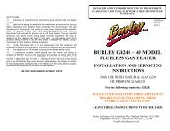
BURLEY G4121 mk2<br />
FLUELESS GAS HEATER<br />
<strong>INSTALLATION</strong>, <strong>SERVICING</strong><br />
& <strong>USER</strong> <strong>INSTRUCTIONS</strong><br />
FOR USE IN THE COUNTRIES STATED ON THE DATA PLATE AND CARTON<br />
WITH NATURAL GAS G20<br />
OR LPG PROPANE GAS G31<br />
(REFER TO RATING LABEL)<br />
For the following countries: GB, IE<br />
EVEN IF YOU HAVE FITTED THESE FIRES BEFORE,<br />
PLEASE FOLLOW THESE <strong>INSTRUCTIONS</strong> STEP BY STEP.<br />
Legislation and regulations do change over time!<br />
LEAVE THESE <strong>INSTRUCTIONS</strong> WITH THE <strong>USER</strong><br />
TO OBTAIN YOUR FIRST YEAR GUARANTEE, THE INSTALLER AND CUSTOMER<br />
MUST FILL IN THE SEPARATE GUARANTEE AND RETURN IT TO<br />
BURLEY WITIHIN 7 DAYS OF FITTING.<br />
A FREE SECOND YEAR GUARANTEE IS OFFERED SUBJECT TO THE FIRE BEING SERVICED<br />
BY A CORGI ENGINEER DURING THE FIRST YEAR OF OWNERSHIP.<br />
PROOF OF <strong>SERVICING</strong> MUST BE RETAINED<br />
FAILURE TO HAVE THIS APPLIANCE FITTED BY A CORGI REGISTERED<br />
FITTER INVALIDATES THE WARRANTY<br />
Burley Appliances Ltd,<br />
Lands End Way, Oakham, Rutland, LE15 6RB<br />
Telephone: +44 (0)1572 756956 Fax: +44 (0)1572 724390<br />
e-mail: info@burley.co.uk web: www.burley.co.uk<br />
G4121InstUser<br />
G20/31<br />
Issue JAN08 – v.1
INTRODUCTION<br />
Thank you for choosing this burley product. All of our products carry a CE mark which is awarded by<br />
an independent test house (notified body) and shows the fires have been type tested to meet the<br />
essential requirements of the European Gas Appliance Directive and the appropriate British<br />
Standards.<br />
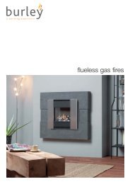
This is a highly efficient Flueless Inset Live Fuel Effect Appliance. The burner system is very clean<br />
burning and a catalyst cleans the combustion products even further.<br />
A thermostat in the burner control system adjusts heat output to maintain a room temperature,<br />
which can easily be set by the user. The appliance is operated via a battery powered remote control<br />
system. There is also a separate control to adjust the flame effect as required. Please demonstrate<br />
its operation to the customer before leaving.<br />
An oxygen depletion sensing pilot light is also fitted and will sense any significant oxygen depletion<br />
in the room and shut the fire down safely.<br />
1. APPLIANCE DATA<br />
Refer to the appliance data badge (affixed behind controls door) ENSURE THAT THE LOCAL<br />
CONDITIONS OF USE CORRESPOND TO THE INFORMATION ON THE DATA BADGE.<br />
Natural Gas G20 LPG (Propane) G31<br />
Category I2H I3P<br />
Supply Pressure 20mBar 37mBar<br />
Inlet Pressure 20mBar* 37mBar*<br />
Burner Pressure (High) 9.4mBar 35.5mBar<br />
(Low) 2.2mBar 8mBar<br />
Heat Input (Net) (High) 3.5kW 3.5kW (250g/h)<br />
(Low) 1.7kW 1.7kW (120g/h)<br />
Inlet Connection 8mm Compression 8mm Compression<br />
Injector stereo 185 stereo 95<br />
*The inlet pressure must be within +/- 1mBar of specification with all gas appliances in the house<br />
switched on and also with just the Burley heater operating. If outside of this tolerance the fault is<br />
most likely to be in the installation pipe work or service governor at the meter. If the problem is the<br />
meter governor, this is the property of the gas service provider (such as Transco / National Grid<br />
0800 111999 or Bord Gais) and they should be called to rectify this. The fire will not operate<br />
correctly if the pressures are incorrect.<br />
2. UNPACKING THE APPLIANCE<br />
2.1 Carefully examine the carton for damage before unpacking. If it is obviously damaged,<br />
consult the supplier as to whether to proceed with the installation.<br />
2.2 Make sure the carton is stood upright and open the top. Remove the cardboard top fitting<br />
and place to one side; this box can be used as a hearth protector when installing the fire.<br />
2.3 Remove the fittings boxes contained within and open them and check the condition of the<br />
contents. Remove the fire and examine its general condition, paying particular attention to<br />
the frame, the glass front and fire box flanges.<br />
2.4 If satisfied by the general condition, place the decorative components to one side and<br />
proceed with the installation. If in any doubt, seek advice from the supplier. Read these<br />
instructions fully before proceeding even if you have fitted this model before.<br />
2
3. GENERAL REQUIREMENTS<br />
3.1 Gas appliances must be installed in accordance with the rules in force. In the UK it is the law<br />
that all gas appliances must be installed by a CORGI registered installer, in accordance with<br />
the Gas Safety (Installation and Use) regulations (as amended). The installation must also be<br />
in accordance with the relevant parts of local and national building regulations and in<br />
accordance with BS5871 pt4 except where Burley instruction state differently. For the<br />
Republic of Ireland, reference should be made to IS813 and ICP3 and any guidance notes<br />
from Bord Gais. Failure to have the fire fitted by a qualified person nullifies ALL guarantees.<br />
3.2 The space to be heated must have a wall vent of at least 100cm² of ventilation and an<br />
openable window or patio door. The vent must be positioned at least 1 metre away from<br />
the appliance. A vent may have been supplied with the appliance and this is the preferred<br />
type although it is possible to use alternatives.<br />
3.3 In the Republic of Ireland two vents of not less than 60cm² each, one not less than 1.6m<br />
above the other, must be installed in the room.<br />
3.4 When providing ventilator openings consideration must be given to the avoidance of<br />
locations where discomfort from draughts may cause the user to block the openings.<br />
Similarly the possibility of curtains or furniture blocking ventilation openings must be<br />
considered. Floor vents, closable window vents or chimneys are not suitable means of<br />
ventilation.<br />
3.5 Working surfaces include the air outlet grille.<br />
3.6 The heater must not be used in a room area of less than 40m3 in volume. To convert cubic<br />
feet (ft³) to cubic metre (m³) divide the room volume in cubic feet by 35.3. Adjoining spaces,<br />
not separated by a door may be combined.<br />
3.7 The heater must not be used on or against a combustible surface.<br />
3.8 No furniture, soft furnishings, decorations, wall coverings or curtains must be within 1 metre<br />
of the appliance and its convection outlets.<br />
3.9 The heater must not be installed in high rise flats or basements.<br />
3.10 Do not install this appliance in:<br />
a) A bathroom, shower room or in a room used or intended to be used as sleeping<br />
accommodation. Sleeping areas must be separated from the appliance by a door.<br />
b) In a cupboard or compartment within such a room; or<br />
c) In a cupboard, compartment or space adjacent to such a room if there is an air vent from<br />
the cupboard, compartment or space into such a room.<br />
3.11 When the heater is not to be used for a time, ensure the gas control or adjacent isolators<br />
are turned off.<br />
3.12 Using this appliance as a sole heat source can lead to condensation problems in periods of<br />
cold weather and heavy use. Always ensure that the room has a background heat source<br />
such as central heating or storage heaters.<br />
3.13 The fire must not be run with its door open or with cracked, incorrectly fitted or missing<br />
glass.<br />
3.14 The glass door acts as a guard on the appliance to prevent risk of fire or injury from burns<br />
and no part of it may be permanently removed. It does not give full protection for young<br />
children, the elderly or infirm. Parts of the appliance get hot, an additional guard to BS6539<br />
or BS6778 must be used in the presence of children, the elderly and infirm.<br />
3.15 This is not a drying appliance. Do not place clothing or other articles, on or against it.<br />
3.16 On no account must air inlets under the stove or outlet grills (see diagram below) be<br />
obstructed.<br />
3.17 Do not store or use flammable substances on or near the heater.<br />
3.18 Do not spray aerosols on or near the heater when it is working.<br />
3
3.19 Do not use whilst painting & decorating, or in newly decorated rooms as the residues can<br />
lead to unpleasant smells from the appliance. Always cover or have the appliance removed<br />
when decorating.<br />
3.20 The heater must not be used in rooms where the atmosphere is likely to contain water or<br />
chemical vapours which may adversely affect the appliance or its finish.<br />
3.21 If any material, such as plastic, melts onto the surface of the glass, turn the heater off and<br />
allow it to cool. Do not remove the material when hot. A proprietary ceramic hob cleaner<br />
such as ‘hob brite’ can be used to clean the glass. Only clean the appliance when cold.<br />
4. WARNINGS<br />
4.1 Read the instructions before using this appliance.<br />
4.2 This appliance requires installation by a competent qualified person.<br />
4.3 Use only in a correctly sized and ventilated area.<br />
4.4 Once the coals have been positioned in accordance with the installation instructions, they<br />
must not be moved except for servicing.<br />
4.5 The surfaces of the appliance become very hot during use.<br />
4.6 Before cleaning or maintenance switch fire OFF and allow to cool.<br />
4.7 Any purpose provided ventilation should be checked regularly to ensure it is free from<br />
obstruction.<br />
Overall Dimensions<br />
540<br />
330<br />
Outlet grille<br />
DO NOT COVER<br />
620<br />
Air inlets<br />
DO NOT BLOCK<br />
5. Hearths, floor protection and carpets<br />
5.1 This appliance does not need a hearth and can be used on wooden, laminate floors and noncombustible<br />
surfaces. It must not be placed directly onto carpets or rugs. Where the floor is<br />
carpeted, the carpet must finish 100mm clear of the appliance legs and be fully removed<br />
underneath. Loose rugs should be kept well away from the appliance (warn the customer of this).<br />
5.2 Standing the appliance directly on a floor can lead to discolouration and / or drying out.<br />
5.3 When a hearth is used, the top surface can be wood but be aware that heat can discolour certain<br />
finishes over a period of time and can dry out poorly seasoned wood causing splitting. The hearth<br />
should be 100mm larger than the appliance all round and minimum 12mm thick. Carpets can come<br />
to the edge of the hearth.<br />
4
6. Clearance to Walls<br />
Rear Clearance - The rear of the appliance can be installed directly against a non combustible wall. A<br />
distance of 50mm should be allowed to walls with wooden cladding, wallpaper, or finishes likely to be<br />
affected by heat.<br />
Side Clearance - The sides of the appliance can be installed with 25mm of side clearance to non combustible<br />
materials. Combustible material such as wood may be fitted to within 100mm of the sides of the firebox<br />
provided it protrudes no further forward than 100mm.<br />
Top Clearance - The heat from the appliance is concentrated towards the front edge directly above the<br />
combustion products outlet. The clearances stated relate to a distance from the back edge of the stove.<br />
A non combustible shelf may be fitted to within 50mm of the top edge of the fire.<br />
Maximum depth of shelf 100mm 150mm 200mm<br />
Minimum distance from 200mm 250mm 300mm<br />
Top of fire to underside of shelf<br />
These distances should be doubled if the shelf is above the outlet grille.<br />
The fireplace and ALL materials including paints or lacquers must be rated for a minimum<br />
constant temperature of 150°C. Any hearth or back panel not meeting the above clearance<br />
dimensions must be made from a non-combustible material such as marble or slate, although<br />
‘lightweight’ and tiled surrounds can be used provided they have a minimum heat rating of<br />
150°C.<br />
7. Gas Supply<br />
The gas supply should be installed in accordance with all regulations in force. Consideration should be given<br />
to the routing to conceal from view and avoid potential damage. Pipes through walls should be sleeved. The<br />
gas connection is 8mm compression and should be made in semi-rigid tubing such as copper pipe. Before<br />
working on pipework plug open ends. A servicing isolator is supplied with the appliance and this should be<br />
used to permit disconnection for servicing etc.<br />
All gas work should be undertaken by a competent person, see General Requirements.<br />
8. Siting the Appliance<br />
8.1 If the appliance is to be in or in front of an open fireplace, the chimney or flue MUST be blocked off<br />
to prevent the draw from disrupting the flame pattern of the fire, which can lead to poor<br />
combustion, or sooting. Extractor fans must be sited at least 2m from the appliance.<br />
8.2 Check the room has sufficient volume and ventilation, if these requirements cannot be met then the<br />
appliance should not be installed. Consideration should be given to the requirements of other<br />
appliances working in the same room space. If other flueless appliances such as cookers are in the<br />
same room then consideration should be given to the combined room size requirement.<br />
8.3 Check the room has a background heat source such as central heating radiators, storage heaters etc.<br />
8.4 Check the appliance data plate details are correct for the kind of gas used and the country of<br />
installation.<br />
8.5 Carry out any building works such as ingle-nooks, hearths and recesses. If no hearth is being used,<br />
remove any carpets to required clearance. Lay in the gas supply and leave a tail to connect to.<br />
8.6 Position the appliance and ensure it is stable and unlikely to move in normal use. Some hearths can<br />
be slippery and it is best to fix the appliance by removing the plugs in the plastic feet and screwing<br />
down. Care should be taken to ensure correct clearances around the stove.<br />
8.7 Before connecting any pipes to the appliance, fully purge pipes of any debris or swarf etc.<br />
8.8 Attach the gas connection to the stove and carry out a leak test in an approved manner.<br />
8.9 Unclip the thermostat from the back of the stove and by carefully extending the capillary tube locate<br />
it in a place where it will sense room temperature. This is particularly important if the stove is fitted<br />
in an ingle nook where the thermostat could give a misleading shut down unless it is relocated to a<br />
cool location. We recommend clipping to the rear of the appliance.<br />
5
9. Laying the Logs<br />
Opening the hinged door on the appliance, which is secured by a 10mm nut, gains access to the coals. On no<br />
account should the appliance be operated whilst the door is open except for brief periods during<br />
maintenance. Do not lay the log in any way other than that shown.<br />
LOG LAYOUT (NATURAL GAS)<br />
The base and front logs are fixed in position and<br />
should only need removing for servicing. The base<br />
log locates onto the burner and the front log is<br />
pushed to the extreme left hand side. Take the 2<br />
loose logs* and position them as shown onto the cut<br />
outs on the base log, taking care to locate them<br />
correctly to ensure clean combustion. No additional<br />
logs should be added to the fire.<br />
Note the pilot position on the right hand side of the<br />
burner.<br />
LOG LAYOUT (LPG PROPANE)<br />
The base and front logs are fitted similar to the<br />
Natural Gas fire. The base log locates onto the<br />
burner and the front log is pushed to the extreme<br />
left hand side as shown. Take the 2 loose logs* and<br />
position them as shown onto the cut outs on the<br />
base log, taking care to locate them correctly to<br />
ensure clean combustion. No additional logs should<br />
be added to the fire.<br />
Note the pilot position on the right hand side of the<br />
burner.<br />
*Note – The 2 top logs may be supplied glued in<br />
position and should not be removed or repositioned. If they become detached then they can be fitted as<br />
per the diagram but must on no account be discarded or fitted in any other way.<br />
Always secure the door closed after laying the fuel effects.<br />
Do not attempt to use any unit with broken or damaged glass.<br />
Do not use the fire with broken logs.<br />
Do not add any additional fuel elements to the fire.<br />
Do not use similar looking parts from other appliances, use only genuine spare parts.<br />
Do not use the appliance for burning waste.<br />
10. Commissioning the Appliance<br />
If the pipes have not been purged of debris do it before lighting the appliance. Failure to do so will result<br />
in blockages within the burner and pilot.<br />
6
Burley Appliances is the only company to bench run and thoroughly test every single gas fire it produces.<br />
Burley is in the unique position of knowing that every appliance that leaves the factory is in perfect<br />
working order.<br />
The installer should measure the inlet pressure with the appliance running on high and ensure it is to<br />
specification.<br />
Attach a manometer to the inlet test point and ensure there is a pressure of 20mb (+/- 1mb) for natural gas<br />
appliances or 37mB for propane appliances.<br />
Now turn on every other gas appliance in the house and re-check the pressure. The pressure must still be<br />
within the tolerance of +/- 1mb.<br />
Turn off all other gas appliances and turn the fire down to pilot only, the pressure must still be within the<br />
tolerance of +/- 1mb.<br />
If it is not TRANSCO or BORD GAIS must be called to adjust the regulator to the house before the fire can be<br />
commissioned further.<br />
Any large pressure fluctuation indicates pipework or governor problems and should be rectified. Instruct the<br />
customer on the operation of the appliance and leave all instructions with them.<br />
The fires are factory set and no adjustments should be made in the field.<br />
11. Lighting the Heater<br />
To light the fire, press the left hand (red) control knob for<br />
several seconds then turn anticlockwise to the ignition<br />
position. A click will be heard and the pilot (under right side<br />
of fuel bed) should light. If it does not light, repeat the<br />
operation a few times. Continue to hold knob for 15 – 20<br />
sec's to establish the pilot and then release. If pilot fails to<br />
establish, turn off, wait 1 minute then repeat lighting<br />
procedure. Rotate the control knob to high flame to light<br />
then back to the desired flame position. If no gas comes Control Knob<br />
through rotate the right knob (thermostat) to a hotter room<br />
setting and the fire will light. To turn the fire off, rotate knob fully clockwise.<br />
12. Spark Failure<br />
H<br />
M<br />
L<br />
Thermostat<br />
The gap between the pilot electrode and the pilot should be 3.5 – 4.5mm and normally adjustment is not<br />
necessary. Check the fire lights at least 3 times out of 5 attempts. Visually check that the spark arcs across to<br />
the gas port on the pilot. The electrode is delicate but if necessary can be adjusted to set the spark. If the<br />
igniter fails a lighted taper can be inserted into the pilot area when attempting to light the pilot and this<br />
should help the fire to light.<br />
13. Thermostat<br />
A room temperature thermostat is attached to the back of the fire. For accurate monitoring of room<br />
temperature it is advised that the sensing bulb is removed from its clip and carefully moved to a cooler<br />
location up to 1 metre away, taking care not to break or pinch the capillary tube. If the fire is fitted in an<br />
ingle nook then the thermostat should be located in room air as leaving it under the fire will cause nuisance<br />
shut down.<br />
14. Fireguards<br />
The glass front on the appliance acts as a dress guard but does not provide full protection. An additional<br />
guard should always be fitted in the presence of young children, the elderly or the infirm.<br />
7
15. Oxygen Depletion Pilot System<br />
There is a highly sensitive oxygen depletion sensor designed into the pilot light. If any part is damaged the<br />
entire unit must be replaced using only genuine spare parts as similar looking parts from other appliances<br />
may well give inferior performance. If the fire repeatedly trips off in operation the oxygen depletion system<br />
may be operating and a qualified engineer should investigate this.<br />
16. Instructing the Customer<br />
The installer should instruct the customer on the operation of the appliance and handover all instruction<br />
leaflets.<br />
The customer must be made aware of the need for regular servicing of the appliance, this will normally be<br />
once a year.<br />
The customer should also be made aware that no rubbish should be thrown into the firebed and that<br />
purpose provided ventilation should be checked regularly.<br />
17. Servicing Instructions<br />
Before commencing any servicing, ensure that the gas is isolated and the appliance is cool.<br />
Cleaning – The casing should be wiped with a cloth dampened in soapy water. The glass may be cleaned<br />
with any non-abrasive cleaner such as ‘hob brite‘.<br />
The coals contain refractory fibre (RCF). Excessive exposure to these materials may cause temporary<br />
irritation to the eyes, skin and respiratory tract; consequently, it makes sense to take care when handling<br />
these parts to ensure that the release of dust is kept to a minimum. We recommend the use of a HEPA<br />
filtered vacuum to remove any dust and soot accumulated in the heater before and after working on it.<br />
When replacing these articles, they should not be broken up, but sealed in heavy duty polythene bags<br />
labelled RCF Waste’, which may be disposed of at a tipping site licensed for industrial waste. Protective<br />
clothing is not required, but normal hygiene rules of no smoking, eating or drinking in the work area should<br />
be followed.<br />
Controls – The system for monitoring the oxygen supply to the burner is not adjustable and must not be put<br />
out of operation. Should the oxypilot system need to be replaced, the original manufacturer’s parts must be<br />
used.<br />
Injectors – Only original manufacturer’s injectors must be used.<br />
The unit must be serviced at least once per year, preferably at the beginning of the heating season. All<br />
servicing must be carried out by a qualified service person. A combustion analysis check should be carried<br />
out using an analyser to BS7967 and sampling the entire width of the combustion product outlet. Ratio of<br />
CO/CO2 should be less than 0.002 within 30 minutes. (20ppm CO per 1% CO2) A reading of CO in the room<br />
centre should give a rise of less than 9ppm over ambient, peak reading.<br />
Light the fire using the method in the instructions and ensure that the pilot lights consistently and the pilot<br />
flame envelopes the thermocouple evenly, it is located at the front on the right-hand side.<br />
The pilot should hold in 6-10 seconds. Turn control to main burner, this should light smoothly within 10<br />
seconds. Ensure the valve gives adequate turn down and the thermostat bulb reduces the burner rate to off<br />
when heated.<br />
Locate thermostat bulb in a cool place off the appliance and preferably outside of any inglenooks, to ensure<br />
it is sensing room air temperature.<br />
Run the appliance for 10 minutes, ensuring burner flames settle evenly.<br />
The gas manifold pressures are factory pre-set using highly accurate equipment, and must not be altered.<br />
The catalyst is unlikely to need replacement during the life of the heater. The appliance should be inspected<br />
before use and at least annually by an authorised service person. More frequent cleaning may be required<br />
due to accumulation of lint and dust from carpeting etc.<br />
8
It is imperative that the control compartments, burners and circulating air passageways of the appliance be<br />
kept clean. Replacement parts are available from your local dealer.<br />
18. Accessories<br />
Using unapproved accessories could prove hazardous and will invalidate the warranty.<br />
BURLEY APPLIANCES ARE THE ONLY COMPANY TO BENCH RUN AND THOROUGHLY TEST EVERY<br />
SINGLE GAS FIRE IT PRODUCES. BURLEY ARE IN THE UNIQUE POSITION OF KNOWING THAT EVERY<br />
APPLIANCE LEAVES THE FACTORY IN PERFECT WORKING ORDER.<br />
Due to our policy of continual improvement and development the exact accuracy of descriptions<br />
and illustrations cannot be guaranteed.<br />
Due to our policy of continual improvement and development the exact accuracy of descriptions and illustrations can<br />
not be guaranteed.<br />
Burley Appliances are the only company to bench run and thoroughly test every single Flueless gas fire it produces.<br />
Burley is in the unique position of knowing that every appliance leaves the factory in perfect working order.<br />
9
User Instructions<br />
WARNINGS<br />
1. Read the instructions before using this appliance.<br />
2. This appliance requires installation and annual servicing by a CORGI registered installer.<br />
3. Use only in a correctly sized and ventilated area.<br />
4. Any purpose provided ventilation should be checked regularly to ensure it is free from<br />
obstruction.<br />
5. Once the logs have been positioned in accordance with the installation instructions; they must<br />
not be moved except for servicing.<br />
6. The surfaces of the appliance become very hot during use.<br />
7. If necessary the casing should be wiped with a cloth dampened in soapy water. Do not attempt<br />
to touch or wipe the fire whilst it is hot, doing so could result in damage to the paint finish and<br />
severe burns. Do not use any chemical cleaning agents or abrasive cleaners to clean the paint<br />
work of the fire as this may result in damage not covered by the guarantee. If the paint becomes<br />
damaged or worn, special touch up paint is available from our service department on 01572<br />
756956. Do not use any other type of paint.<br />
GENERAL REQUIREMENTS<br />
1. The heater is intended as a secondary heat source. Check that a primary source of heat (such as<br />
radiators) is present in the room. If insufficient primary heat is being used there may be a build up<br />
of condensation.<br />
2. The heater must not be used on or against a combustible surface. No furniture or curtains must<br />
be close to the appliance (or at risk of being blown close)<br />
3. In the event of gas leakage, the gas supply must be turned off and advice sought.<br />
4. The guard on the appliance is to prevent risk of fire or injury from burns and no part of it may be<br />
permanently<br />
removed. It does not give full protection for young children, the elderly or infirm. Parts of the<br />
appliance get hot,<br />
it is strongly recommended that an additional guard to BS6539 or BS6778 is used in the presence of<br />
children<br />
the elderly or infirm.<br />
5. This is not a drying appliance. Do not place clothing or other articles, on or against it.<br />
6. Do not store or use flammable substances on or near the heater.<br />
7. Do not spray aerosols on or near the heater.<br />
8. If any material, such as plastic, melts on the surface of the glass, turn the heater off and allow it<br />
cool. Do not remove the<br />
10
material when hot. A propriety non-abrasive ceramic hob cleaner such as ‘hob brite’ can be used to<br />
clean the glass.<br />
9. When the heater is not used for a time, ensure the gas control or adjacent isolator is turned off.<br />
The heater is not to be used for a time, ensure the gas control or adjacent isolator is turned off.<br />
10. The heater must not be used in rooms where the atmosphere is likely to contain water or<br />
chemical vapours, which may adversely affect the appliance or its finish.<br />
11. Do not use whilst painting & decorating, or in newly decorated rooms as the residue can lead to<br />
unpleasant smells from the appliance. Always cover or have the appliance removed when<br />
decorating.<br />
CONTROLS<br />
The fire is fitted with a gas valve and a thermostat. The thermostat automatically regulates the<br />
room temperature by turning the heat output (flames) up or down between high, half or pilot only.<br />
. The thermostat bulb must be resited to a cool area to measure the air temperature in the room<br />
more accurately. See installation instructions or consult the manufacturer.<br />
LIGHTING PROCEDURE<br />
Make sure there is no smell of gas<br />
1. Open the lower cover to reveal the gas control.<br />
2. There are 2 control knobs on the appliance. The left hand one (coloured red) controls On / Off<br />
and High / Low flame. The right hand one (coloured black) is the comfort level thermostat which<br />
turns the fire to pilot position once the desired temperature is reached. Some people prefer to<br />
retain a flame effect using the left hand knob to control its height whilst keeping the thermostat set<br />
on hot. Others prefer to use the fire purely as a heater in which case they will select a flame height<br />
then set the thermostat to a comfort level. In both cases if the room gets too hot, the thermostat<br />
will reduce the fire to pilot setting. If during use the pilot is alight but the main burner will not light,<br />
check the thermostat position and if necessary select a warmer setting.<br />
3. To light the fire, press the left hand (red) control knob for several seconds then turn<br />
anticlockwise to the ignition position. A click will be heard and the pilot (under right side of fuel<br />
bed) should light. If it does not repeat the operation a few times. Continue to hold knob for 15 – 20<br />
sec's to establish the pilot and then release. If pilot fails to establish, turn off, wait 1 minute then<br />
repeat the lighting procedure. Rotate the control knob to high flame to light then back to the<br />
desired flame position. If no gas comes through rotate the right knob (thermostat) to a hotter room<br />
setting and the fire will light.<br />
4. Control the fire by a combination of thermostat and / or flame setting to suit your mode of use<br />
5. To turn the fire off, rotate the left hand knob fully clockwise.<br />
NOTES<br />
1 The first time that the appliance is used, there will be some odour produced due to the<br />
newness of the materials. It is recommended that the unit is fired at maximum setting for<br />
several hours and the room is kept ventilated during this period. It is usual for flueless<br />
appliances to produce an initial odour after start up.<br />
2 When the pilot flame is alight, the unit may be controlled by turning the knob anywhere<br />
between 1 and 7. If the pilot flame should ever extinguish of its own accord, ventilate the<br />
room and allow a minimum of 5 minutes before relighting.<br />
3 Never attempt to relight the unit if there is a gas smell.<br />
11
4 If the unit continues to extinguish after a period of use, do not use it and seek the advice of<br />
your installer.<br />
5 Make sure that your installer has filled out your extended guarantee card and shown you how<br />
the fire operates.<br />
Cleaning the fuel effects<br />
The fuels can be accessed by opening the hinged door on the appliance which is secured by a 10mm<br />
nut. On no account should the appliance be operated whilst the door is open.<br />
Do not lay the logs in any way other than that shown in the Installation and Servicing Instructions.<br />
Do not use the fire with broken logs.<br />
Do not add any additional fuel elements to the fire.<br />
Do not use similar looking parts from other appliances, use only genuine spare parts.<br />
Do not use the appliance for burning waste.<br />
The fire must not be run with the door open or with cracked, incorrectly fitted or missing glass.<br />
On no account must air inlets under the stove or outlet grills (see diagram) be obstructed.<br />
540<br />
330<br />
Outlet grille<br />
DO NOT COVER<br />
620<br />
Air inlets<br />
DO NOT BLOCK<br />
TURN OFF PROCEDURE<br />
To extinguish the pilot, turn the valve to the OFF position. Note that if the gas supply fails at any<br />
time, the pilot will extinguish. Leave for one minute then carry out the lighting procedure to reignite.<br />
GENERAL<br />
1. To qualify for your free second year guarantee, you must fully complete and return the<br />
separate Guarantee Card. There are sections that your fitter must complete whilst he is fitting<br />
the fire. If the fully completed Guarantee Card is not returned within 7 days of fitting, the<br />
appliance is just covered by the standard 12 month guarantee.<br />
2. As with all gas appliances, this fire MUST be serviced at least every 12 months, preferably at<br />
the start of the heating season. The second year guarantee is conditional on this service<br />
taking place. Servicing must be carried out by a qualified service engineer.<br />
BURLEY APPLIANCES ARE THE ONLY COMPANY TO BENCH RUN AND THOROUGHLY TEST EVERY<br />
SINGLE GAS FIRE IT PRODUCES. BURLEY ARE IN THE UNIQUE POSITION OF KNOWING THAT EVERY<br />
APPLIANCE LEAVES THE FACTORY IN PERFECT WORKING ORDER.<br />
12